Yano, Yokozawa, Akutsu, w/ remote help Ushiba
Abstract
Installed a steering mirror (IMMT1T-ISS) to separate the IR beam to ISS (laser intensity stabiliztion system; to be installed in the +Y direction of the IMM chamber) from the IMMT1 transmission beam. As a result, the reflected beam from this mirror can pass through the center of the viewport window for ISS (in the +Y direction of the IMM chamber), but in fact this beam is now caught with a beam dump which we put tentatively in the IMM chamber for safety. Note that most of the power of IMMT1_TRANS_FORWARD now goes to ISS, and the power coming to the IMMT1T QPDs would get lowered much (while this is just as planned from the first.)
See also JGW-T2112991, JGW-E2113331 and JGW-T2213831. About the drawing, see JGW-D2113112.
Installing the IMMT1T-ISS steering mirror
A new mezzanine board has been already installed in the IMM chamber (18904). The mirror was glued to the mirror holder (Thorlabs Polaris-C2G) with EP30 on Dec 20 2021 by Yano-san with a suitable jig. As a first step, Ushiba-kun input some offset to IMMT1 actuators so that the IMMT1 oplev pitch and yaw could come close to zero. Note that several light beam paths would be affected due to installing the IMMT1T-ISS mirror:
- IMMT1 oplev input and output beams
- IMMT1 Transmission beam (IMMT1_TRANS_FORWARD) to IMMT1T_QPDs
- IMMT1_TRANS_BACKWARD (now just left as is)
The IMMT1 oplev is one of the important reference to make the X arm IR resonance, so we needed to work carefully.
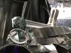
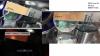
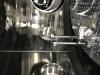
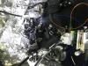
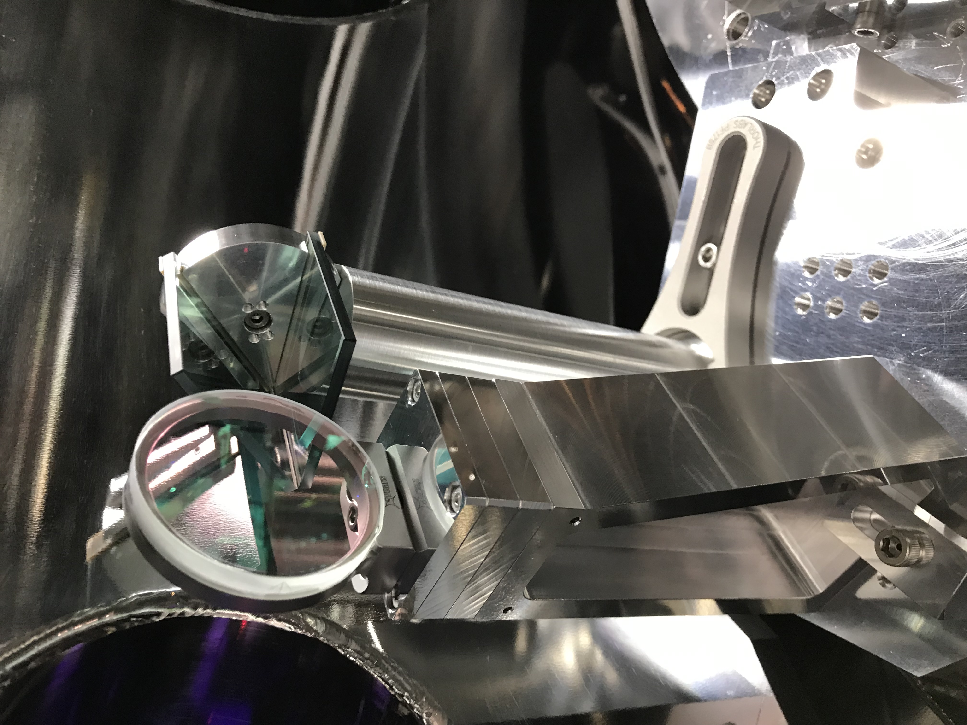
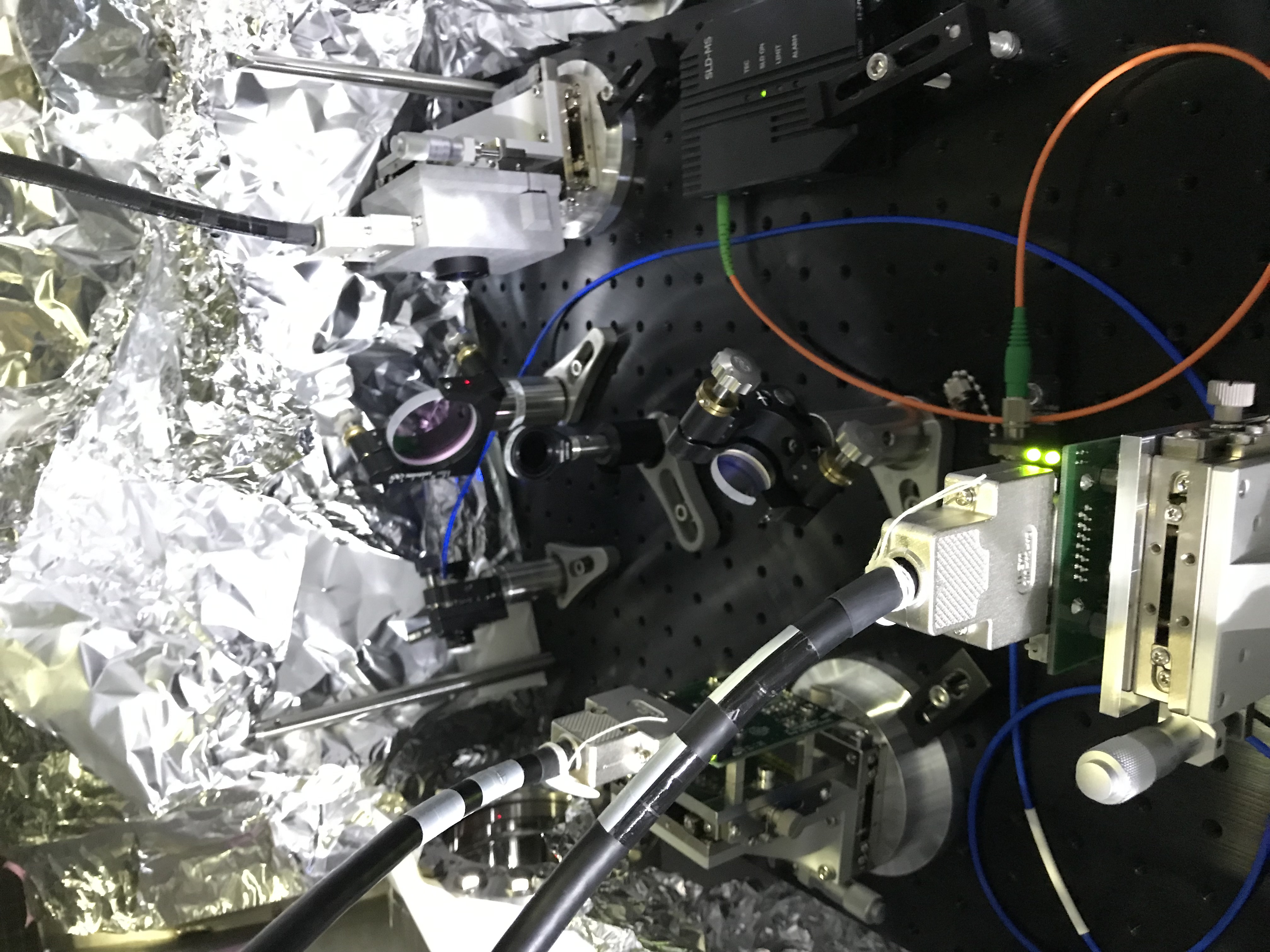
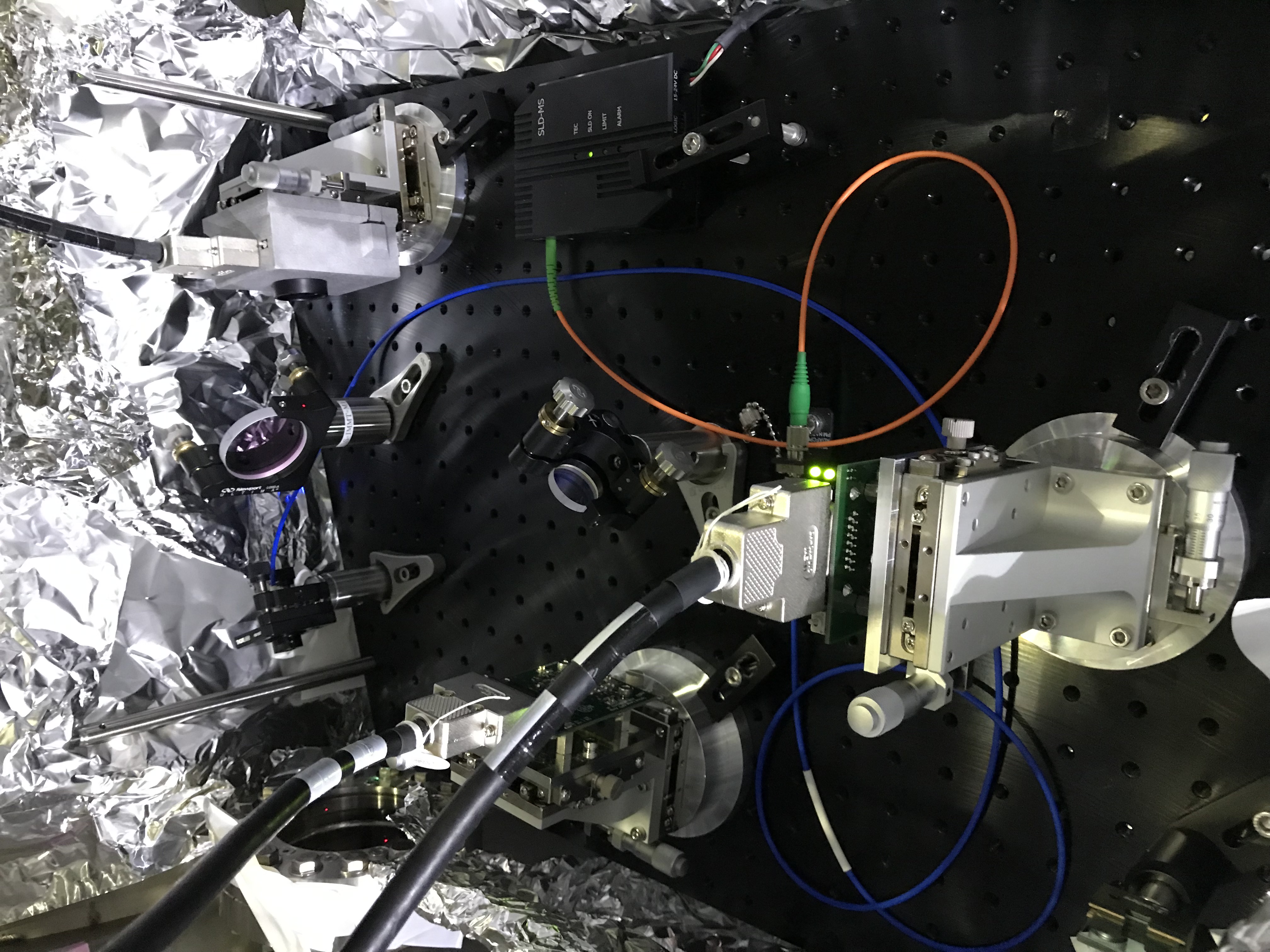
Then, we installed the mirror assembly on the mezzanine board (Fig. 1), and tilted it in yaw so that the reflected beam could pass through as much the center (Fig. 2) as possible of the viewport window for ISS (already installed 19362). We checked whether
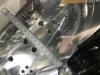
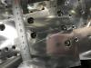
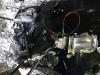
- The IMMT1_TRANS_FORWARD (to be reflected with this mirror HR) would separate properly from the mirror's left edge (+Y direction) -> nominal design is 20 mm (see JGW-T2213831), but today's our setup was ~18mm (Fig. 3); things must be modified depending on the real situation, and so we took slightly different number here. Fig. 4 shows that the left front vertex of the foot structure of the mirror assmbly was about 97 mm away from the edge of the mezzanine board, while the nominal design was 95.26 mm (see JGW-T2213831). Fig. 5 shows that the right front vertex of the foot structure of the mirror assembly was about 75.3 mm away from the edge of the mezzanine board, while the nominal design was 74.591 mm (see again JGW-T2213831).
- The oplev input beam (to IMMT1 AR) could well pass through the left side of mirror assembly (in-situ gap was estimated like 8 mm or so), while the oplev reflection beam from IMMT1 could well enter within the mirror; the mirror coating is AR for the oplev beam wavelength; what we need to avoid is the clipping of the oplev beams against the mirror edge.
- The IMMT1_TRANS_BACKWARD would enter well within the mirror; as of today, the IMMT1_TRANS_BACKWARD beam was imitated with the beam reflected at PRM. Actually we took time to tweak PRM so that the reflection beam from PRM could reach IFO_REFL. After Ushiba-kun did rough maximization of the power at IFO_REFL PD with fine tuning of RPM alignment, we modified the PRM oplev beam paths to make it new reference; otherwise, for some reason, the oplev beam for PRM at RX was severly offset... Yokozawa-san tweaked the oplev TX and somehow recovered the PRM oplev.
Fig.6 summarizes the beam distribution with a sensor card put in front of the IMMT1T-ISS mirror.
Also, the location of the beam dump in the -Y direction of the IMMT1T-ISS mirror was slightly adjusted so that the ghost beams from IMMT1 could be caught as much as possible... hopefully.
Finally, we put two tentative beam dumps in the IMM chamber to catch the reflection beams from the IMMT1T-ISS mirror due to IMMT1_TRANS_FORWARD and IMMT1_TRANS_BACKWARD; indeed in Fig. 7, two beam dumps are shown in the front and back sides, and they are for IMMT1_TRANS_BACKWARD, and IMMT1_TRANS_FORWARD, respectively. For ISS, IMMT1_TRANS_FORWARD should be used.
Post processing
Due to this mirror installation, the beam paths for the IMMT1 oplev and IMMT1T QPDs changed. For IMMT1 oplev, I tweaked te QPD stage to make it centered while Ushiba-kun was monitoring the signals. For IMMT1T QPDs, a steering mirror on the IMMT1 pylon was about to clip the IMMT1_TRANS_FORWARD, so Ushiba-kun asked me to fully adjust the beam path, and now the steering mirror was relocated and tweaked so that IMMT1_TRANS_FORWARD was centered at IMMT1_QPD1 (Fig. 8 is of beforehand, and Fig. 9 is of afterward). I did not care about IMMT1_QPD2 for today.
Some notes
- Luckily, the reflected beam from the IMMT1T-ISS mirror was not severly pitching, while I and Yano-san thought a counermeasure if such sad thing would happen; we had a concern on it if the mezzanine board flatness and the input beam from IFI or some mixture of them would cause pitching. It would have been a nice decision that we took time to fix the height of IFI (and IMMT1) to the nominal height.
- It is hard to access this area in the IMM chamber and to take photos...

