Aso, Ushiba, Yano, Hirose, Tanaka
### Abstract
We continued yesterday's work. We succeeded to send the beam to the center of the IMMT1 TRANS QPDs by tweaking the IP2 mirror with engaging MCI/O DC control by the WFSs. After the alignment, we checked the IR beam path from STM1 to PR2. Now the beam is off-centered about the center of the aperture of the IFI output port but is not clipped. And the beam spot on IMMT1 is lowered at the vertical center of the IMMT1 mirror but it is on the horizontal center of the IMMT1 mirror. We checked the downstream beam path from IMMT2 but we found that IMMT1 and IMMT2 are not in ALIGN state after we went back to Mozumi. So we will check the downstream from IMMT2 tomorrow.
In addition, we have offloaded the DC offset value (K1:IMC-MCREFL_PZT{1,2}_{PIT, YAW}_OFFSET) on the PZTs for DC centering in the MC REFL because it was just the edge of the range.
### What we did
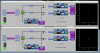
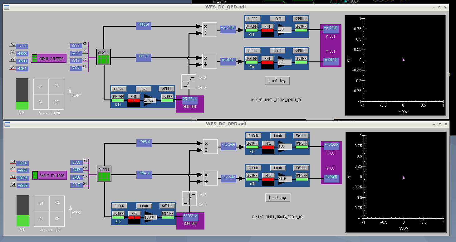
- First, we tweaked the IP2 mirror in the PIT direction to center the beam spot on IMMT1 TRANS QPDs with IP2 PZT offset (K1:IMC-PZT{1, 2}_{PIT, YAW}_OFFSET). Secondly, we tweaked the IP2 mirror in the YAW direction to center the beam spot on IMMT1 TRANS QPDs. While adjusting the IP2 mirror, we took care of the saturation of MCI/O coils. Finally, we succeeded to center the beam spot on IMMT1 TRANS QPDs. (Fig. 1) After finishing the alignment, the IP2 offset value is at the edge of the range.
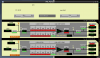
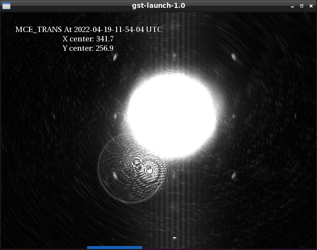
- Then we adjust the beam spot on MCE with MCE OPTICALIGN in the reference to MCE TRANS camera. Since the center of the MCE TRANS camera is roughly at the center of the MCE mirror, the MCE mirror was moved using that as a guide to bring the MCE beam spot to the center of the MCE TRANS camera. (Fig. 2)
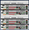
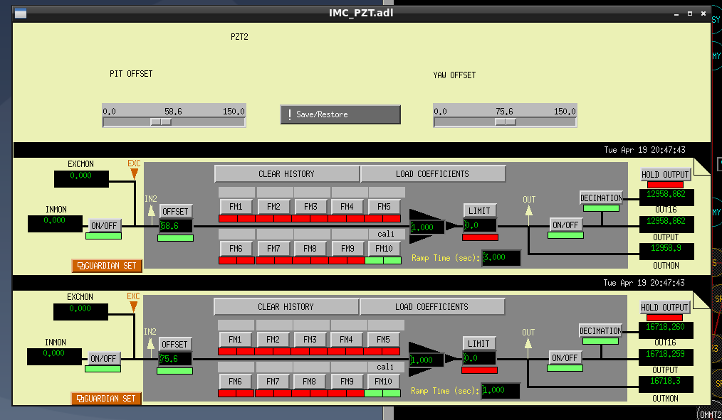
- We entered the mine, and we have offloaded the IP2 PZT offset value. With the output of the DC control held, the mirror of IP2 was moved by hand. Then, when the DC control was turned on, the beam spot position on the IMMT1 TRANSQPD was shifted, so the offset value of IP2 was moved so that the shift was zero. Fig. 3 shows the final IP2 PZT offset values after offloading.
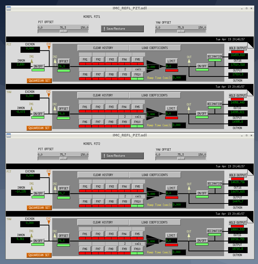
- During the course of this work, we noticed that the PZT offsets for the WFS centering loop (K1:IMC-MCREFL_PZT{1, 2}_{PIT, YAW}_OFFSET) were also coming to the end of the range, so we offloaded these as well. Fig. 4 shows the final MCREFL PZT offset values after offloading.
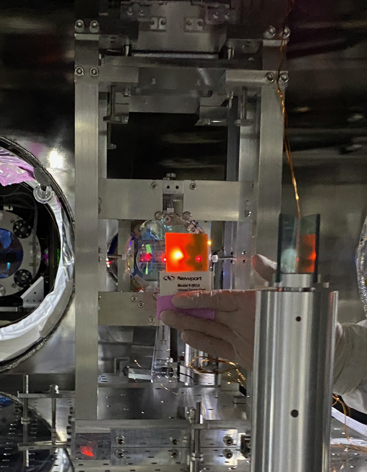
- After offloading the IP2 PZT, we checked where the beam downstream from the IMC was going. First, the beam at the exit of the IFI was slightly offset from the center of the exit aperture to the +Y side. It did not seem to be clipped.
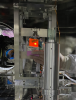
- Fig. 5 is a photo taken from below with the camera aligned with the horizontal center; Fig. 6 is a photo taken from the side with the camera aligned with the vertical center. According to these photo the beam on the IMMT1 appears to be almost at the center in the both horizontal and vertical direction.
- We checked the downstream beam path from IMMT2 but we found that IMMT1 and IMMT2 are not in ALIGN state after we went back to Mozumi. So we will check the downstream from IMMT2 tomorrow.

