Aso, Hirose, Ushiba, Tanaka
### Abstract
We tried to align the output axis with IMC and IP1,2 mirrors, We gave up aligning the output axis manually. So we implement the control loops of MCI/O mirrors with WFS1,2 to follow the MCI/O when we move IP1,2 mirrors. Now, the control loops work well and the throughput of IMC is maximum (input: ~2.6 W, output: ~2.5 W, throughput: ~96%). But the output axis is not aligned yet. Tomorrow, we continue this alignment work.
### What we did
- First, we tried to align the output axis of IMC with MC mirrors and IP1, 2. However we found that it is too difficult to align it with the method because when one mirror is moved, the amount of transmitted light falls, so the other mirrors are used to supplement, but then the range is full somewhere, or the amount of transmitted light is not restored. In other words, it is impossible to move all the mirrors with care for all the degrees of freedom.
- Therefore, we decided to add a control to return the WFS signal to MCI and MCO so that the cavity axis follows the incident light axis. This allows us to move the beam spot on the transmitted QPD of IMMT1 by simply moving the incident optical axis while maintaining the transmitted power.
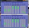
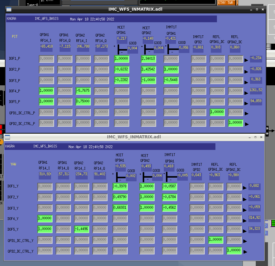
- First, MCI and MCO were moved to PIT/YAW to measure their responses in WFS1, 2 @15 ~ 20 Hz. These results are /users/Commissiong/data/IMC/TF_sup/20220418/. Based on these results, a sensing matrix was created. (Fig. 1)
The relationship between each DOF and the mirror is summarized below.- DOF4 P/Y -> MCI -> P/Y
- DOF5 P/Y -> MCO P/Y
- For each mirror, the transfer function from the actuator to the sensor was measured at 0.3 Hz. These results are /users/Commissiong/IMC/PLANT/20220418. Based on the results, a first-order integrator was added so that the UGF would be about 0.3 Hz.
- When control was applied only in the YAW direction, oscillation occurred at 2 Hz, which is the resonance of YAW, so a notch filter was added at 2 Hz.
- When the control was turned on, the amount of throughput was maximized (input: ~2.6W, output: ~2.5 W, throughput:2.5/2.6 = ~96%)and the image of the beam was lost from the reflected light camera. (Fig. 2)
- IP2 was then moved to confirm that the beam spot on the IMMT1 transmission QPD moved. At this time, we took care not to saturate the output of the actuator coils of each mirror as the MCI and MCO were followed by the WFS as IP2 was moved. If they were about to be saturated, we offloaded them by using pico motors so that the value (K1:VIS-MC{I, O}_TM_SUMOUT_{P, Y}_OUTPUT) would be zero.
- During the work, we noticed that the offset values that must be applied to IP1 and IP2 have changed considerably (~+/- 20 V) between the time when the MC chamber was opened and this time.
- Because IMC was down during the work due to the earthquake, we decided to stop today's work and continue it tomorrow. Finally, all offsets on the MC coils were offloaded by the picomotor. At this time, the angle of the MC mirror was restored to the value of the oplev when the control was applied.
