During the work of beam check (klog20401), I found BF horizontal LVDTs were not working.
So, they should be investigated.
AA chassis and the Dsub cable between AA chassis and LVDT Driver chassis seem to be alive.
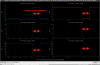
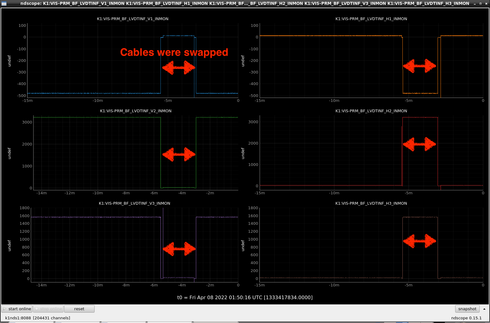
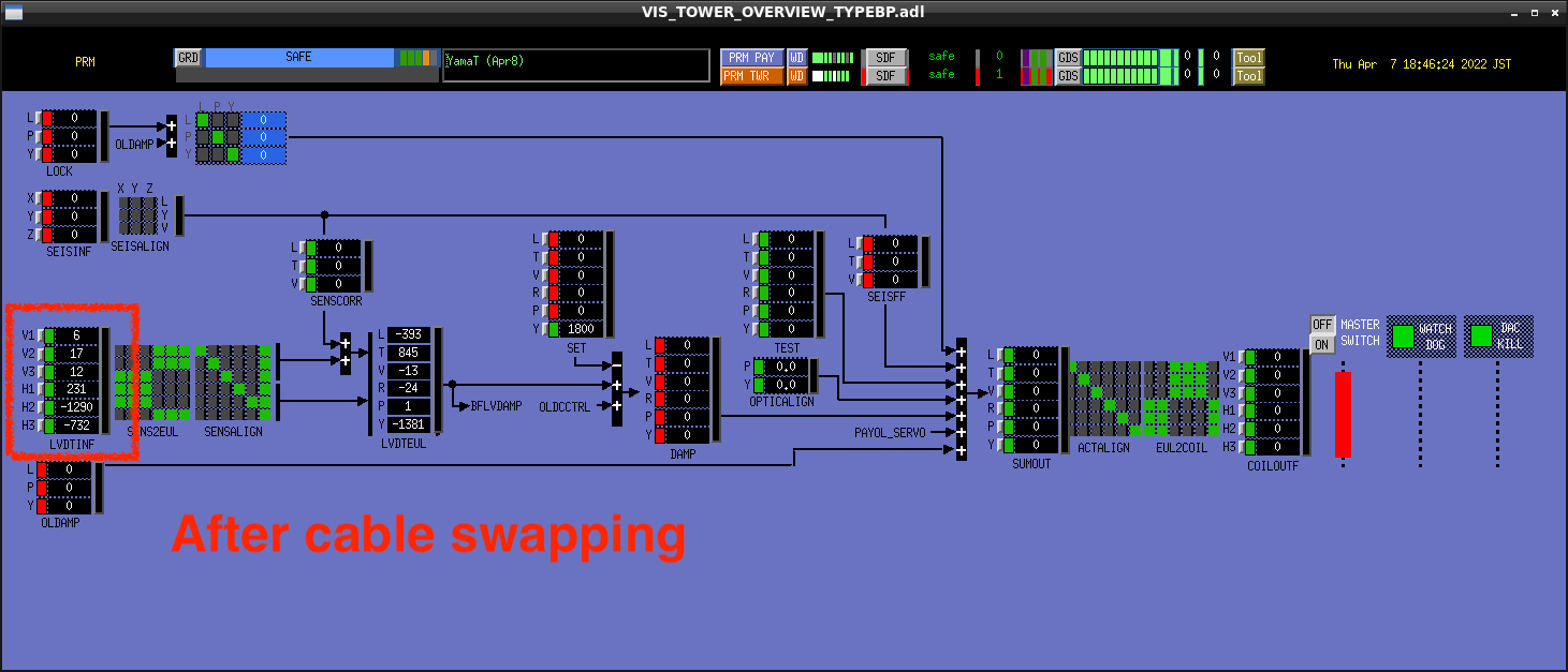
I swapped the cables of BF-V and BF-H at the input port of the AA chassis.
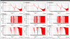
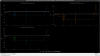
Then BF-V channels showed ADC-noise like signals and BF-H channels showed the signals which had been seen on BF-V channels before cable swapping as shown in Fig.1, Fig.2 and Fig.3.
And also, I swapped the cables at the sensor output port of the LVDT Driver chassis.
In this case, behavior of BF-H and BF-V channels were same.
With Takahashi-san and Hirata-san.
Summary: We replaced the LVDT card for the BF Horizontal LVDTs. Now they seem to be giving appropriate signals, but we still need to determine the new calibration factors.
We successfully measured the values of the LVDT coil resistances at the cable coming from the vacuum chamber. This suggested the problem was the LVDT card itself, therefore, we proceeded to change it.
We followed this procedure:
- In the broken board, we measured the resistance values that determine the input and output gains. See the table below and the document JGW-T2012128-v2.
- We adjusted the resistances in the new board to have almost the same values (see table below).
- We installed the LVDT driver in the rack and saw that the readout looked functional.
- Using an oscilloscope, at each channel, we adjusted the phase such that the output was maximum.
The next step is to measure transfer functions of the individual LVDTs, compare with previous measurements, and then calculate the new calibration factor. However, currently it's not possible to take measurements because of a problem in the digital system. We'll do it once the problem is solved.
| Resistance | Broken LVDT card value (kOhm) | New LVDT card value (kOhm) |
| D1 | 4.643 | 4.636 |
| D0 | 5.092 | 5.082 |
| D3 | 5.004 | 4.988 |
| D4 (D2) | 5.422 | 5.449 |
| G0 | 89.7 Ohm | 89.3 Ohm |
| G1 | 99.5 Ohm | 99.4 Ohm |
| G2 | 88.1 Ohm | 88.3 Ohm |
| G3 | 91.4 Ohm | 91.2 Ohm |
With Hirata-san.
Summary: we calculated the new calibration factors of the BF horizontal LVDTs based on previous measurements of transfer functions.
We followed this procedure:
- We set the calibration factors of the three horizontal LVDTs to -1 (the original factors were negative).
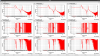
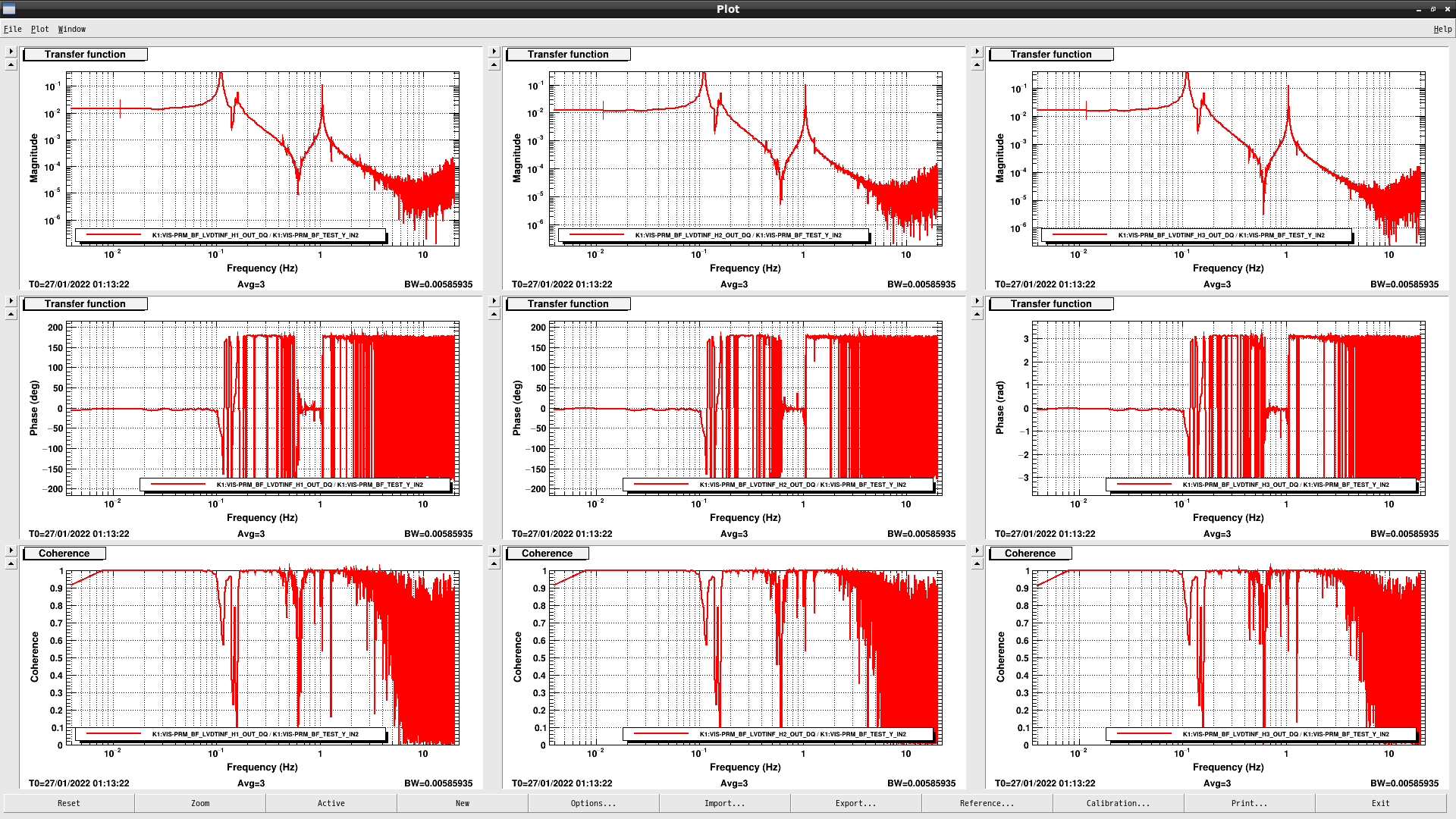
- We measured the transfer functions from BF yaw actuation to BF yaw displacement, including those from yaw actuation to LVDTs H1, H2 and H3. These measurements are in /kagra/Dropbox/Subsystems/VIS/TypeBpData/PRM/TF/Measurements/20220413/.
- To calculate the new calibration factors, we compared the DC amplitues of the new measurements with the measurements referred to in klog 19602, which are in /users/VISsvn/TypeBp/PRM/TF/Measurements/20220127/.
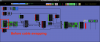
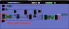
From left to right, the table below shows the DC amplitudes of the transfer functions measured with the calibrated LVDTs (on January 27th), without calibration (-1) and with the new calibration factor. The calibration factors were calculated as the ratio of the values in the first column divided by the values in the second column. The third colum show the new calibration factors, which have been written in the medm screen and accepted in the SDF already. As can be seen, the values in the third column are close enough to those in the first one.
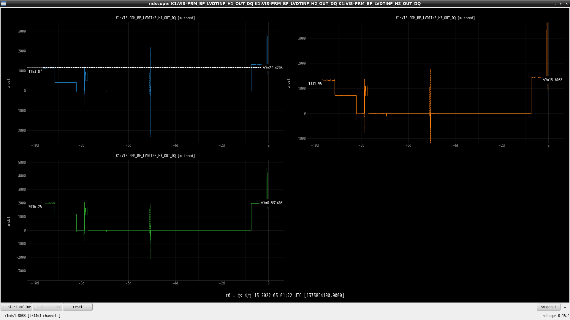
The screenshots show the SDF screen, the old and new transfer functions and Ndscope plots showing the difference in postions measured by the LVDTs before and after the replacement of the LVDT card. The differences are very small, 27, 15 and 0.5 um for H1, H2 and H3 respectively. The details of the plots cannot be appreciated from the screenshots, so you might just want to accept my word. Notice that for about 10 days the system was either off or the BF was set in a different position.
| Measurement | Calibrated model (um/cnt at 11 mHz) | Without calibration (cnt/cnt at 11 mHz) | With new calibration factor (um/cnt) | New calibration factor (um/cnt) |
| Y → H1 | 0.01429 | 0.03321 | 0.01433 | -0.4302 |
| Y → H2 | 0.01218 | 0.03263 | 0.01211 | -0.3732 |
| Y → H3 | 0.01586 | 0.03326 | 0.01589 | -0.4769 |
