[Tamaki, Tanaka, Ushiba]
Abstract:
We finely aligned MC mirrors to see TEM00 flash.
Then, we aligned the IMMT1, IMMT2, and PRM, and checked the beam position on POM1 and POM2.
The spot positions seems well, so we can proceed the vacuum closing process.
Detail:
First, we moved MCI and MCE so that OpLev signals are zeros, which is the good alignment for IMC before evacuation.
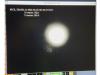
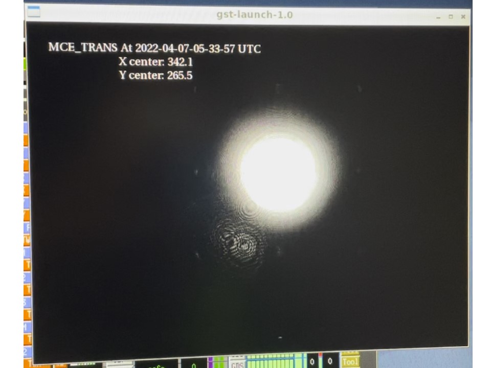
Then, MCO was aligned to maximize the transmitted TEM00 power on MCE trans PD.
After the above alignment, beam position in the MCE trans caamera image seemed to move to the top right, which means beam position on MCE moved.
So, we moved MCE and MCO to recover the beam position on the image while keeping the TEM00 flash.
Figure 1 shows the MCE trans camera image after the tuning.
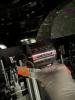
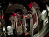
After the alignment, we set beam damp between MCO and MCI not to flash the IMC and removed HWP in the PSL room to check the beam postion on POM1 and POM2.
Figure 2 and 3 show the beam position on POM1 and POM2, respectively.
It is hard to identify from the photo, the beam on POM1 andd POM2 seemed to hit almost center of the mirror.
After this work, we centered the OpLev of MCO and MCE, and offload all actuators of MC suspensions.
So, IMC alignment is almost good without any offset from the coils now.
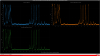
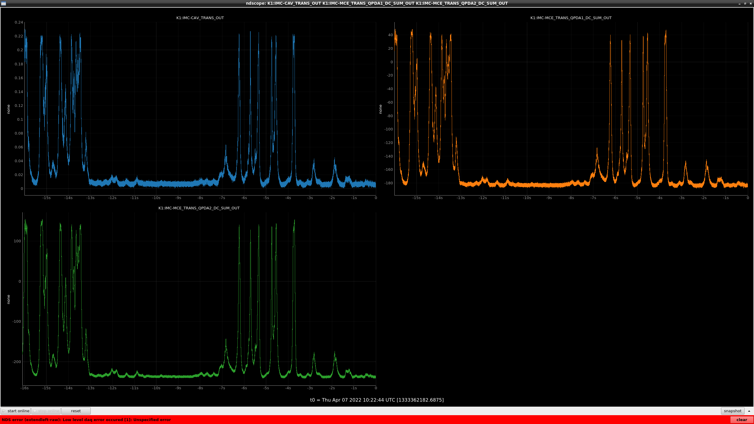
the MCE trans QPD signals were also checked but it is difficult to confirm the beam position by using MCE trans QPDs because the MCE cannot be locked in the atmospheric pressure,
So, I just checked the MCE trans QPDA1 and QPDA2 SUM if the transmitted beam are on the QPDs (fig4).
Both QPD sums increase when the IMC trans power is increasing, so the alignment seems fine.