Reports 1-1 of 1 Clear search Modify search
DGS (General)
satoru.ikeda - 15:42 Tuesday 15 March 2022 (20084) Print this report
Installation of LAN cables for Piconet(HWP,FunctionGenerator,Picomotor), DGS(WS)

[Ikeda, Hayakawa-san, Takahashi-san, Yoshimura-san, Omae-san ]

LAN cables were installed for use in the following

HWP(Pico) and WS(DGS) of PSL (Fig. 4,5,6)
HWP (Pico) and function generator (Pico) at IMC
=> Installed up to the cable rack in the clean booth on the PSL side of IMC.
 Work will be done in the next PLS and clean booth.

HWP (Pico) and Picomotor (Pico) at OMC(Fig. 1,2)
=> Used to use Piconet near AS table.

On another matter, LAN cables were routed halfway up the PSL room. (Fig. 3)
This cable length was too short to reroute.
It would be easier to install other cables if they were wired a little cleaner.
 

Images attached to this report
Non-image files attached to this report
Comments to this report:
satoru.ikeda - 14:10 Thursday 17 March 2022 (20119) Print this report

[Ikeda, Miyakawa-san, Nakagaki-san, Yoshimura-san, Takahashi-san]

LAN cables from DGS and Pico network were routed to the PSL room.

Connection to network SW behind PSL room (Fig.1)
 Port09: Pico PSL room (dedicated line for HWP PC PoE)
 Port17: DGS PSL room (k1ctr12, Wi-Fi router, Moku)

The LAN cable of network SW (k1ctr12, Wi-Fi router, Moku) was replaced with a new DGS LAN cable.

The original DGS network cable was connected from Wi-Fi near IOO. (Fig.2)
 This cable was wired above the floor and was removed. (Fig.3)
 We plan to remove the LAN cable from the PSL room next time.

The LAN cable was connected to the PC for HWP and placed on the mesh shelf. (Fig.4)
  We have not yet connected this PC to HWP.

Images attached to this comment
Non-image files attached to this comment
satoru.ikeda - 13:41 Friday 18 March 2022 (20153) Print this report

[Ikeda, Nakagaki-san, K.Tanaka-san]

The PC for controlling the HWP rotator in the PSL room was changed from WS (k1ctr12) to dedicated (k1hwp0).

Work details :
1. Before changing to the new PC, the operation of the HWP was checked. (Fig.5, 6)
 First, we checked to see if the HWP worked before entering the PSL room.
 This did not work.

2. We entered the PSL room and checked if the HWP worked.
 This did not work.

3. Disconnected the USB cable and operated the HWP at the same time when it was plugged in.
 After that, when I got it working, it started working.

4. I plugged the USB into a new PC. (The spell of 3 is not necessary for the new PC.) (Fig.1, 2)
 The operation was checked and the work was completed.

5. The LAN cable previously used was removed. (Fig.4)
 We checked the quality of the cable as a test, and found that it had no problem.

6. Finally, we checked the EPCIS channel during the work.(Fig.7)
  After the PSL room lighting was turned on, K1:LAS-POW_PSL2_OUTPUT showed a converging movement, but no other problems were noted.

Regarding the connection :
 k1hwp0 (10.68.160.170) is connected to the Pico network and needs access from k1script1.


Images attached to this comment
Non-image files attached to this comment
satoru.ikeda - 14:23 Thursday 24 March 2022 (20220) Print this report

[Ikeda, Nakagaki-san]

Continued from K-Log#20084

LAN cables were installed for use with Function Generator and IMC REFL and REFL HWP.
The cables were routed on top of the cable rack.

Two cables for the Function Generator were routed to the ALS0 rack. (Fig.1)
 => After moving the script from k1script(python2) to k1script1(python3), we need to replace the network from DGS to PicoNet.

LAN cables used in IMC REFL and REFL HWPs were wired with LAN cables to IMC REFL. (Fig.2)
 => Currently not connected to PC. We plan to connect to PC next time.

The USB-LAN cable that was installed for the purpose of connecting to the WS that was used to run the HWP of IMC REFL/REFL in the past, the connector of the cable was moved near REFL in order to remove it in the future. (Fig.3)
 This old USB-LAN cable will be removed after connecting to the PC.

Images attached to this comment
Non-image files attached to this comment
satoru.ikeda - 17:45 Friday 25 March 2022 (20237) Print this report

[Ikeda, K.Tanaka-san]

This is a continuation of K-Log#20153.

We changed the HWP rotator in the PSL room to one with an encoder.

Procedure
1. The rotator with encoder was connected to the new PC to check its operation.

 HWP Calibration Paramaters were changed to the following values
  K1:SYS-HWP_PSL_CT_PER_DEG_{P,N} = {1.0, 1.0}
  Before change: Fig. 1
  After the change:Fig.2

 => It did not work at first because I forgot that k1ctr12's Debian had VersionUp.
  But this was fixed and confirmed to work.

2. I removed the old rotator and replaced it with a new one.
 However, the old cable was out of reach and we could not remove everything.Fig.3
 The old motor driver was taken back to Mozumi.

3. We checked the operation with the new script.
 We confirmed that it works properly.
 For the final setting, the EPICS channel (K1:SYS-HWP_PSL_STEP_TOTAL_DEG) was rewritten with the minimum value of the output as 0deg.

4. Finally, the new PC was fixed with cable ties. Fig.4

All the work to replace the HWP in the PSL room is now complete.
 

Images attached to this comment
Non-image files attached to this comment
satoru.ikeda - 14:47 Wednesday 30 March 2022 (20299) Print this report

K1:SYS-HWP_PLS_STEP_TOTAL_DEG
=> PSL's HWP was replaced with encoder and TOTAL_DEG became a meaningful value, so SDF was changed to MON.
 

Images attached to this comment
Non-image files attached to this comment
satoru.ikeda - 15:55 Thursday 31 March 2022 (20317) Print this report

Moved PLL X,Y script from k1script to k1script1.
The following changes were made accordingly
k1script is set to STOP state by supervisorctl.
We will see how it goes with k1script1 for a while.

The directory :
 /opt/rtcds/userapps/release/cds/common/scripts/epics-motor-control/keysights/

File :
 freqmonitor_XPLL.py
 freqmonitor_YPLL.py
  => Unify to freqmonitor_PLL.py
  freqmonitor_PLL.py [PLL_X or PLL_Y].

 pcas_xpll.py
 pcas_ypll.py
  => Unified to pcas_pll.py
  pcas_pll.py [PLL_X or PLL_Y]

Operating Environment:
 conda activate freqpll
  The following environment is installed in this environment.
  [Procedure].
  $ conda create -n freqpll python=3.8
  $ conda activate freqpll
  $ conda install pyvisa
  $ conda install pyvisa-py

Supervisorctl Related:
 /etc/supervisor/conf.d/k1als.conf
 $ sudo supervisorctl reread

Non-image files attached to this comment
satoru.ikeda - 15:20 Friday 01 April 2022 (20334) Print this report

I checked if the parameters were changed by the operation from k1script1 changed in K-Log#20317.
This was working properly.

Next, we investigated how to change the IP address of Function Generator.

In the process of investigation, we decided to adjust the schedule because changing the IP address may cause a reboot.
We will also refer to the other K-Log#16155 for other operating procedures.

K-Log#16155 excerpt
> Note:
> Please disconnect the LAN cables if you want to change settings by If reconnect the LAN cables, the remote mode will be recovered automatically.
 

Non-image files attached to this comment
satoru.ikeda - 13:42 Friday 08 April 2022 (20415) Print this report

IP address of PLL FunctionGenerator in Green-X,Y moved to Pico network.

PROCEDURE:
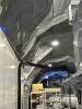
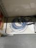
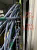
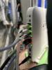
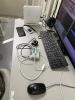
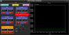
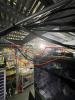
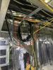
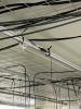
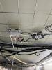
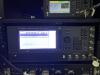
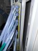
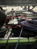
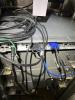
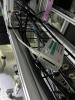
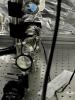
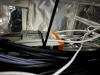
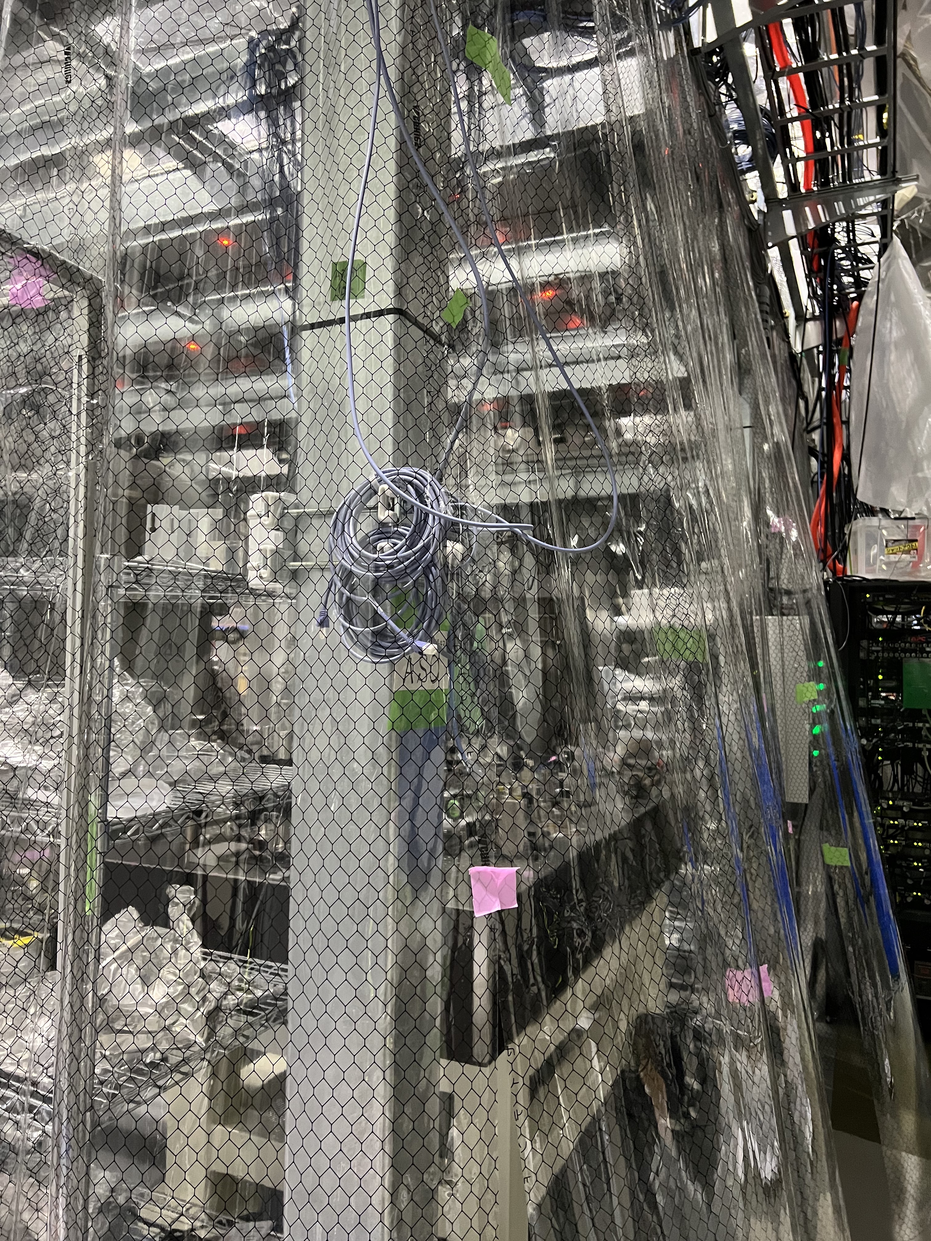
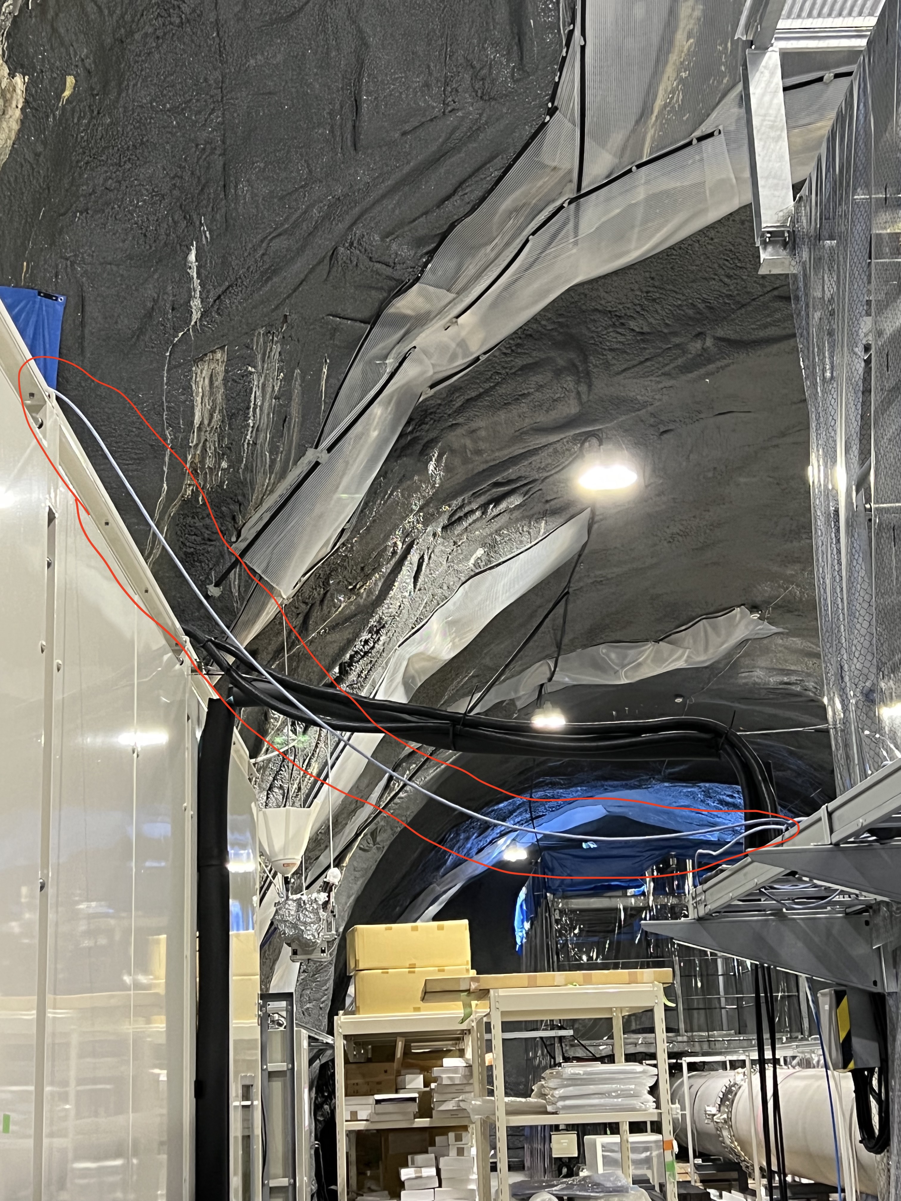
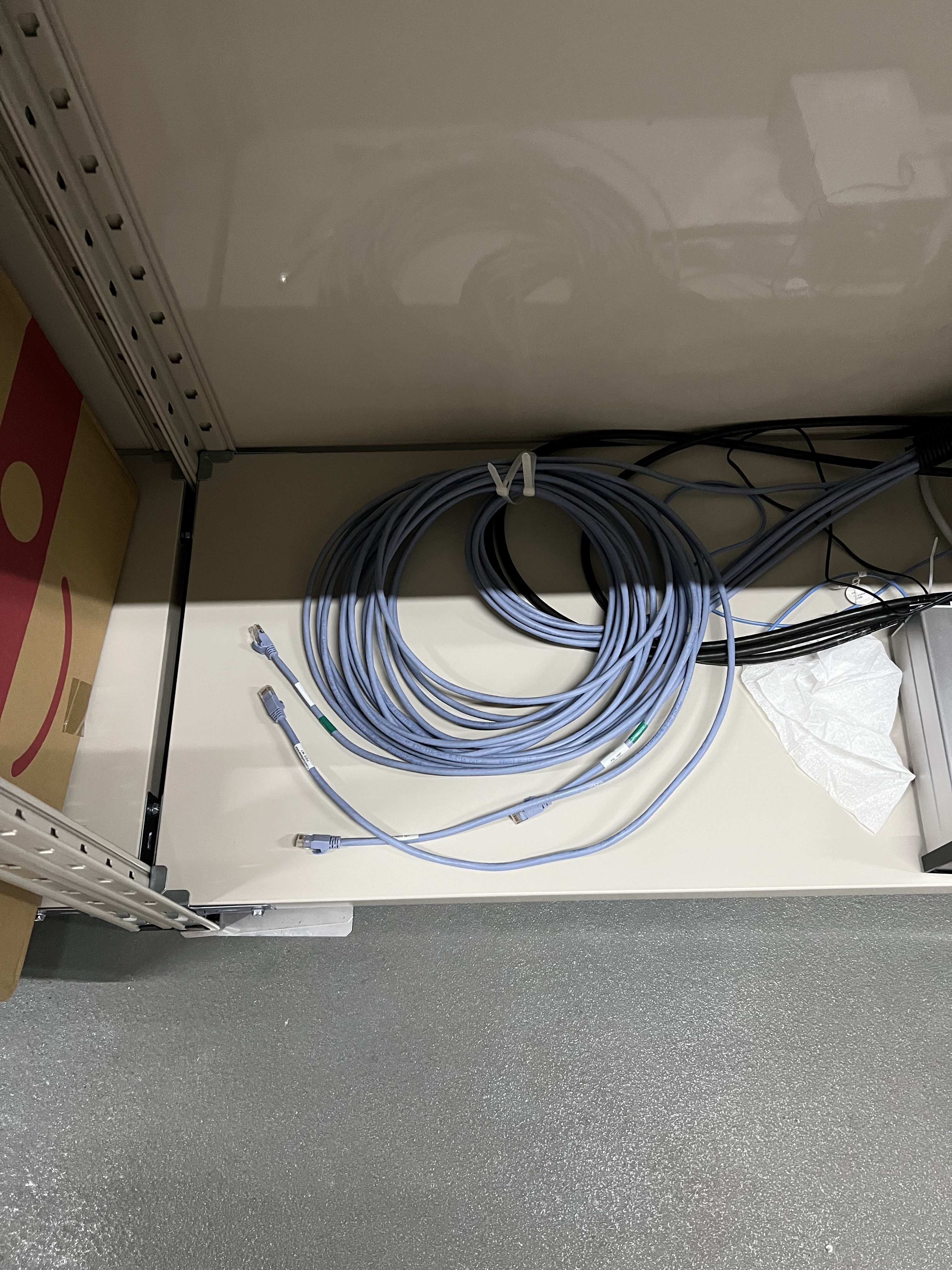
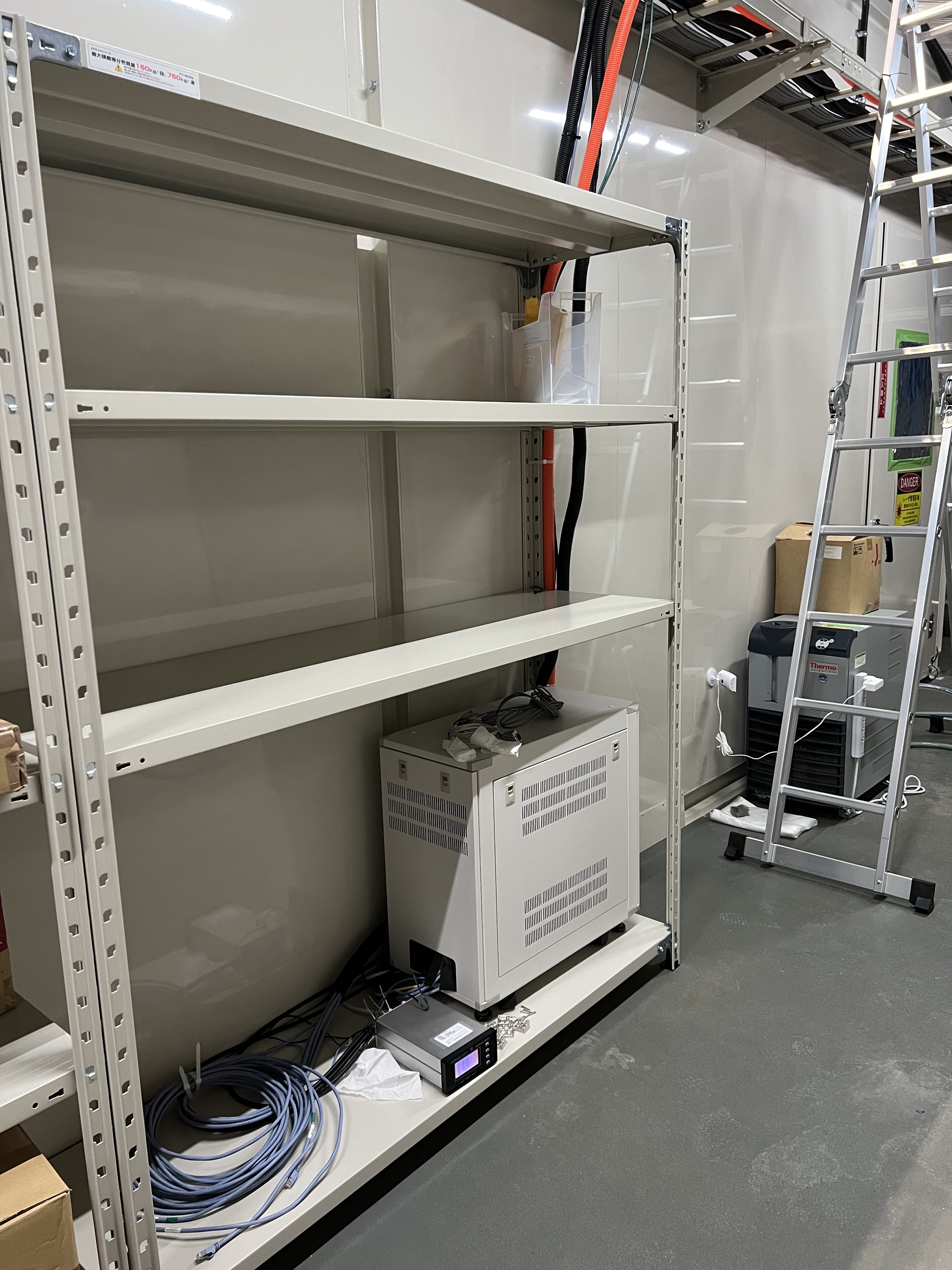
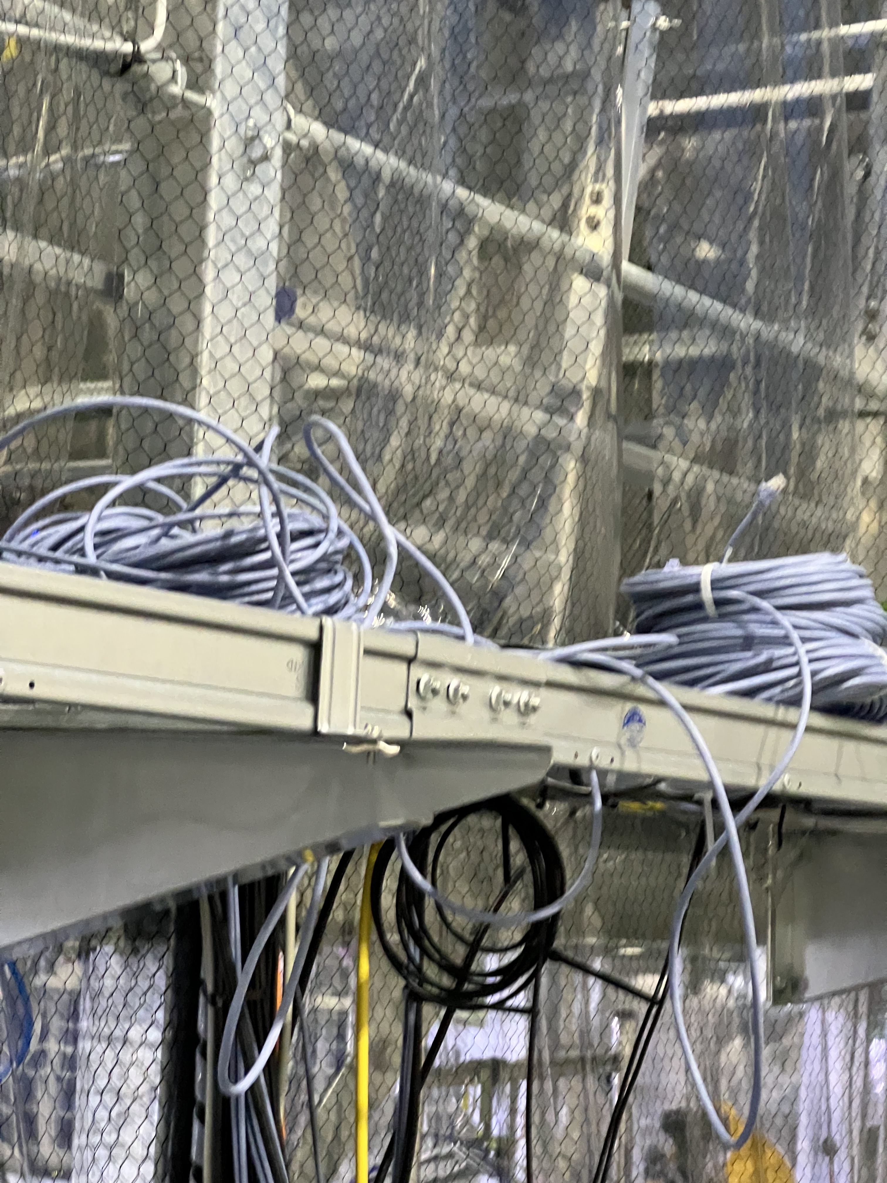
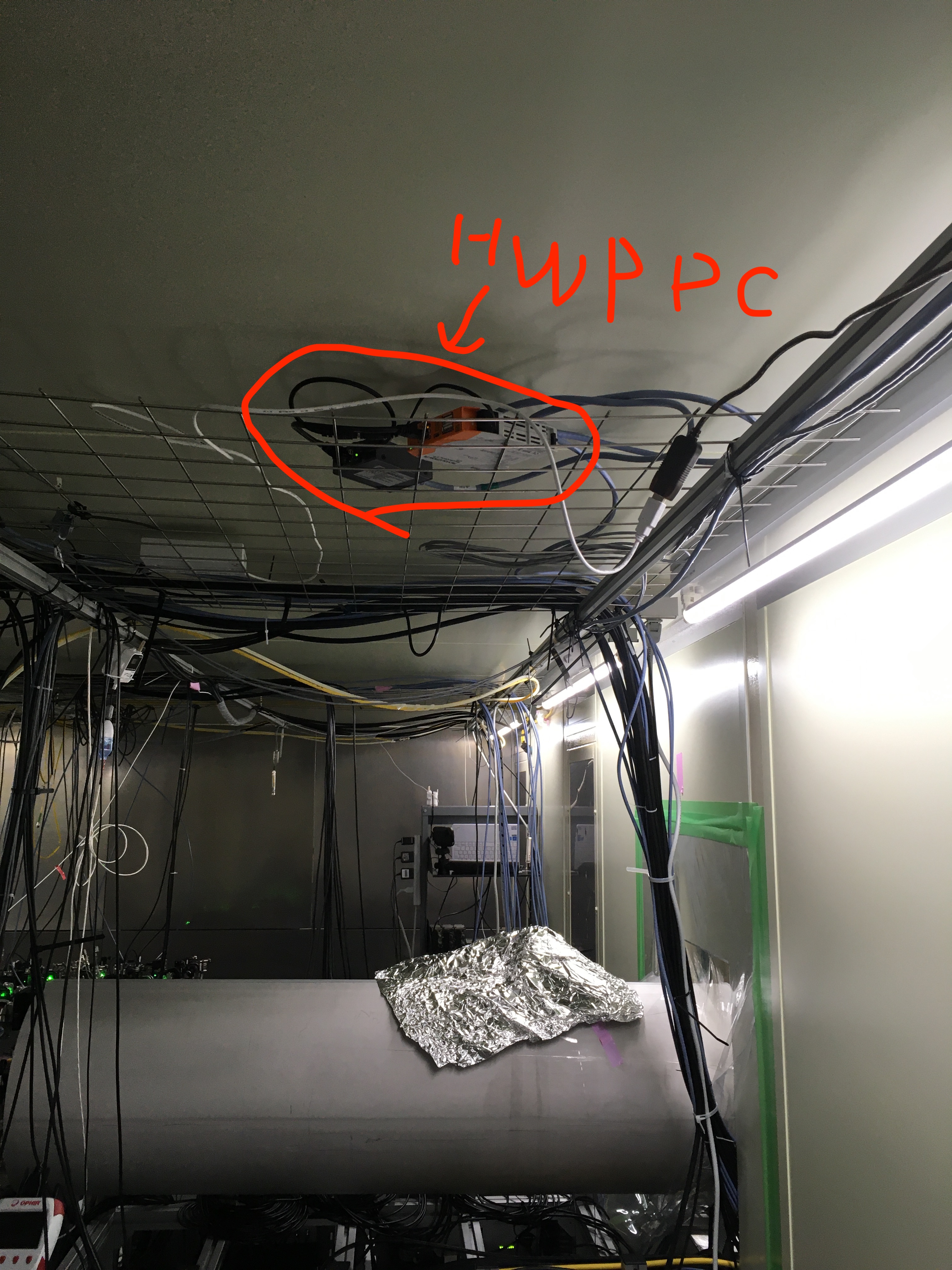
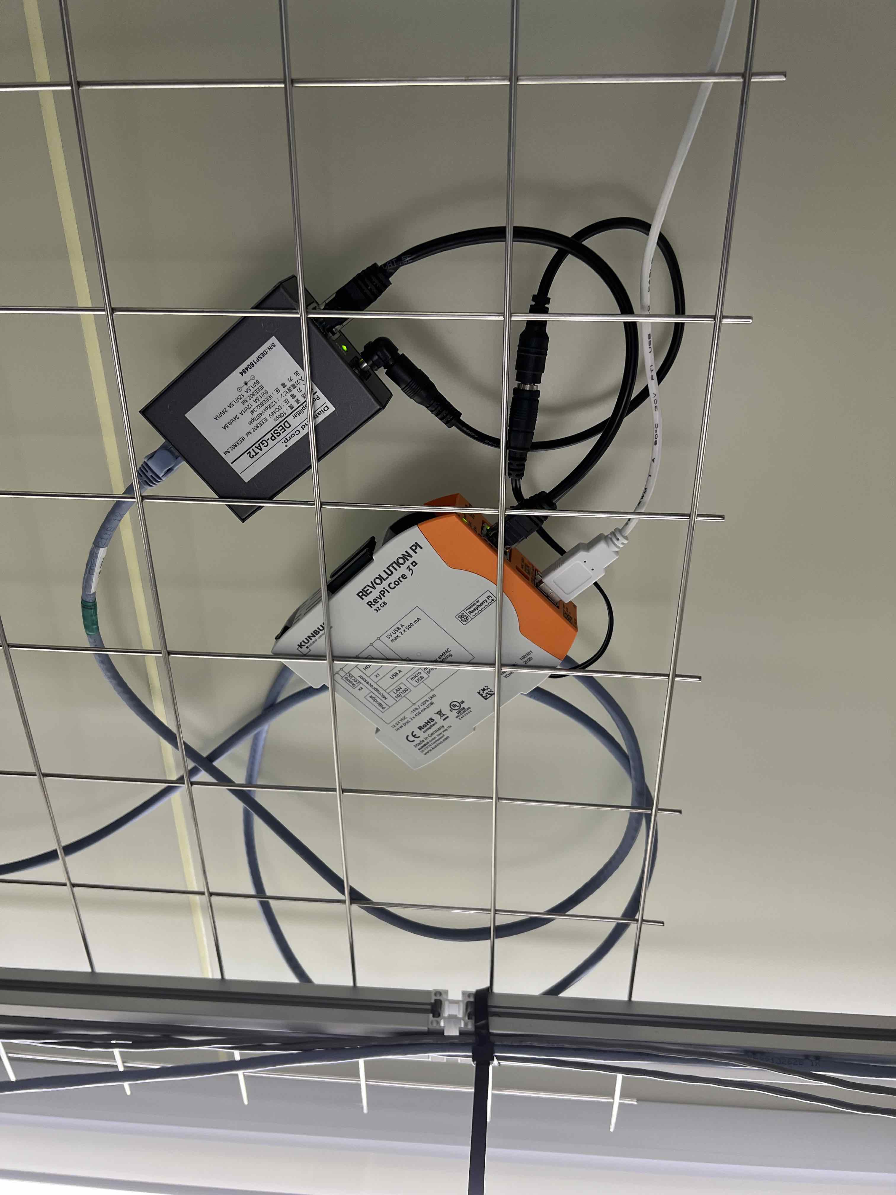
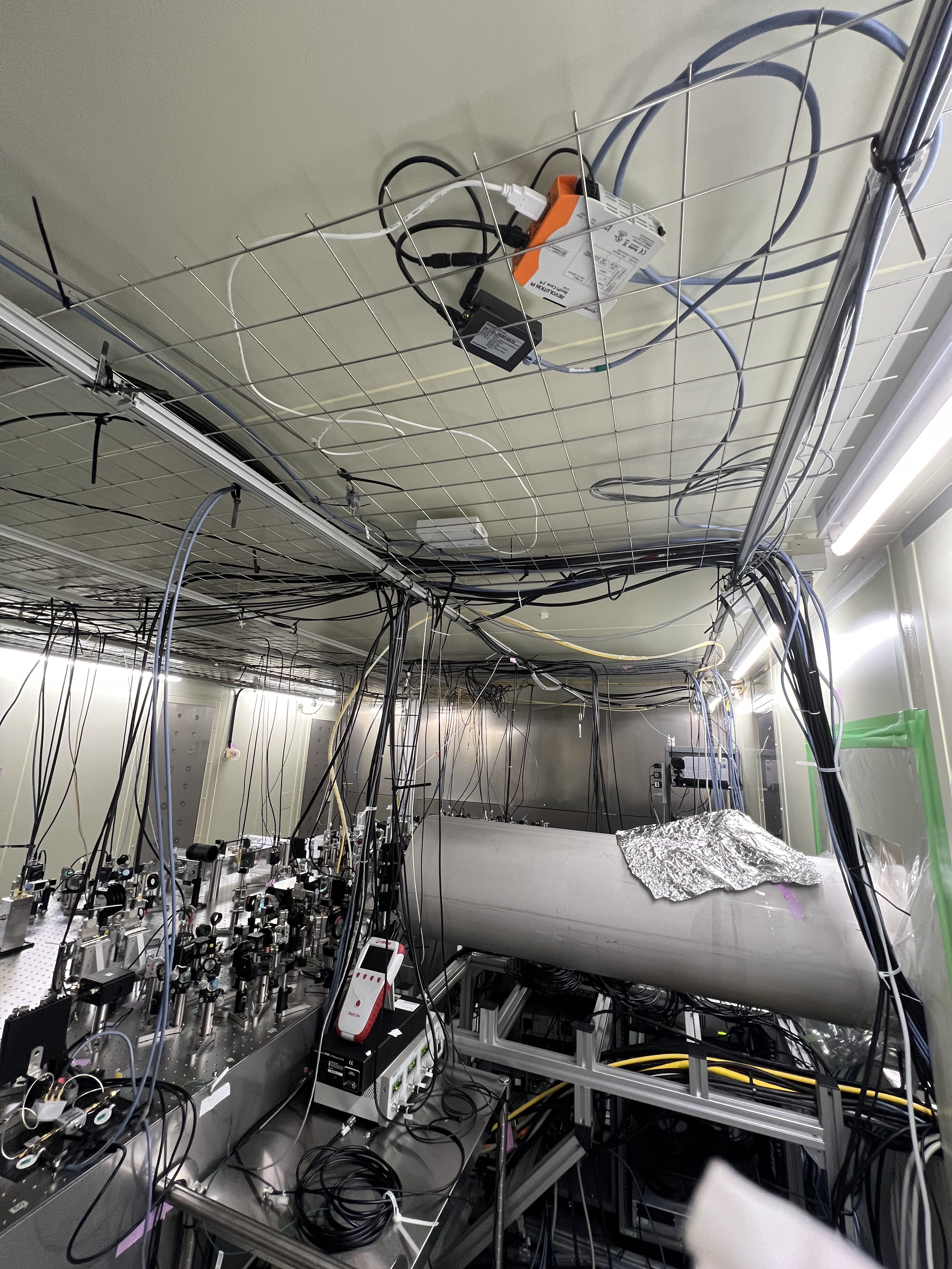
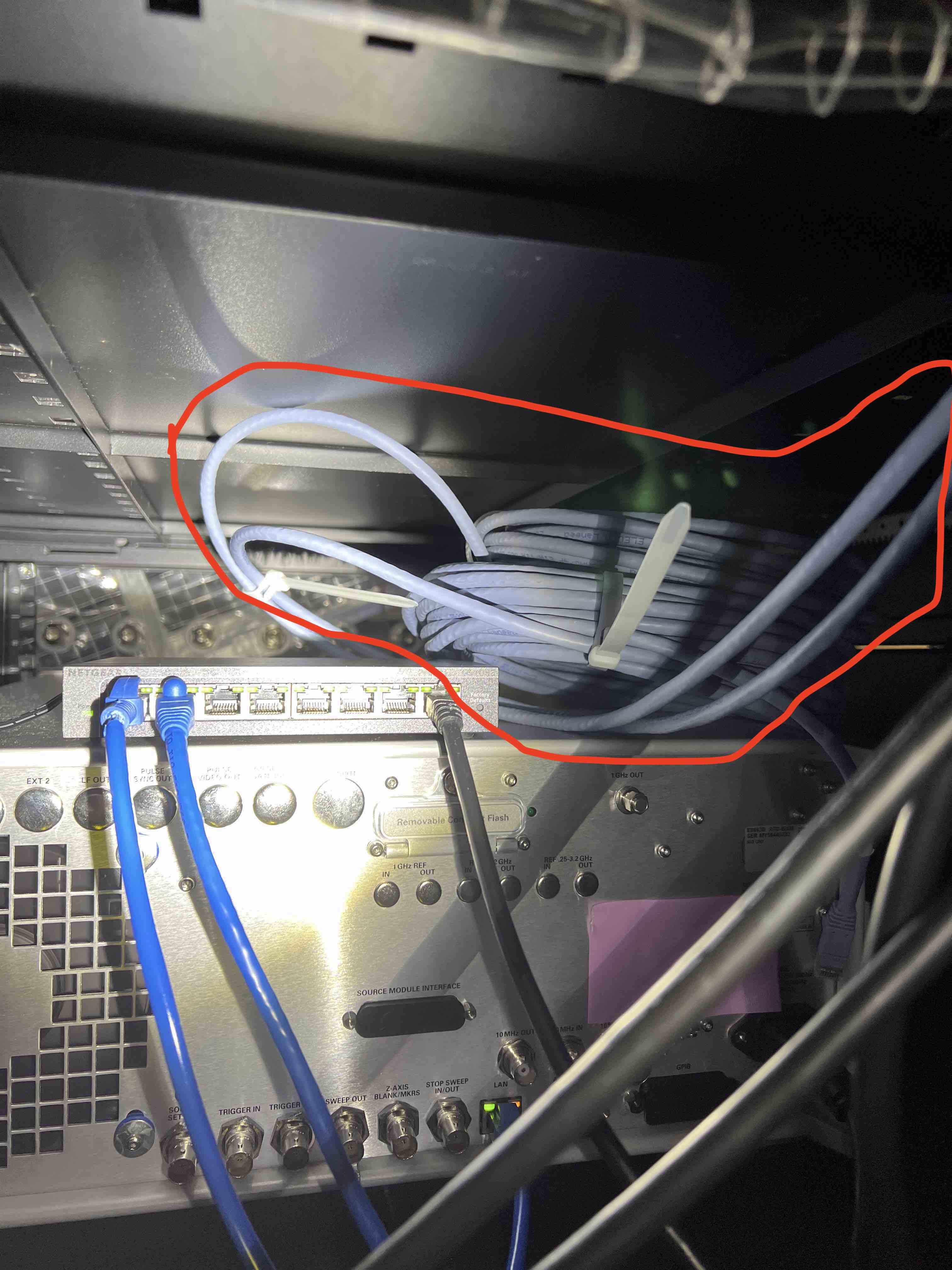
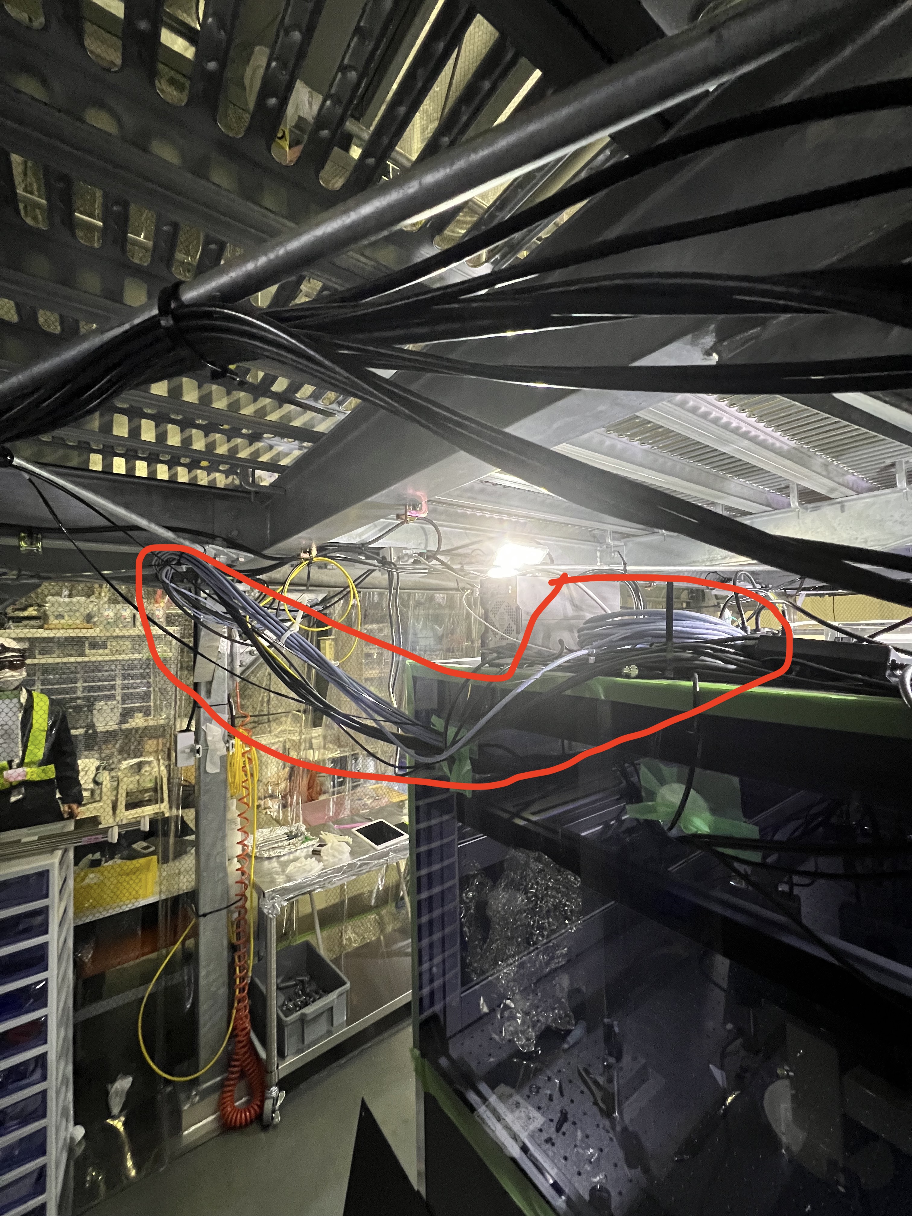
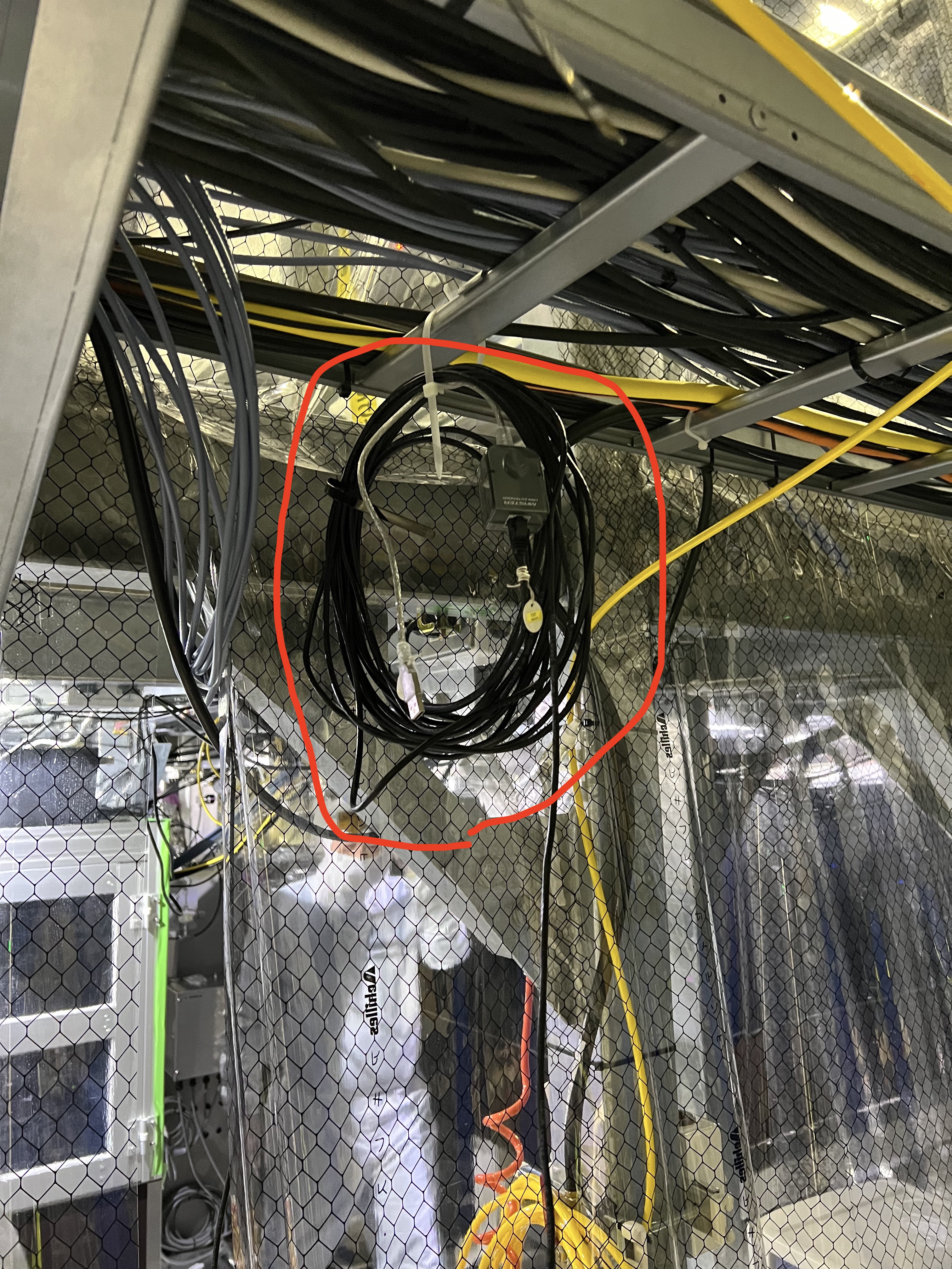
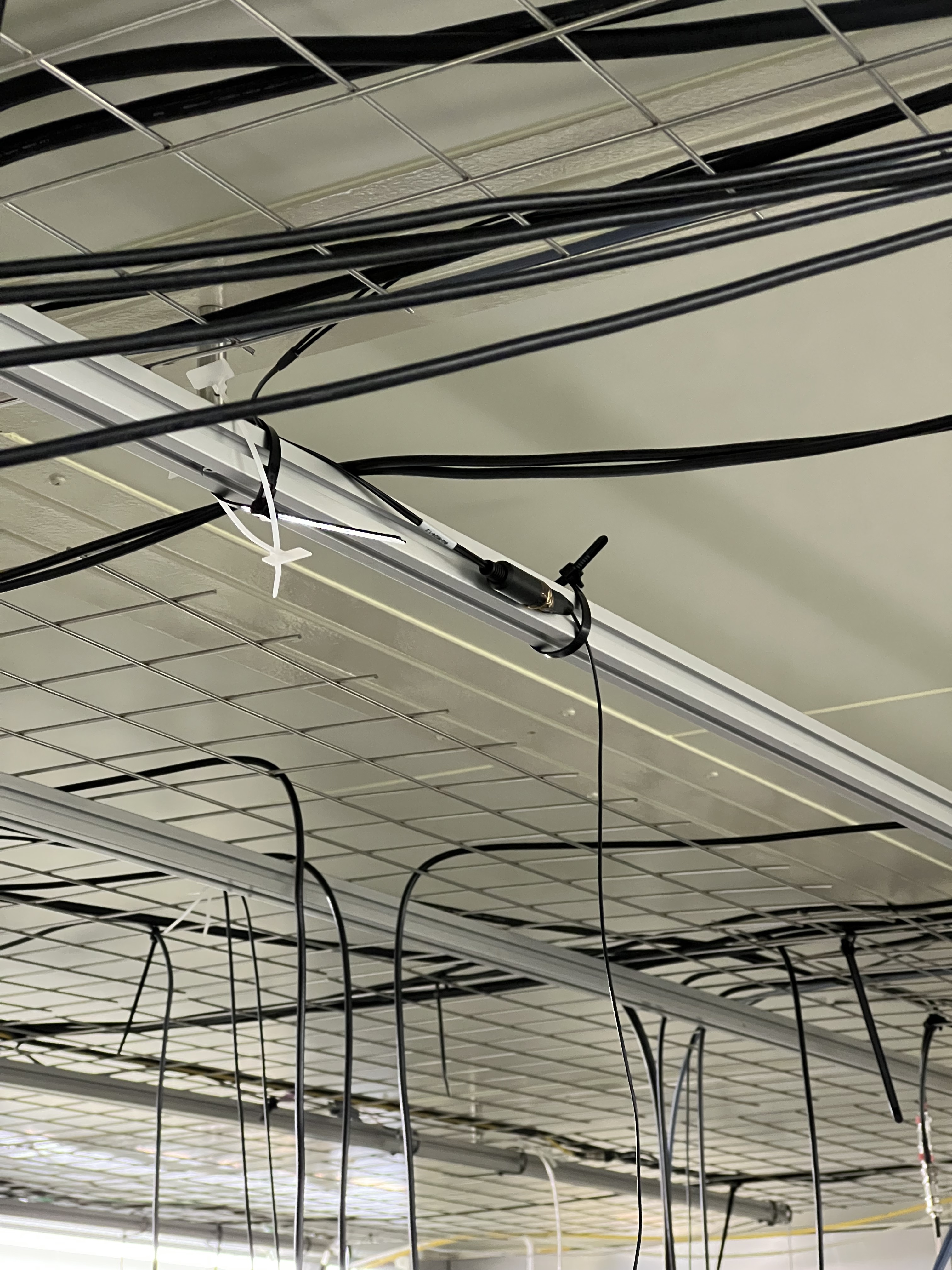
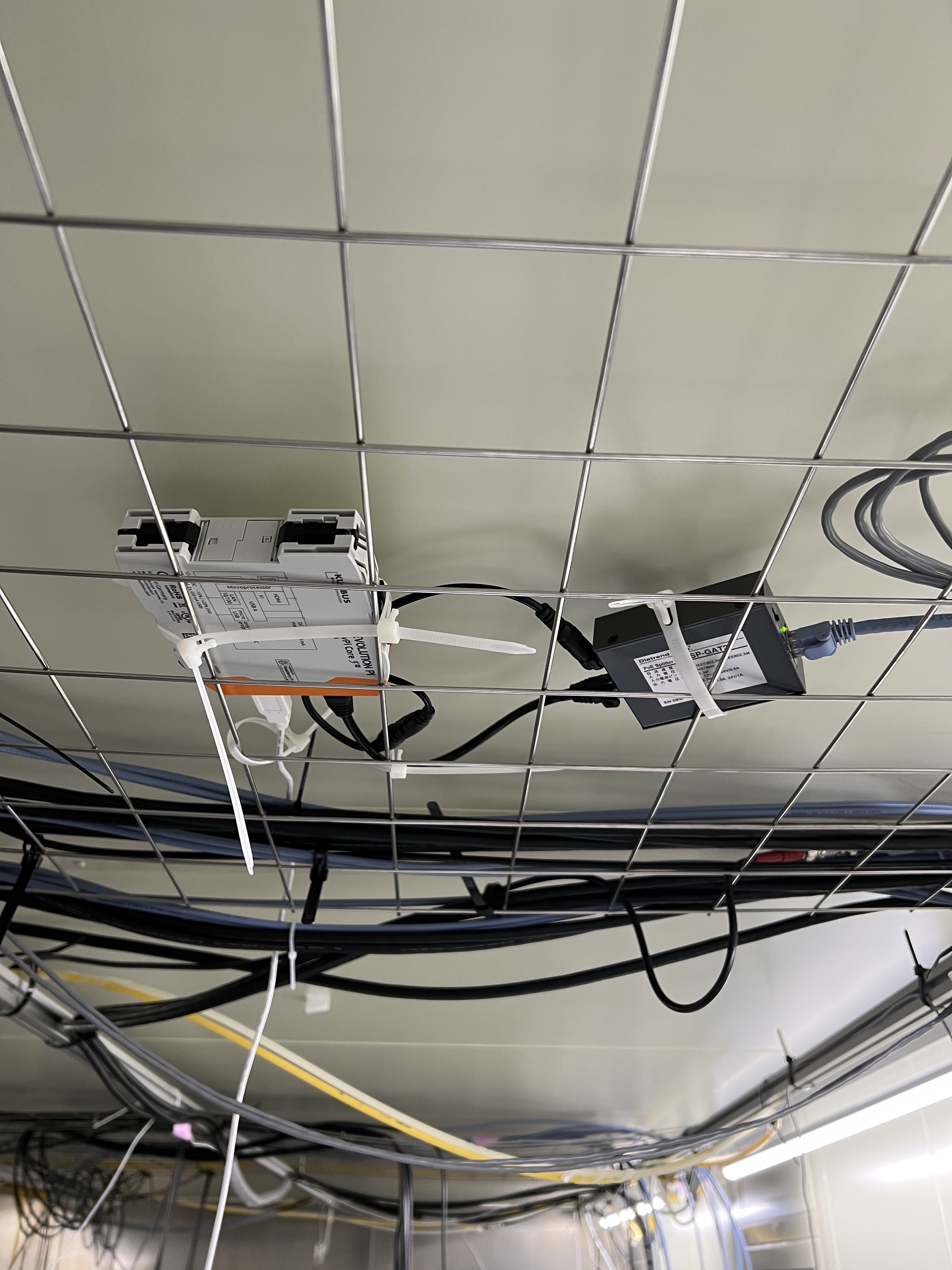
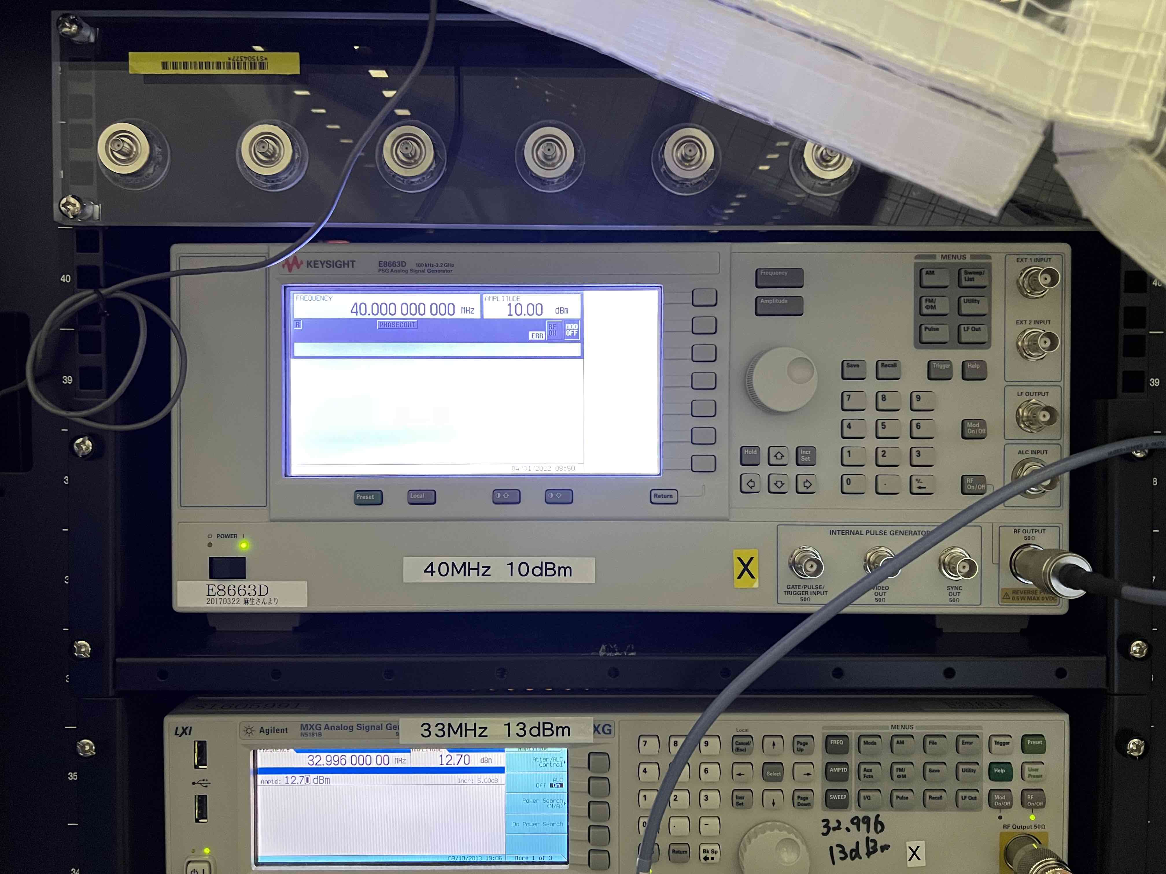
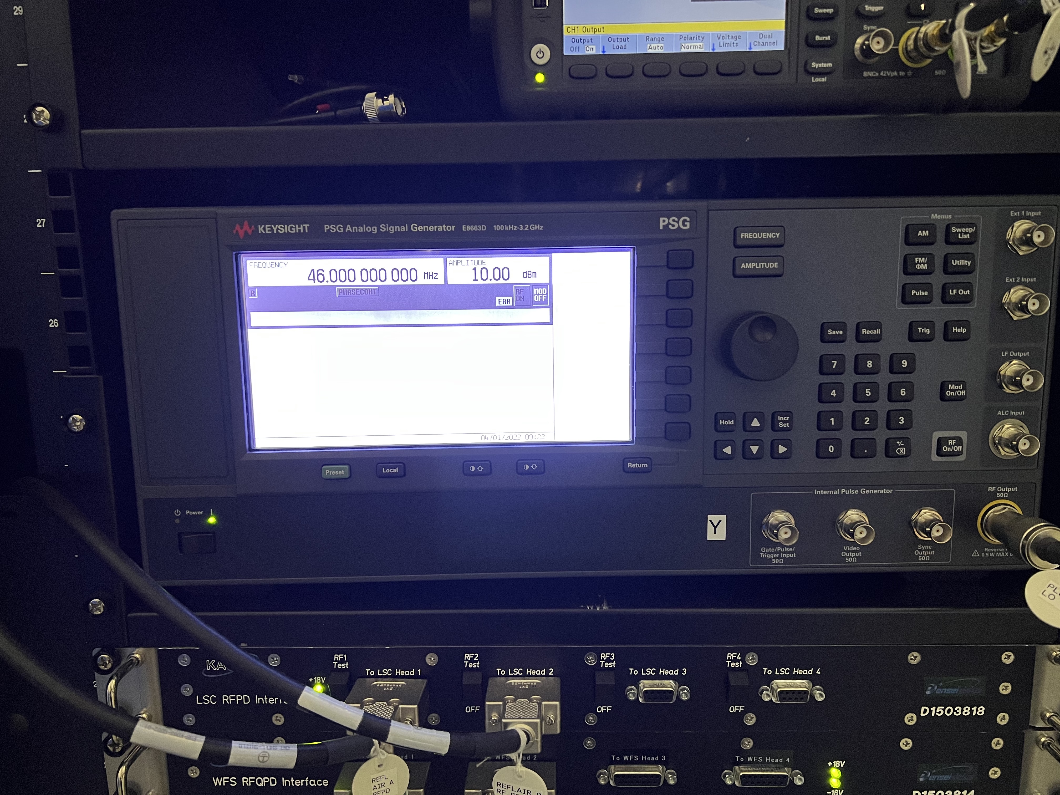
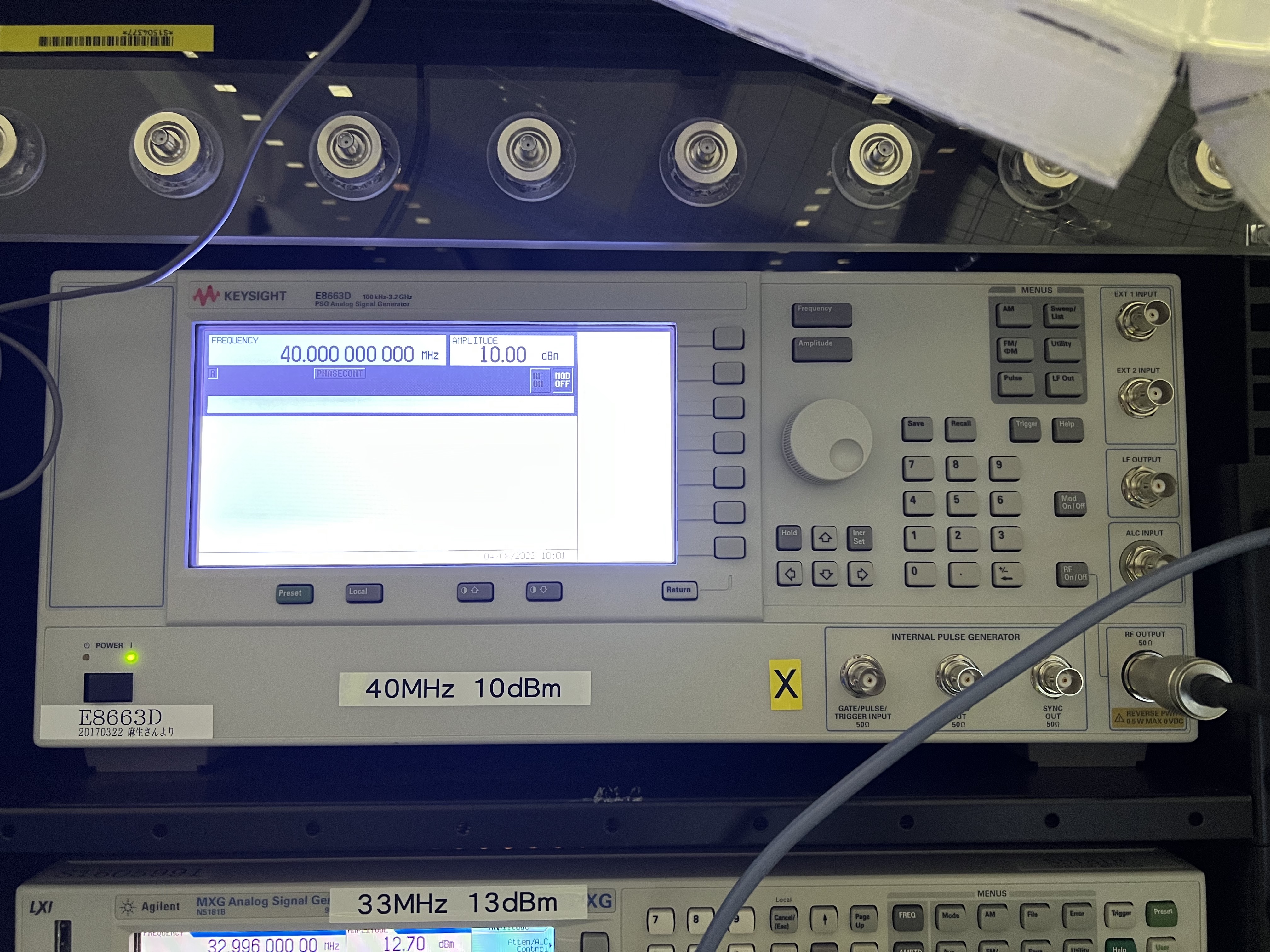
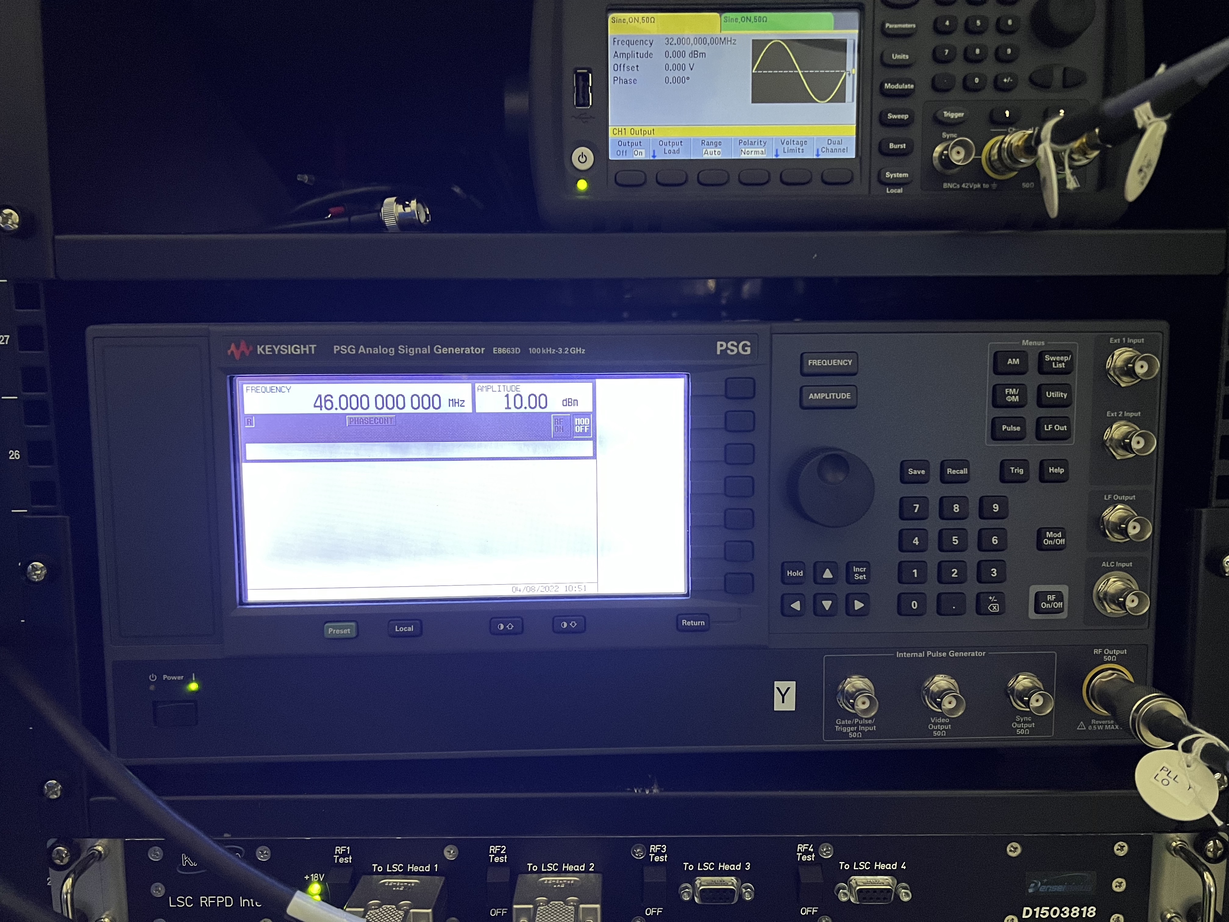
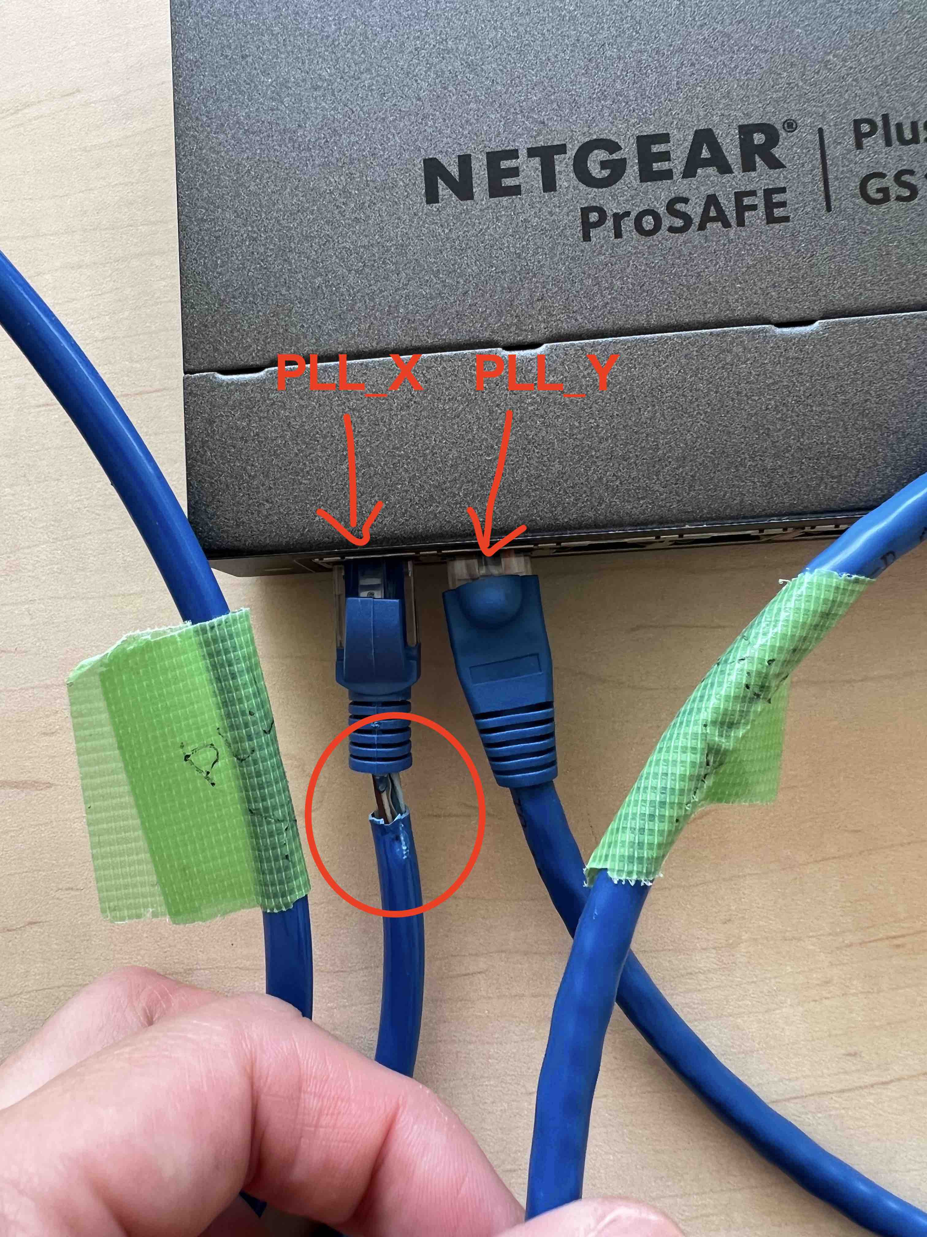
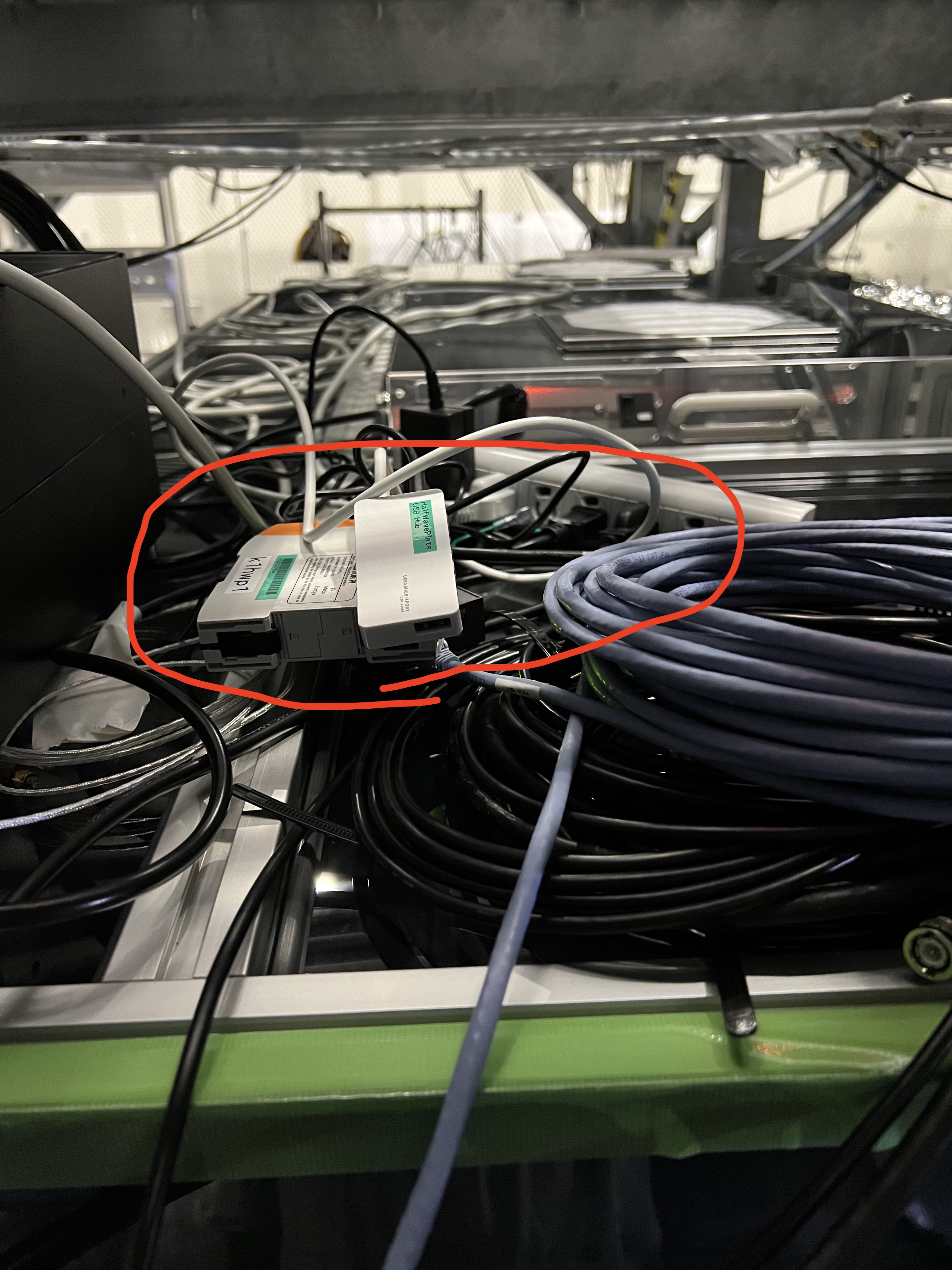
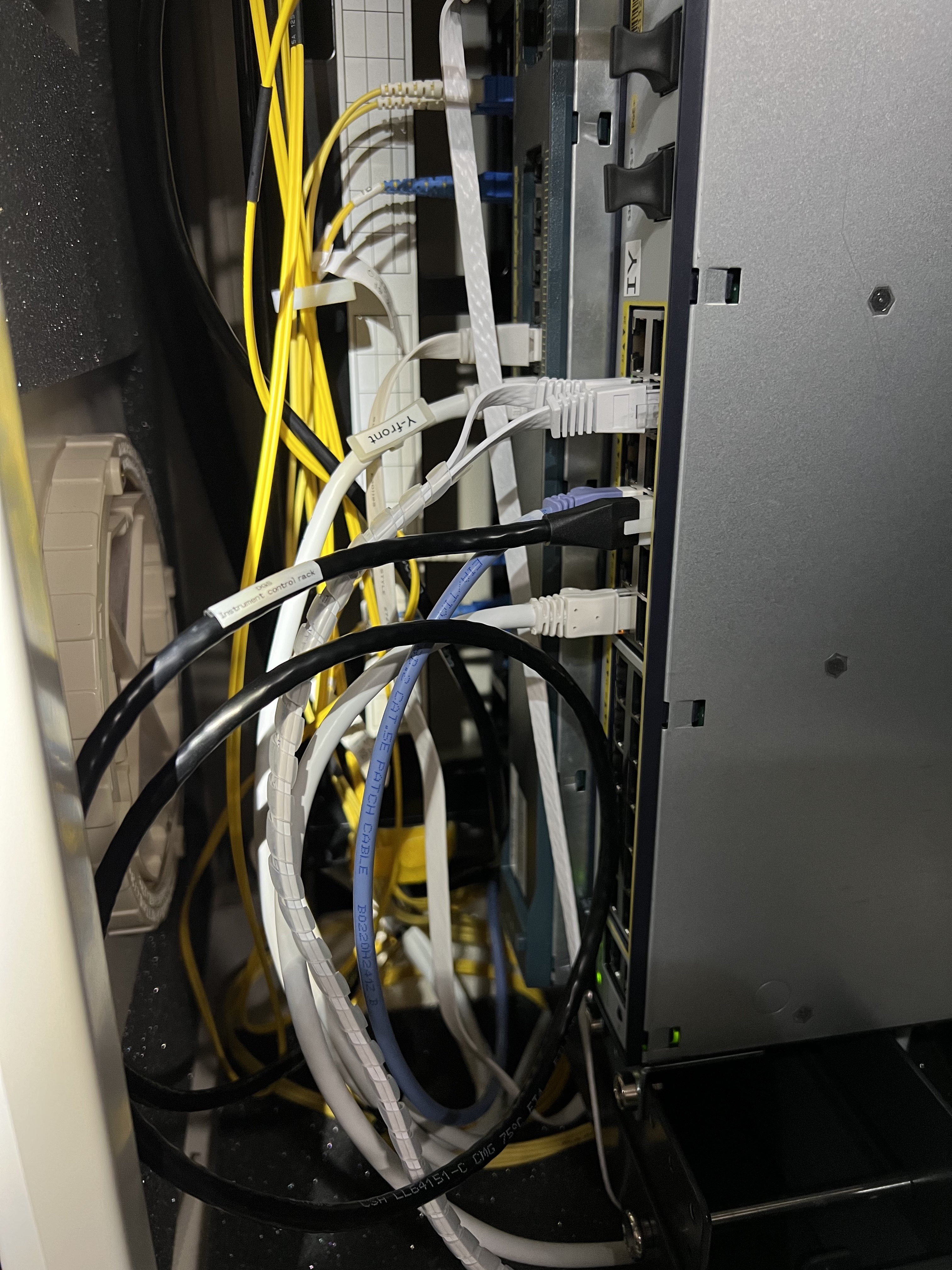
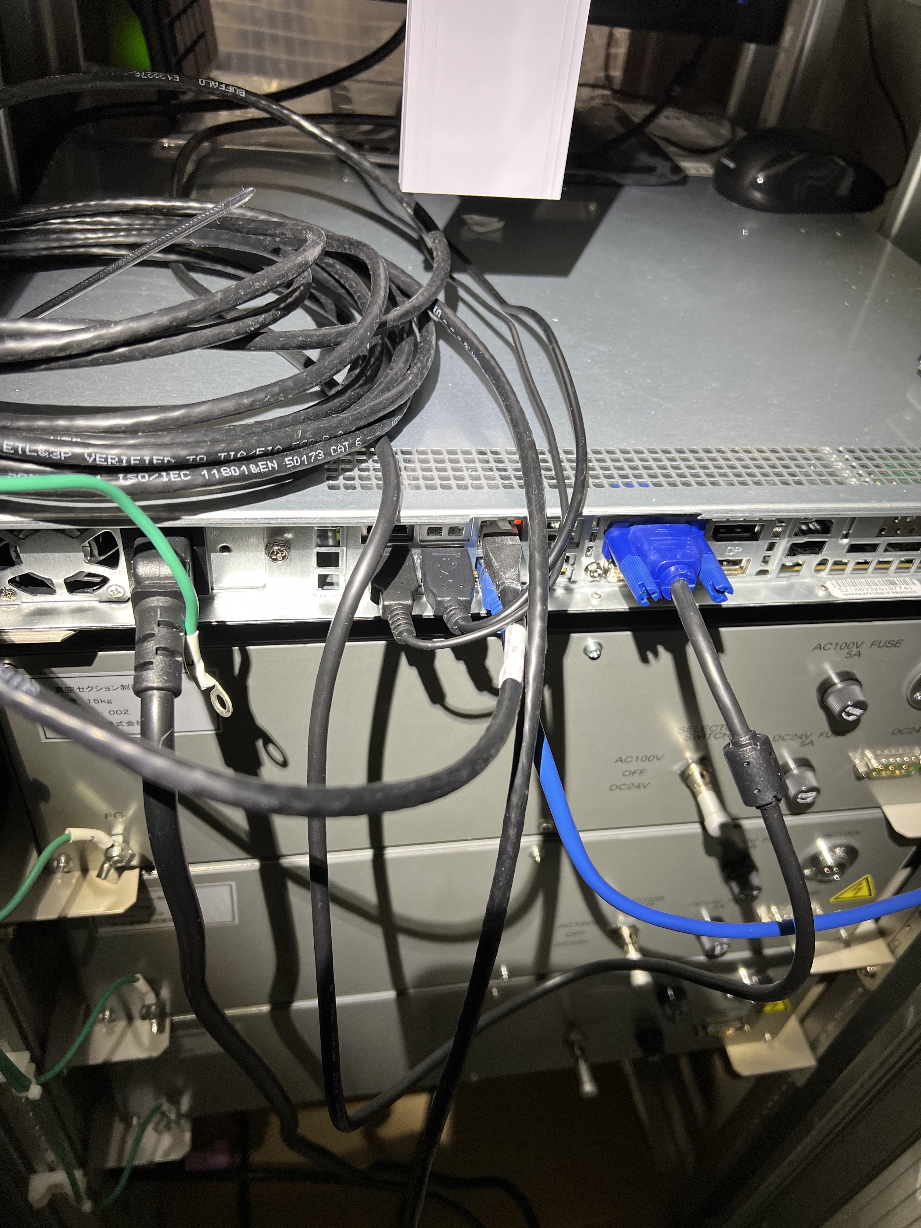
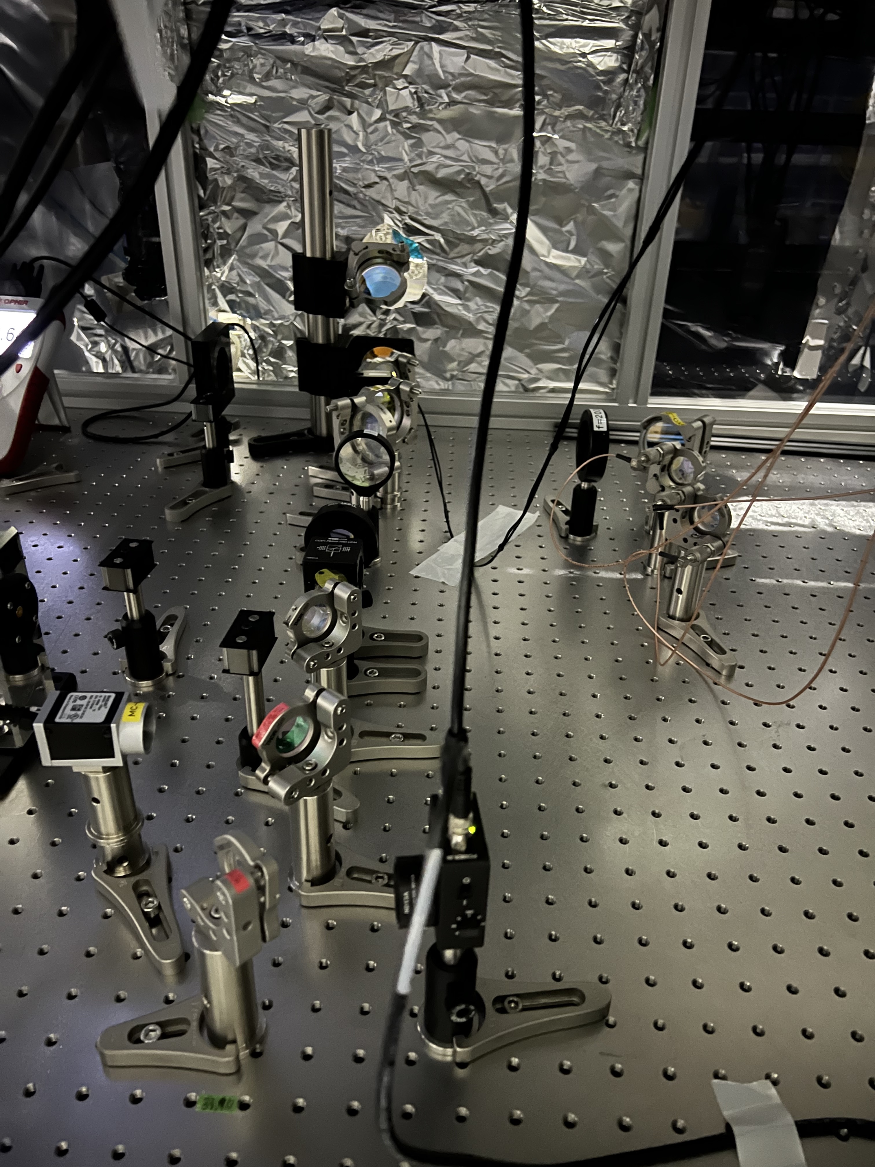
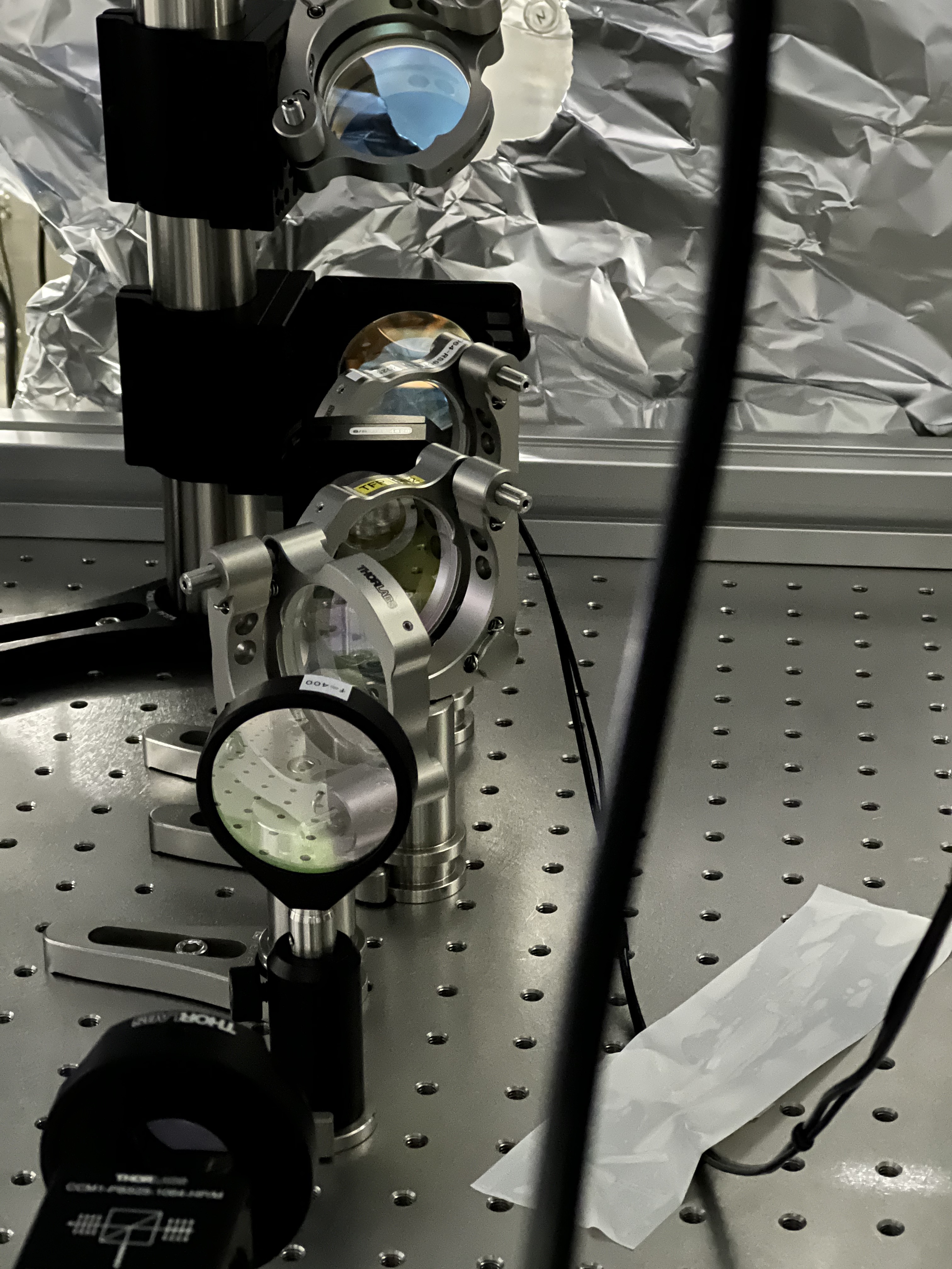
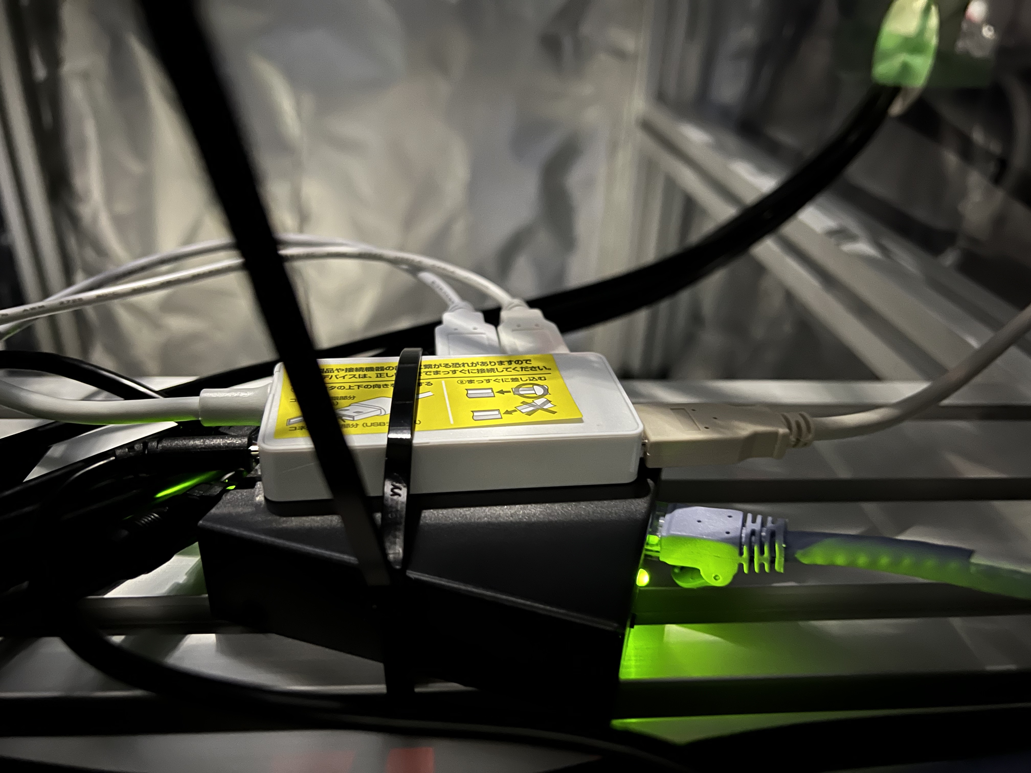
 Before starting the work, a picture of each was taken. (Fig.1, Fig.2)
 Changed Guardian for ALS_PLL_X and ALS_PLL_Y from PLL_LOCKED to SAFE.

 [PLL_X]
  1. unplug the LAN cable, press the [local] button
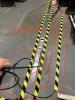
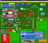
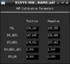
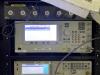
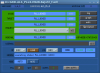
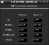
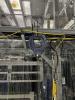
  2.[Utility]-[GPIB/RS-232 LAN] - [LAN Setip] (Fig.3)
   IP Addr: 10.68.150.65 -> 10.68.160.65
   Sub Net Mask: 255.255.0.0 -> 255.255.255.0
   Gateway: 10.68..0 -> 0.0.0.0.0
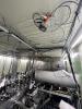
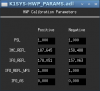
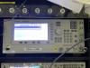
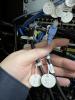
    Gateway needs to be set to 0 first, and
    If I try to set IP Addr and SubNetMask without changing them, the settings are forced to change to 127.0.0.1 and 0.0.0.0 due to inconsistencies. (Fig.4)     
  3. Press Frequency and Amplitude to adjust the settings.
   I made a mistake during the process, and miyoki-san helped me to correct it.

 [PLL_X]
  1. unplug the LAN cable and press the [local] button
  2.[Utility]-[GPIB/RS-232 LAN] - [LAN Setip]
   IP Addr: 10.68.150.66 -> 10.68.160.66
   Sub Net Mask: 255.255.0.0 -> 255.255.255.0
   Gateway: 0.0.0.0 -> 0.0.0.0.0
  3. Press Frequency and Amplitude to adjust the settings.

 Change Scripts
  /opt/rtcds/userapps/release/cds/common/scripts/epics-motor-control/keisight/
   freqmonitor_PLL.py
   pcas_pll.py
    Change each IP address

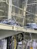
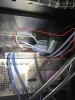
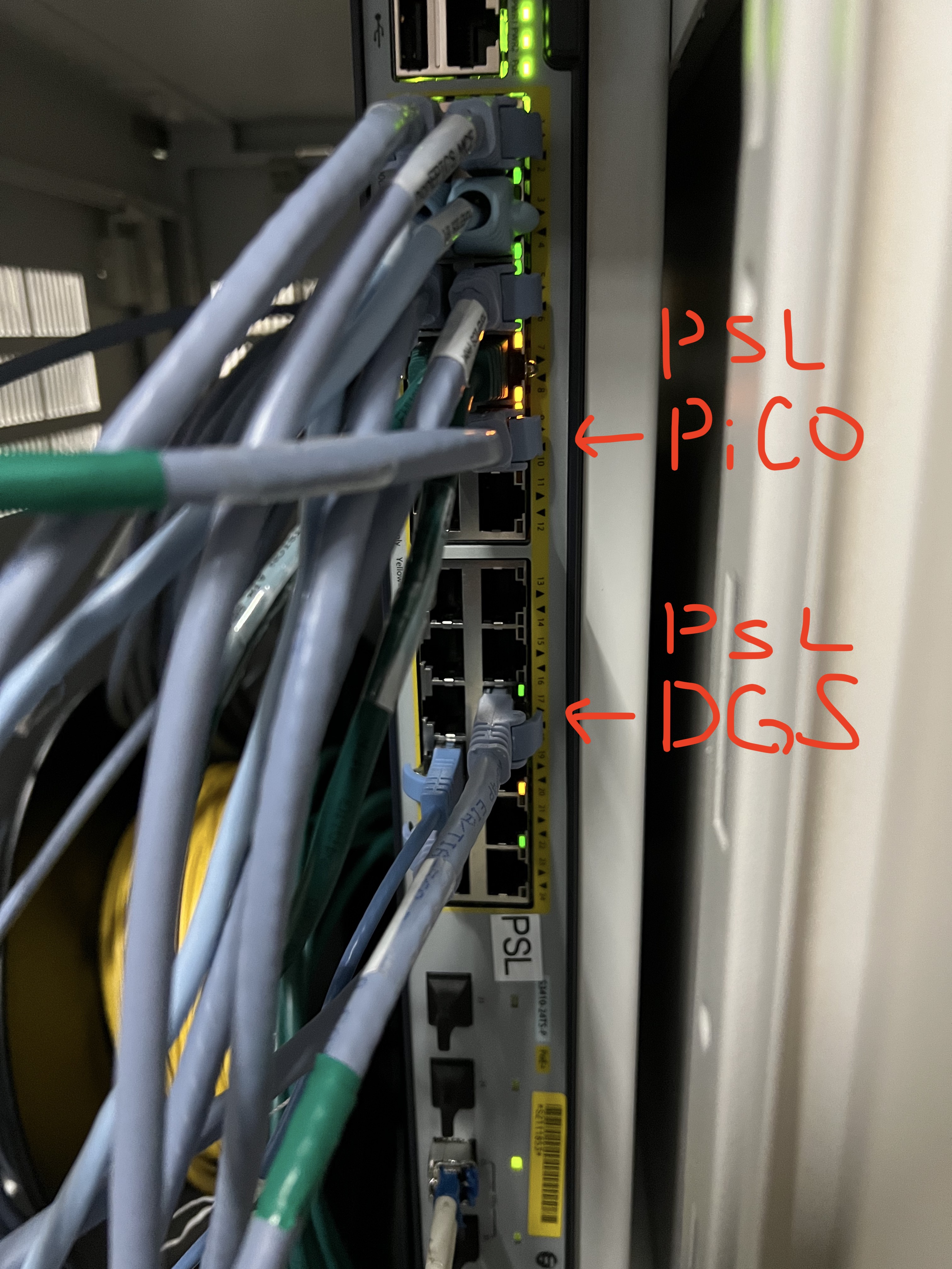
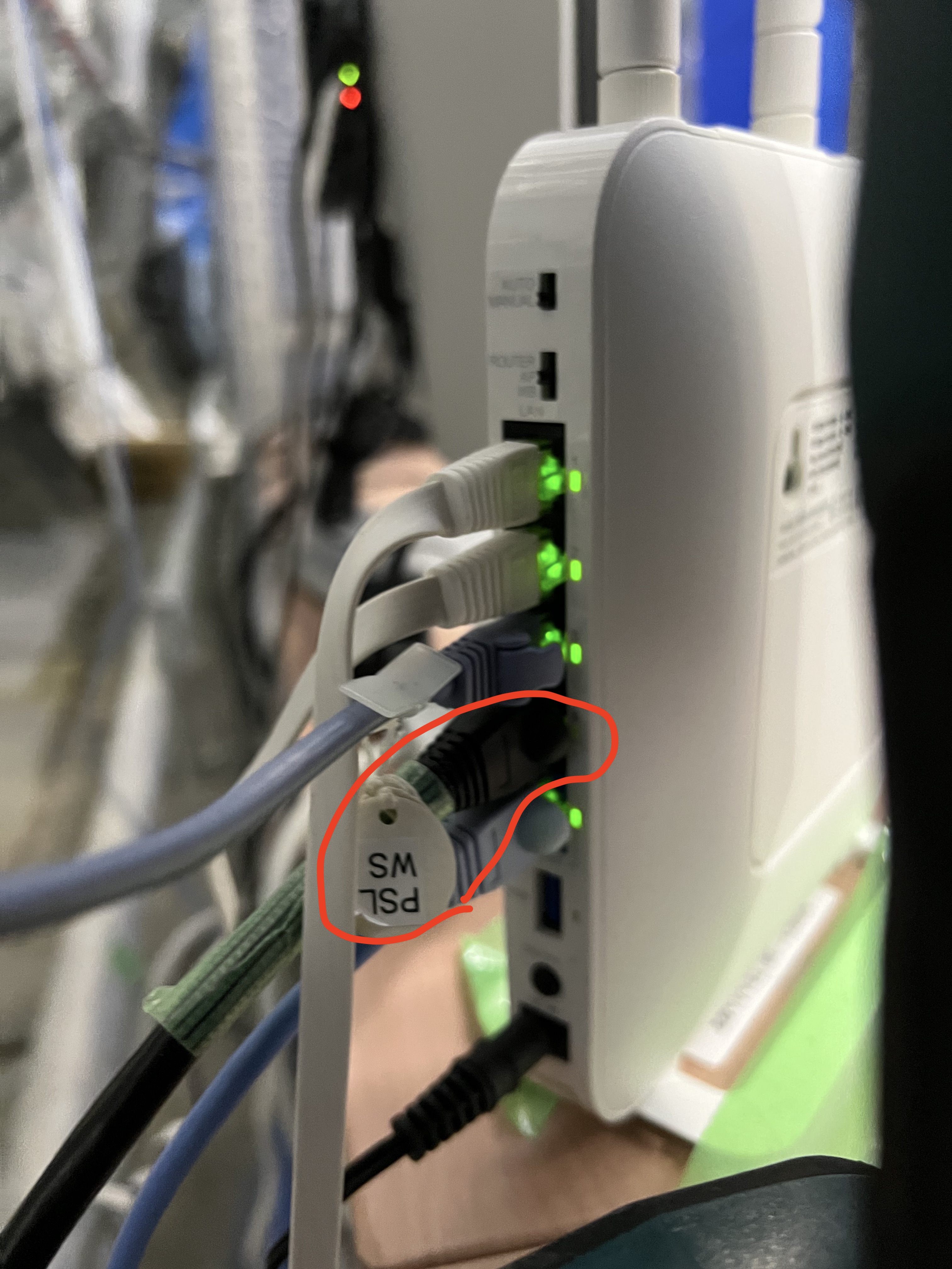
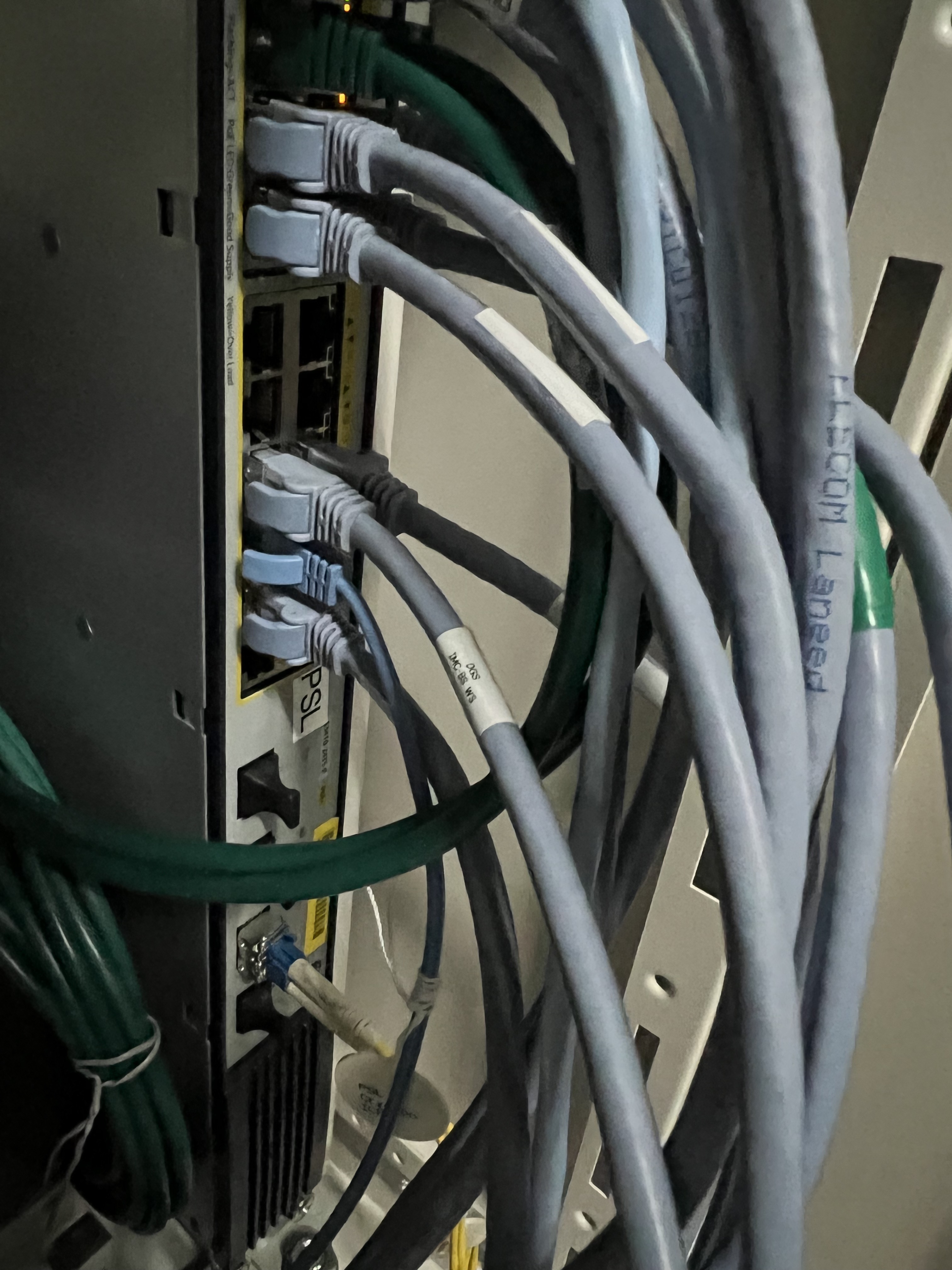
 LAN cable connection
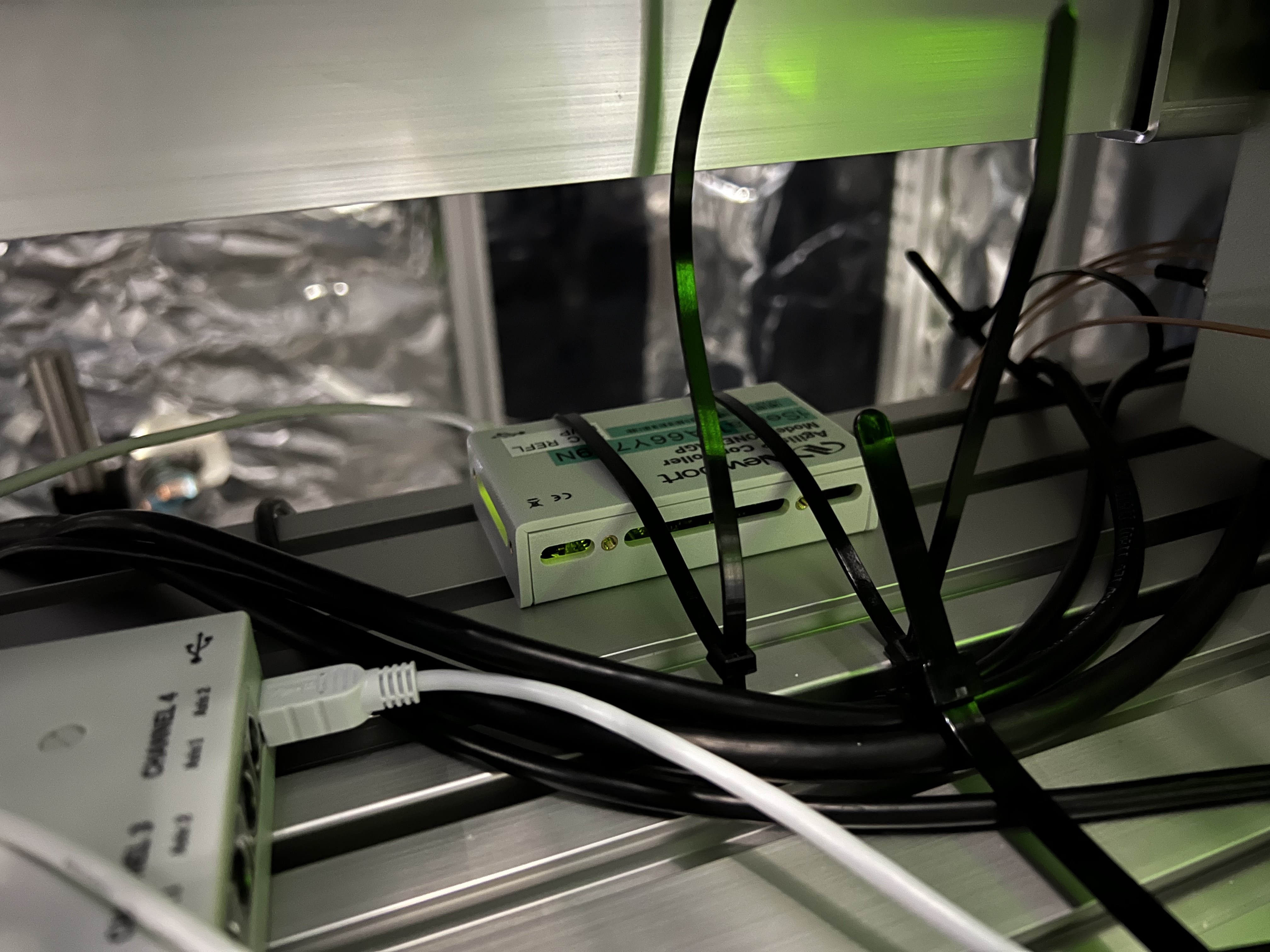
  LAN cable was connected to SW and FunctionGenerator behind PSL room.
  Port: 10 : X-side Function Generator
  Port: 12 : Y-side Function Generator

 Deamon
  sudo supervisorctl reload
   -> Daemon was restarted.
      I am using pyvisa in the conda environment, but it seems that the IP address remains in the conda environment if I only use read/stop/start, and there was a problem with not being able to connect using the PicoNet address.
      This problem was solved by re-starting the daemon.

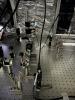
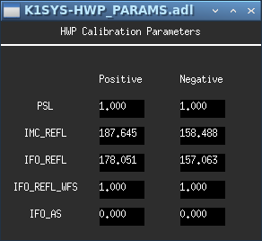
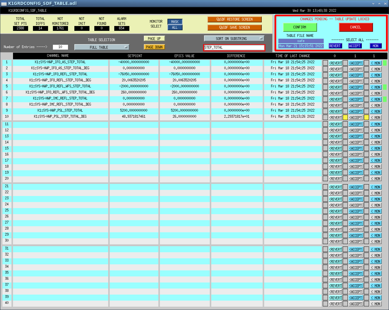
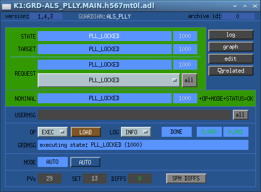
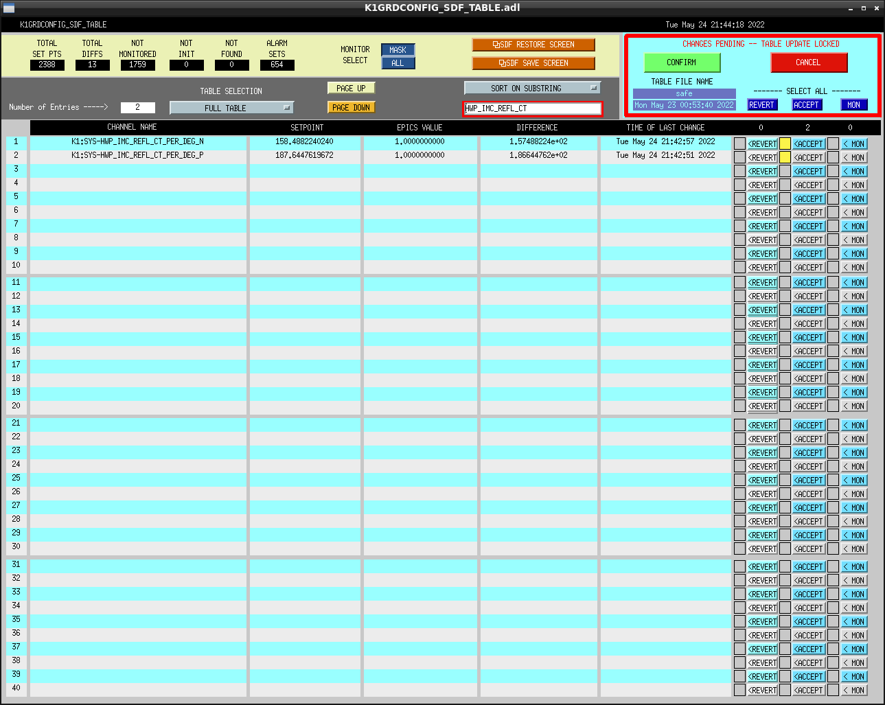
  We changed Guardian of ALS_PLL_X and ALS_PLL_Y from SAFE to PLL_LOCKED and confirmed that they are now locked normally.(Fig.5, Fig.6, Fig.7, Fig.8)

  All of Function Generator's migration work to Pico is now complete.
 

Images attached to this comment
Non-image files attached to this comment
satoru.ikeda - 14:59 Friday 08 April 2022 (20420) Print this report

I brought back to Mozumi the LAN cable and network switch used by Function Generator.

The cable used on the X side had a stripped membrane.
And this cable was the non-twisted LAN cable that I pointed out in K-Log#20008.

We think that this is probably one of the reasons why Function Generator is unstable.
 

Images attached to this comment
satoru.ikeda - 14:35 Thursday 19 May 2022 (20790) Print this report

IFO REFL and IMC REFL control PC for use with HWP installed.
It is not yet connected to the HWP.

Connected the LAN cable of the control PC to Port.11 of the network SW behind the PSL room.
This is used as PoE.

We will connect to HWP next time.
Until then, we will test it on the box of MC REFL Table. (Fig.1)
 

Images attached to this comment
Non-image files attached to this comment
satoru.ikeda - 18:11 Friday 20 May 2022 (20817) Print this report

[Ikeda, Yasui-san]

1. The network of WS in BS and IMC was connected from the 100Mbps SW in the computer room.
Therefore, we installed a 1Gbps LAN from the SW behind the PSL room and reconnected it.

 Before modification
  Computer Room N1 Rack SW -> BS sw -> IMC(IOO area) sw
 After modification :
  SW behind PSL room -> IMC(IOO area) sw -> BS sw 

 BS SW was changed to AC adapter instead of PoE power supply.
 It is connected to Port 18 of the SW behind the PSL room. (Fig-1)

2. Removal of network SW above the central rack
 This SW was also beaded from the 100Mbps SW in the computer room.
 This bead connection is very inefficient.
  BS SW -> SR2+SR2 2nd SW -> SRM SW -> SR3 & OMC SW
 Removed SWs are SR2 SW, SRM SW, SR3 SW and OMC SW. 

 Next equipment will be relocated to PICO net, so LAN cable is still there but SW was removed.
  PICO 
   OMMT1/OSTM
   AS WFS
   POS_POM

 The SW above the BS has not been removed.
 A POP/GREEN POM PICO was connected to this with power on.
 This will remain until these are relocated to the Pico network.

 A new LAN was connected from the SW in the machine room to the LAN in the Instrument Control Rack.
 It was connected to Port 18 of the SW on the Y side of the machine room. (Fig-2,3)

 The removed SW is placed on the shelf next to the BS WS. 
 

Images attached to this comment
Non-image files attached to this comment
satoru.ikeda - 18:11 Monday 23 May 2022 (20832) Print this report

[Ikeda, Tanaka-san, Yasui-san]

Summary
 Continuation of K-Log#20790
 I am replacing the HWPs of IFO REFL and IMC REFL with rotators with encoders.

 Today, we connected the control PC to IMC Table and installed the rotator with encoder to IFO RELF.
 Next time, we will change the rotator of IMC REFL.

WORK
 1. change K1:SYS-HWP_IFO_REFL_CT_PER_DEG_{P,N} to 1.0 and ACCEPT.
 2. after connecting the rotator and confirming that it works with the script, the installation work was done.
 The control PC was stored in the IMC Table side. 
 4. the rotator with encoder of IFO REFL was installed by Tanaka-san.
 The controller was fixed to a shelf inside the box. Fig.1 
 5. IMC REFL rotator with encoder is placed on the IMC REFL box.
  This will be installed next time.
 6. IFO_REFL_WFS is connected. However, this one has not been tested.
 Tanaka-san confirmed the operation of IFO REFL. Finally, we set the light intensity to the same as the original.
 
Addendum
 K1:SYS-HWP_PSL_CT_PER_DEG_{P,N} should have been changed in K-Log#20237, but it was back to the original.
 This was also changed to 1.0 again and ACCEPTed.

Images attached to this comment
Non-image files attached to this comment
satoru.ikeda - 18:23 Monday 23 May 2022 (20833) Print this report

[Ikeda, Yasui-san]

The following SWs and cables were removed.

Network SW on PR3 Rack
LAN cable that was connected to the SW on PR3
LAN cable from SW on BS Rack to SR2 Rack
The LAN cables from SRM to OMC and ASWFS were fixed to the +X side near OMC Rack because they require work at high places.

The LAN cable from BS to Instrument Control Rack is difficult to remove.

The remaining LAN cables are as follows.
POS_POM of SR2
LAN cable from OMC Rack to OSTM PICO and OMMT1 PICO
LAN cable from POP/GREEN POM PICO
Network SW above BS Rack

Non-image files attached to this comment
satoru.ikeda - 18:17 Wednesday 25 May 2022 (20882) Print this report

[Ikeda, Tanaka-san]

Summary
This is a continuation of K-Log#20832.
Replaced the MC REFL rotator with an encoder.
This completes the replacement of all requested HWPs.

Work
1. changed K1:SYS-HWP_IMC_REFL_CT_PER_DEG_{P,N} to 1.0 and ACCEPT.
2. shielded between MCF and IFI. (because we are working with BS) 
3. turned on laser to check output before working
4. replaced the rotator of MC REFL with one with encoder Fig1 and 2
5. after checking the operation, set HWP to the output of 3.
6. laser turned off and 2 above restored
7. fixed the motor driver to the shelf and the LAN cable to the cable rack Fig.3 to 6

Remarks.
∙ The total(deg) of PSL and IMC _REFL is almost zero for output at 0 and maximum at 45 deg.
 => k1:SYS-HWP_{PSL,IMC_REFL}_STEP_TOTAL_DEG

Total(deg) of IFO_REFL is not aligned to 0 position.
 => k1:SYS-HWP_IFO_REFL_STEP_TOTAL_DEG

IFO_REFL_WFS has been connected to the PC for control, but I have not checked the operation.

Images attached to this comment
Non-image files attached to this comment
satoru.ikeda - 16:53 Friday 27 May 2022 (20917) Print this report

The network switches on the BS Rack were also removed.
All network switches on the central Rack have now been removed.

The following LAN cables were unplugged from the 100 Mbps SW on the N1 Rack in the computer roomFig-1
N1 40 SW P3 BS SW P1
N1 40 SW P1 PR3 SW IN
 

Images attached to this comment
Non-image files attached to this comment
Search Help
×

Warning

×