With the transfer function models I generated from 19143, I generated corresponding control filters based on simple algorithms that I created.
The method is similar to that I used to make damping filters for SR3 in 17957 but is different.
Here I briefly describe what the algorithms do.
- Decompose the transfer function into a superposition of single-mode transfer functions.
- Find the dominant mode and sum it with all the modes with higher frequencies and get a new transfer function.
- A critical damping gain can be estimated from the DC gain and the frequency of the dominant mode (see 17957).
Alternatively, I have another algorithm to find the perfect damping gain such that the dominant complex pole pair become a pair of simple poles. It's better but it doesn't work for some special cases (we won't go into details here). - (For stages that needs DC control) Find proportional gain and integral gain that matches the lowest UGF of the damping OLTF. Alternatively, specify a target time constant and DC gain for them.
- (Optional) Find notch filters that cancel perfectly the resonances that we don't want to damp, i.e. those that are far from the main resonance.
- Find cut-off frequency of a low-pass filter to reach a specified phase margin using a bisection method.
The methods are all coded in my public Python library Kontrol. It can also be used to generate Foton filter expressions.
Notebooks used to generate the filters are available at /kagra/Dropbox/Subsystems/vis/vis_comissioning/sr2/notebook/control/.
This method resulted in extremely consistent filter designs with very minimal specifications.
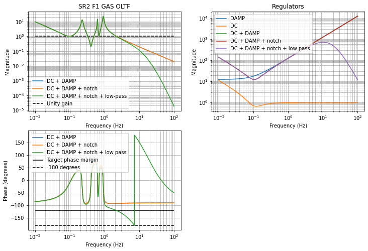
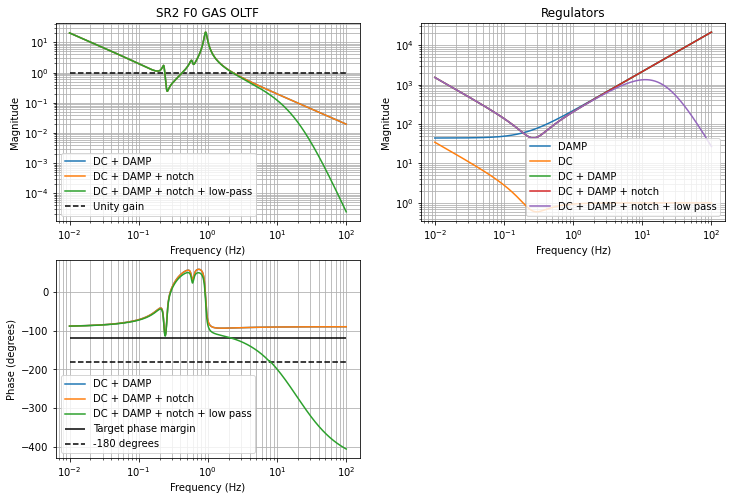
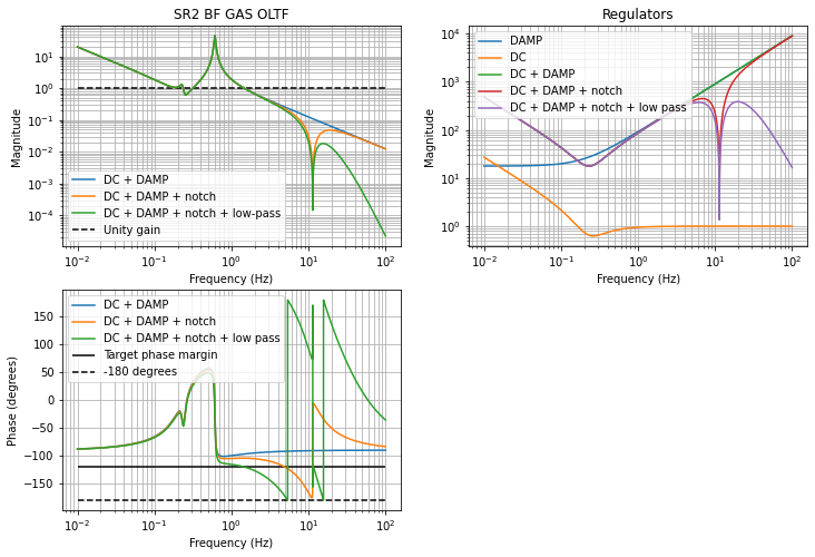
The default low-pass filter is a simple 2nd-order filter, which is just enough to roll off the f^1 control filter. In the case of GAS stages, they are 4th-order filters. This is to account for the f^2 actuation coupling at above 10 Hz.
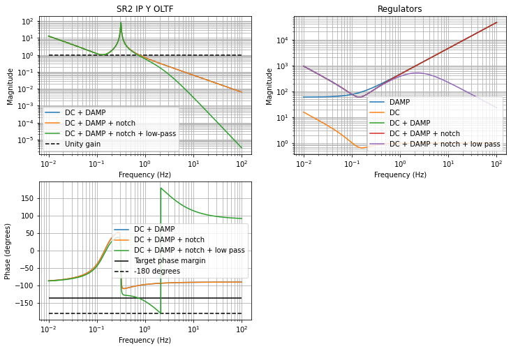
The default target phase margins for all loops are 45 degrees. In the case of GAS stages, they are 60 degrees to account for the unmodelled actuation coupling.
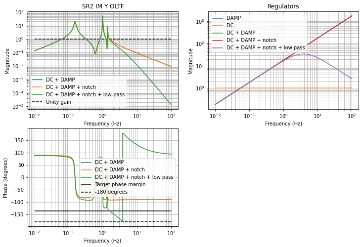
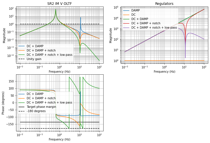
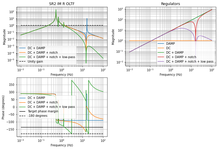
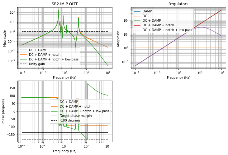
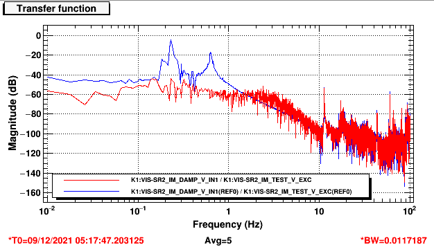
The resonance peaks above 10 Hz in the BF V, IM V, IM R, and IM P are notched so they are not damped.
Also, note that the 11 Hz peak in the BF V transfer function was not modeled so I simply copied the notch filter from the IM V loop.
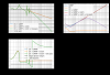
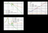
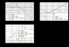
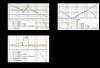
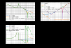
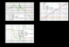
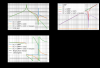
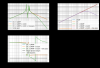
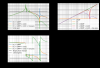
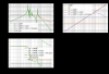
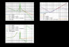
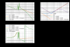
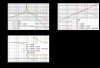
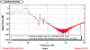
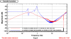
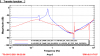
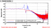
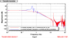
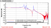
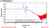
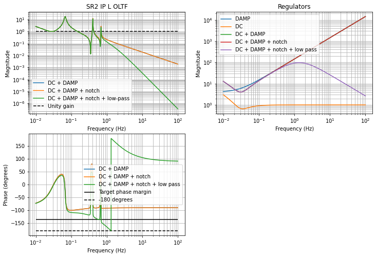
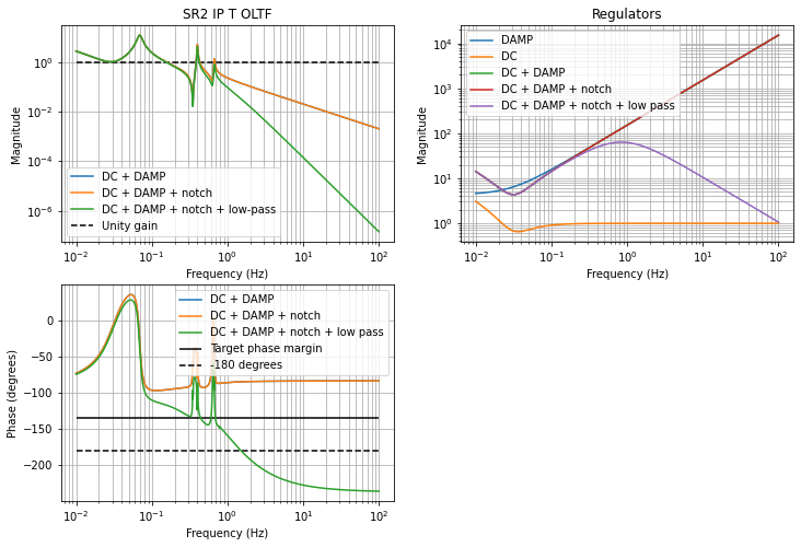
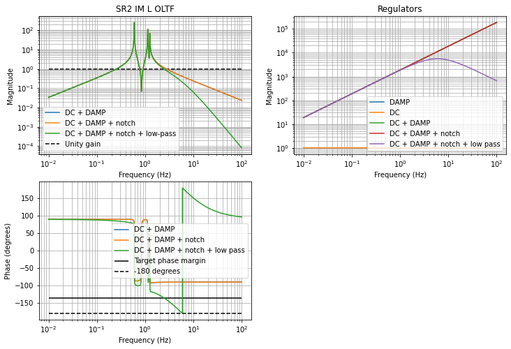
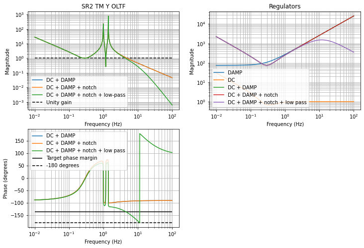
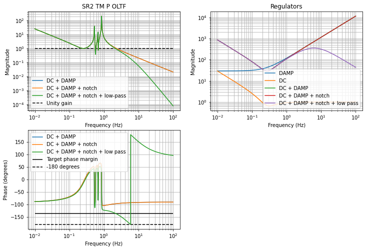
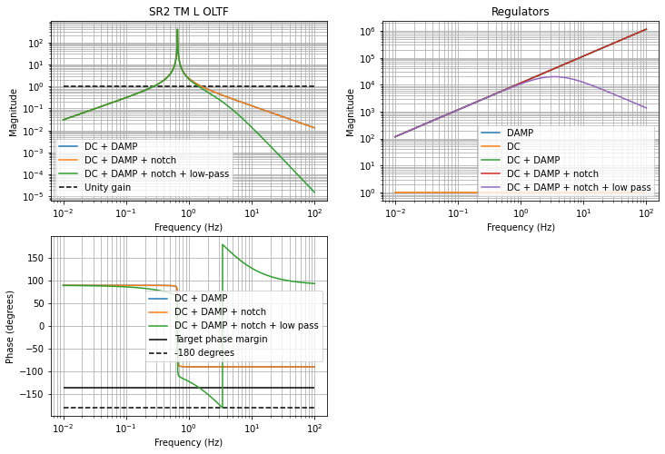
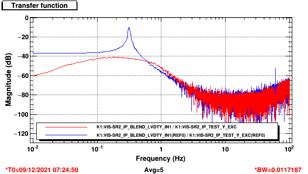
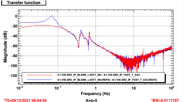
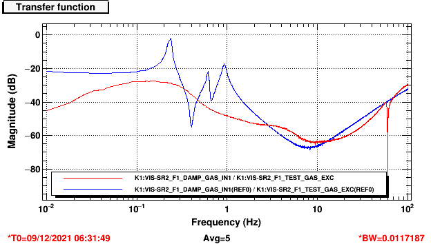
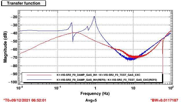
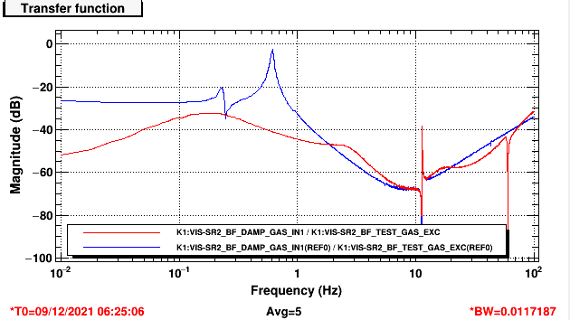
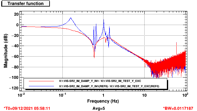
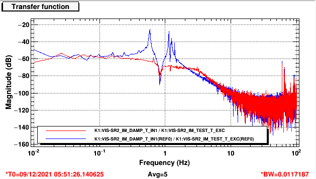
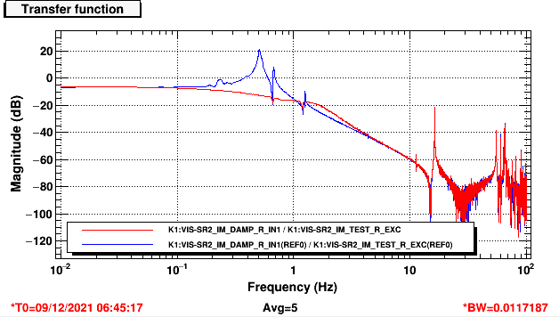
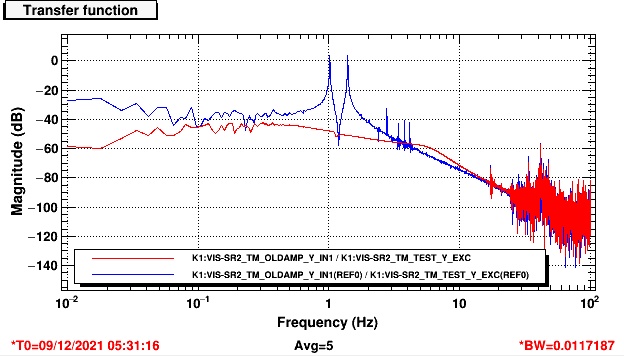
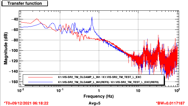
Figures shows the OLTF and the filters of all DoFs. note that the filters are decomposed into Foton-friendly damping filters and DC filters.
DAMP (and low-pass) filter are installed in FM3 of the filters, DC filters are in FM4, and notch filters are in FM5 of the filter banks.
Important note: These are damping loops for fast and stable steering during lock acquisition and alignment.
Seismic noise and sensor noises were not taken into account whatsoever. And, geophones are not used.
The optimization of these filters for seismic isolation during observation tends to be tedious and I will do this at a later stage.
Some control performance will be posted in a later klog.


