Using the transfer functions fitted in 17956, I constructed damping control filters for all degrees of freedom.
The logic behind the filters are as follows:
Since we have decomposed the transfer function into a superposition of oscillators in 17956, we can pick out the dominant mode, which has static gain and resonance frequency
.
For velocity damping control on a single oscillator, the closed-loop system will be critically damped at
So, that's the gain that we set for each DoF. In reality, this gain will slightly overdamp the system is typically not a simple oscillator.
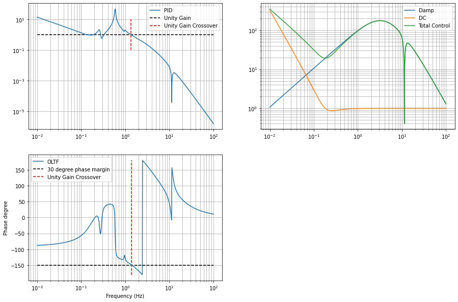
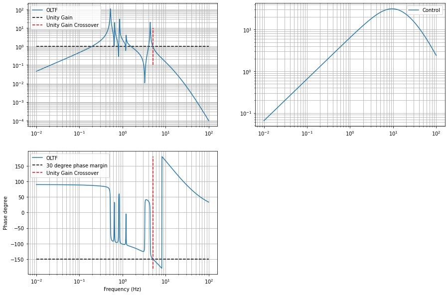
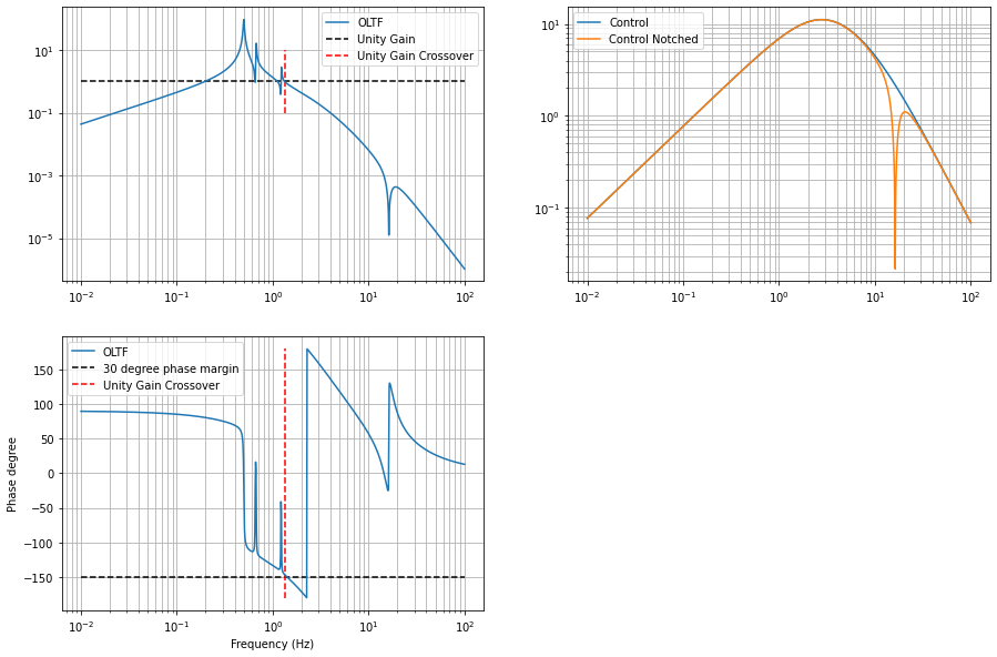
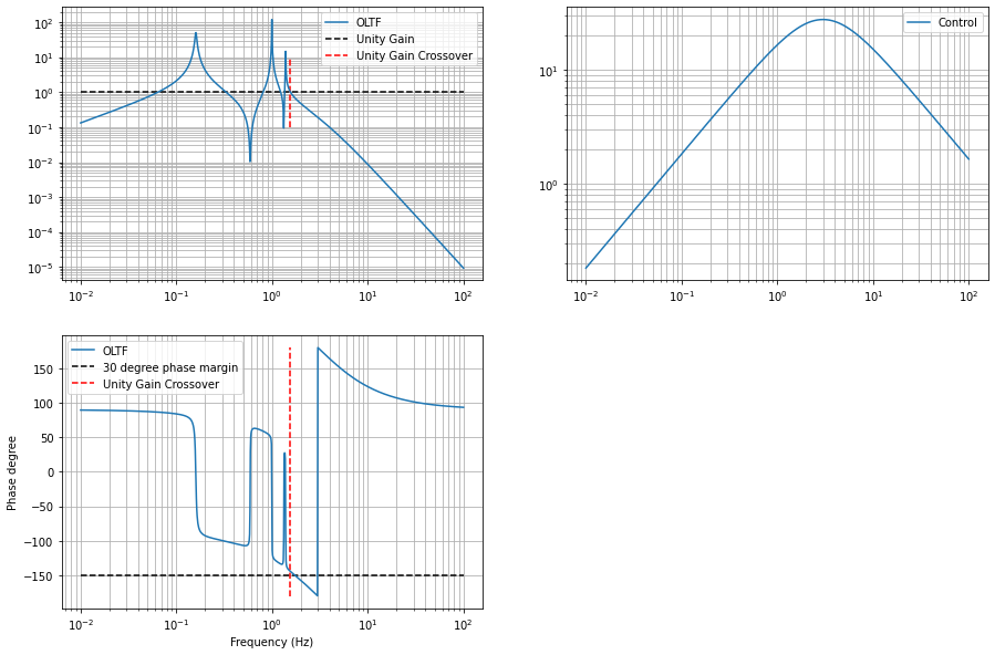
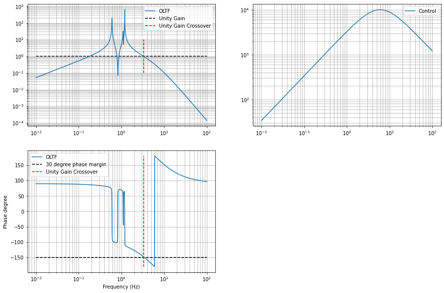
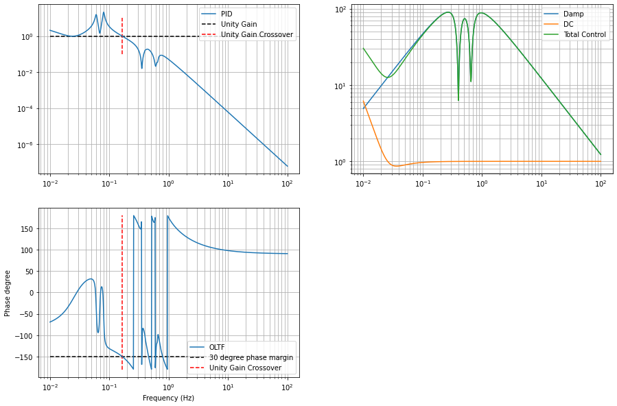
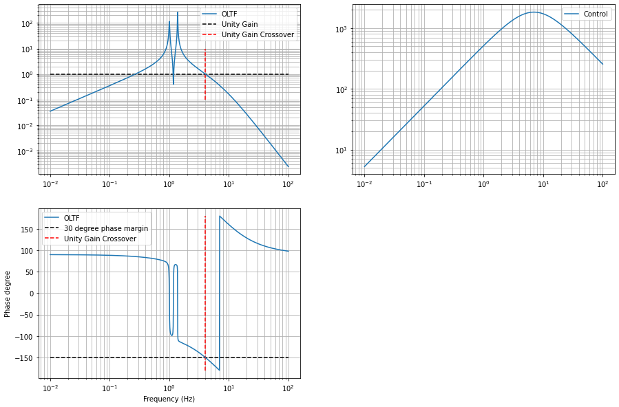
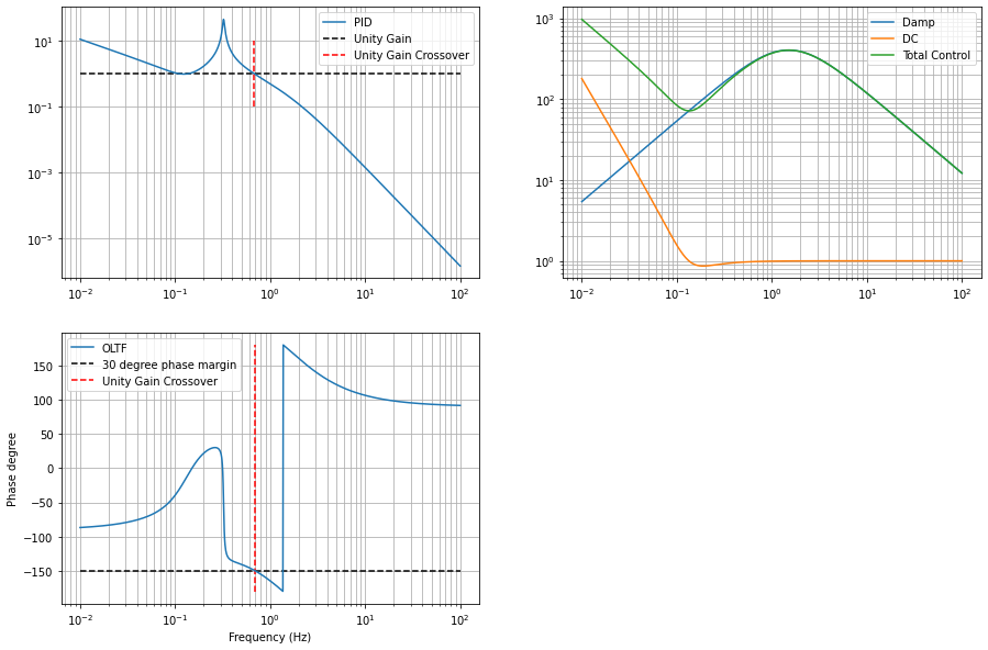
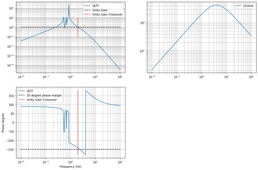
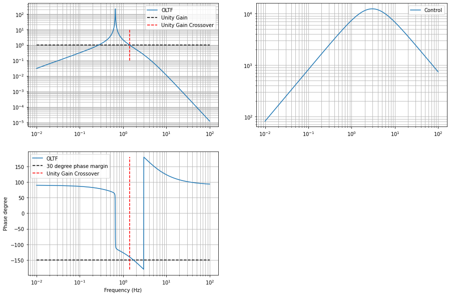
After that, we added second-order low-pass filters and we do so that the phase margin is around or greater 30 degrees. For GAS filters and DoFs that uses vertical OSEMs, there's an additional low-pass at higher frequencies to filter the stranger responses at higher frequencies.
The damping filters are placed in FM4 of each damping filter.
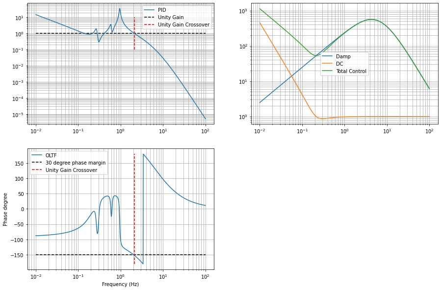
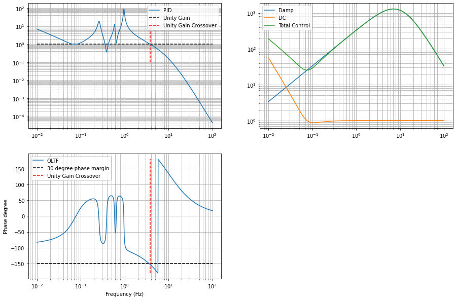
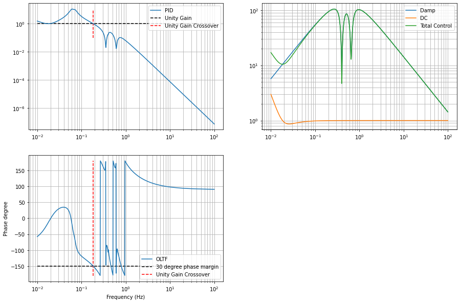
For stages that require DC control, we consider a PID configuration with controller
.
We set the derivative gain using the criterion above. For the integrator, we set the gain such that the integral control alone has UGF equal to the lowest UGF of the damping control.
This integrator gain corresponds to the maximum integral control gain at which it doesn't interfere with the damping control.
The proportional gain is set in a similar fashion. This way, the open-loop transfer function at lower frequencies will be right above unity gain but damping control at higher frequencies is remain unchanged.
Since we don't have parallel filter banks in the control system, the additional controls that accounts for the intergral and proportional action must be placed in series to the damping control.
This filter is defined by
.
So the total will be , which is the designed one.
The DC controls were placed in FM3 of the filter banks.
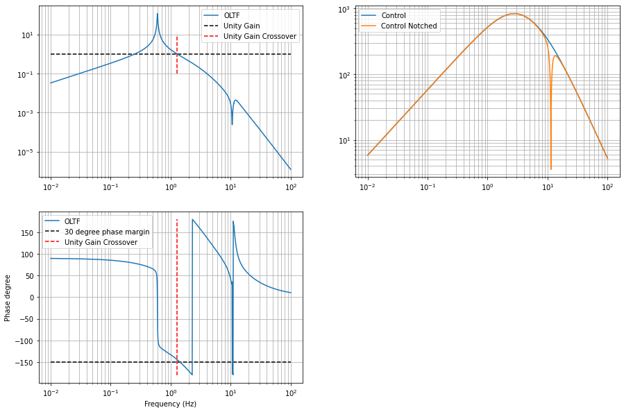
In addition, some DoFs have higher resonances that appears higher than the UGF of the open-loop transfer fucntions. These are notched out to avoid instabilities. The notch filters were placed in FM5 of the filter bank.
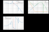
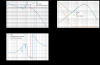
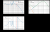
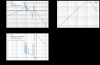
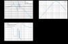
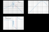
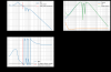
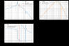
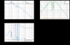
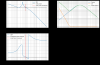
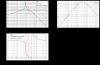
The attached figures show the OLTFs and the control filters of each DoF. Sorry I didn't label the plots for each DoFs. The DoF is specified in the file names.
All filters were analysed and generated from Jupyter notebooks at /kagra/Dropbox/Subsystems/VIS/vis_commissioning/sr3/notebook/control/.
In the notebooks, you will also find utility functions that I made in my kontrol python package that generates foton strings from Python TransferFunction objects, which can be copied to foton directly.
All controls were engaged for 4 hours+ yesterday without any issues.


