Reports 1-1 of 1 Clear search Modify search
VIS (BS)
fabian.arellano - 18:05 Wednesday 08 September 2021 (18191) Print this report
In-vacuum cable health check at outer side of flanges.

With Tomaru, Yano, Yasui, Hirata.

Tomaru-san and Yano-san checked the in-vacuum cable health by measuring with a multimeter at the outer side of the flanges.

They found a problem of concern: pins 1 and 6 in the F1 LVDT connector have conductive paths with the chamber. The primary coil with the reference signal is connected to these pins (D1503600-v16 , page 5).

I checked the status of the LVDT and coil-magnet actuator by measuring a transfer function: the measurement does not seem too bad but it has an unusual notch at 1 Hz, close to where a peak was expected.

I also noticed that the LVDT reading is very high, namely, around 1.2 mm. We checked the recorded data and found a big jump on the 18th of July. A jump also happened on the 18th of June.

They also found other pins connected to the chamber, but this condition does no have any important consequence. I'll comment on those in a future entry.

Images attached to this report
Non-image files attached to this report
Comments to this report:
fabian.arellano - 16:42 Thursday 09 September 2021 (18213) Print this report

With Hirata-san.

  • Today we added the values of the thermistor resistances (PT-100) and
  • We double-checked the values of some resistances that had been reported possibly oscillating. We found them stable.
  • More comments will follow.
Non-image files attached to this comment
fabian.arellano - 16:00 Tuesday 14 September 2021 (18251) Print this report

With Hirata-san.

Topic: this entry is about the primary coil of the BF F1 LVDT having a connection with the chamber.

Summary: We still don't know whether the problem is within the in-vacuum connector which connects to the flange or at the level of the F1 filter inside of the chamber.

We opened the vacuum chamber and examined the cable assembly as follows:

  • We disconnected the in-vacuum connector from the flange.
  • Then we removed the two layers of aluminium foil that we wrapped around the connector and the cable for mechanical support.
  • We discovered pin 1 broke apart from its thread. Then we checked the connection between pins 6 (LVDT primary) and 5 (chamber and ground) and found a conductive path. This suggests that the pin directly connected to the chamber is 6 and not 1.
  • We connected pin 1 to the cable thread again.

Because we were measuring directly at the in-vacuum connector, and this cable goes all the way down to the F1 filter, first we thought the problem had to be at the filter level. However, during a second assessment, we realized the resistance between pins 5 and 6 changed from a value of several MOhm to around 10 Ohm, and all we had manipulated so far was the position of the connector. This suggests that the problem might at the connector itself.

We should examine whether the cable thread connected to pin 6 is touching its shield or not. We'll likely need to remove the pin from the connector.

fabian.arellano - 15:27 Wednesday 15 September 2021 (18264) Print this report

With Hirata-san.

Summary: The unwanted conductive path between the F1 LVDT primary coil seems to happen at the level of the F1 Filter, not at the level of the IP.

Yesterday we suspected the conductive path between pins 1 and 6 of the BS F1 LVDT with the chamber were happening at the in-vacuum connector that is plugged to the flange at the IP level. Today I explored this hypothesis.

We removed pins 1 and 6 from the connector case and measured the resistance values directly at the pins: the conductive path was still there, therefore indicating that the problem is at the F1 GAS Filter level. Unfortunately, this means we need, at least, to lift the whole suspension from the chamber to inspect the connector on top of the F1 Filter.

The values of the resistances measured in the morning were:

  • Pins 1, 6: 198 Ohm
  • Pins 6 and chamber: 10 Ohm.
  • Pins 1 and chamber: 202 Ohm.

In the afternoon Hirata-sa confirmed these measurements.

These values suggest that the thread connected to pin 6 is the one directly connected to the chamber. Pin 1 is connected to the chamber indirectly through the coil.

With respect to the stability of the resistance values, they seem stable now. Yesterday we measured MOhms one time but we haven't been able to reproduce the value, so we believe we made a mistake that time.

fabian.arellano - 17:55 Wednesday 29 September 2021 (18393) Print this report

With Hirata-san.

Today we checked the cables of the F0 yaw stepper motor. The resistance between pins 2 and 7 were larger than expected (13.4 Ohm vs. ~8.5 Ohm).

A couple of weeks ago we found that the problem was at the pins connecting the kapton coated wires coming from the stepper motor, to an extension cable. At that time we moved the pins and the resistance dropped to an acceptable value, but we didn't check in detail.

Today we checked again, but were unable to reproduce the problem. The resistance is 8.04 Ohm and is very stable despite that we moved the wires a lot. It seems thah problem is gone.


fabian.arellano - 10:54 Tuesday 09 November 2021 (18805) Print this report

With Hirata-san.

We measured the resistances of LVDT coils at the cables connected to the front of the GAS filter LVDT driver.

Pins GAS IN (Ohm), left connector GAS OUT (Ohm), right connector
1, 6 209.5 87.2
2, 7 203.0 83.0
3,8 201.0 81.8

Observations:

  • The higher values correspond to coils connected to pins 1 and 6 of their corresponding LVDT cables. Given the higher values, these are likely secondary coils. They are also connected to the left side of the board, where the signal demodulation happens.
  • The lower values correspond to coils connectedto pins 2 and 7 of their corresponding LVDT cables. These are likely primary coils. They are connected to the right side of the board, where the components related with the reference signal are.

This examination indicates that the connection that is failing in the F1 LVDT is not at the primary coil, but at the secondary one.

Images attached to this comment
fabian.arellano - 17:34 Wednesday 17 November 2021 (18924) Print this report

With Hirata-san and Yano-san.

See pictures in the album BS Remedying work after O3.

Summary: we replaced the LVDT driver card for the GAS Filters for a new one which has been prepared to reduce the noise. We haven't installed the driver in the rack yet, therefore, the BS suspension is out of order now.

  • See the ICs within the blue rectangle in the first screenshot. There is an additional connection in each.
  • We removed the old card and, for each channel, we measured the resistances determining the amplitude of the reference signal, the amplitude of the return signal from the LVDT and the phase between the two. The resistance values are shown in the notes in the second screenshot.
  • In the new board, we adjusted the resistances according to the measured values.
  • We will install the driver in the rack tomorrow.
Images attached to this comment
fabian.arellano - 13:52 Thursday 18 November 2021 (18933) Print this report

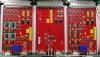
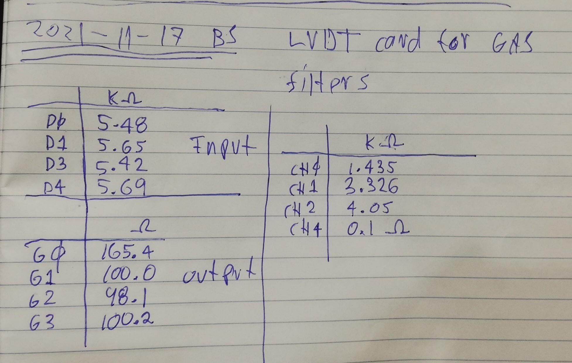
GAS  filter  LVDT  card  replacement

Summary:  the  new  LVDT  card  seems  to  be  working  fine,  but  the  calibration  factors  and  offsets  seem  to  require  adjustment.

After the  replacement  of  the  LVDT  card  for  the  GAS  filters,  I  chracterized  the  health  of  the  LVDTs  using  transfer  fuction  measurements.
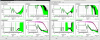
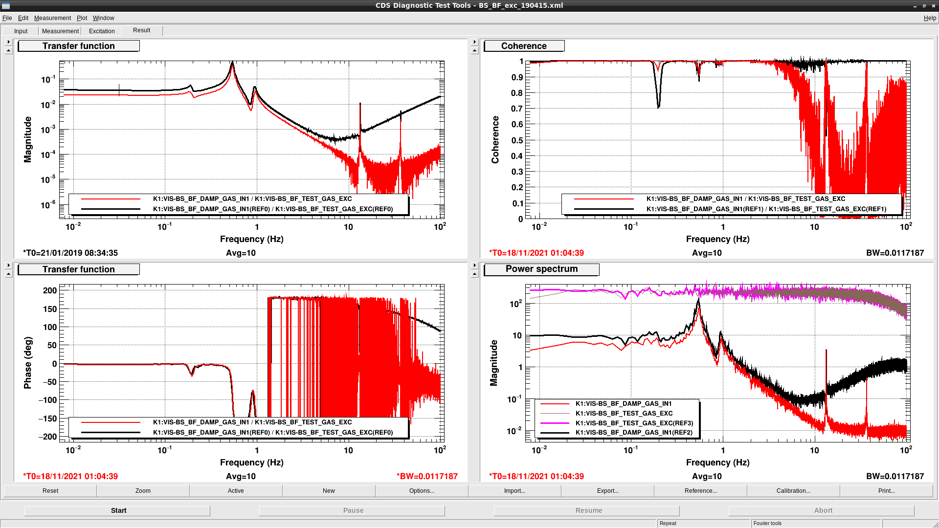
Bottom  Filter

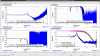
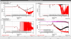
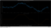
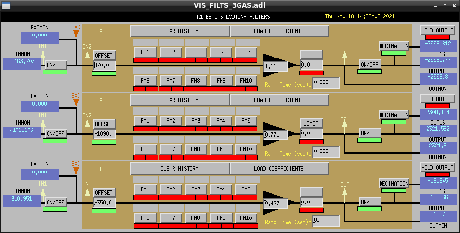
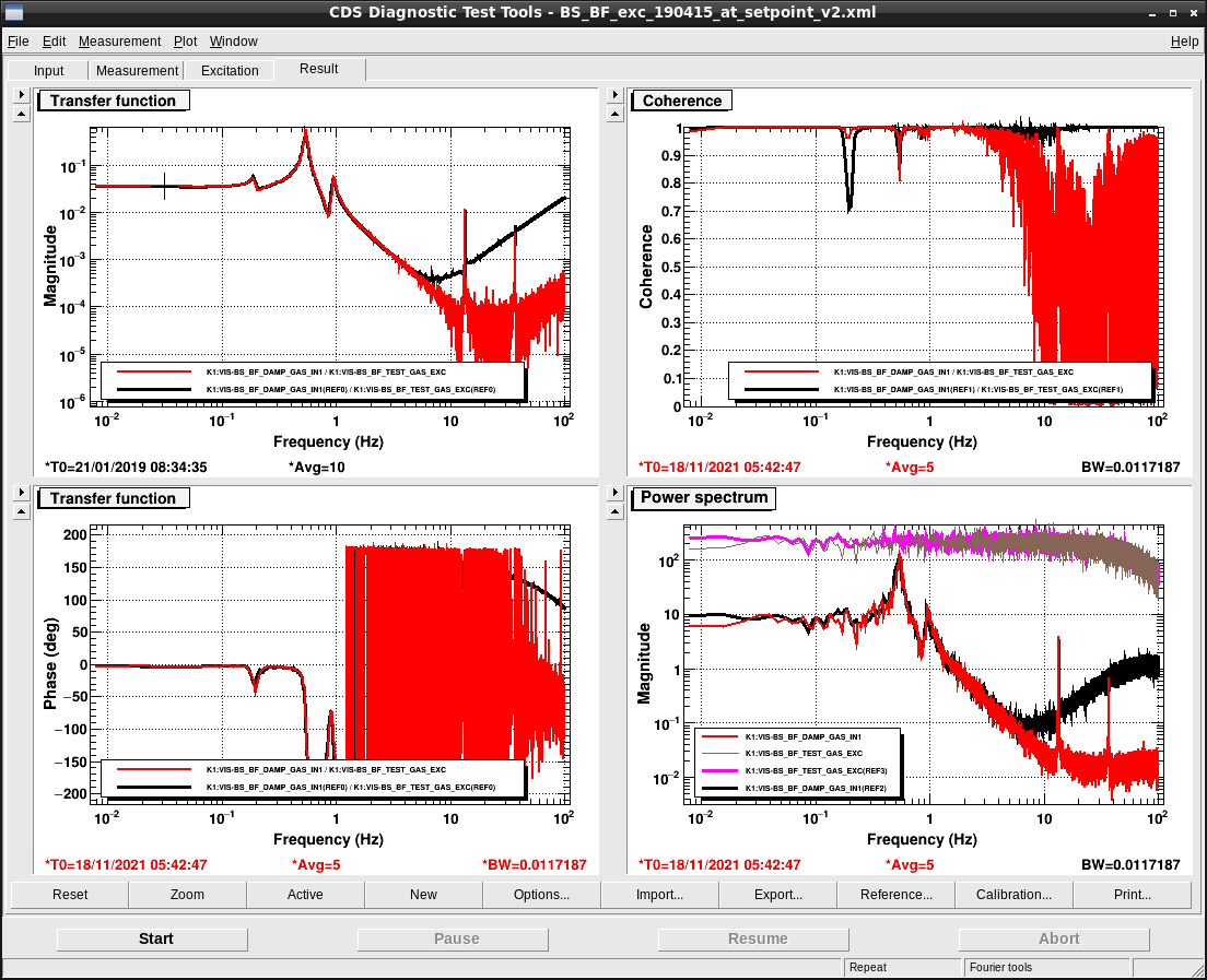
The position  of  the  keystone  given  by the  LVDT  is  close  to  what I  was  expecting.  Before  the  replacement  of  the  card  it  was  -186  um  and  after the  replacement  it was -179  um,  as  shown  in  the  first  screeshot.  The  second  screenshot shows  the  transfer  function.  Given the  logaritimic  scale,  the  amplitude seems  very  similar  to  what  it  was  before,  namely,  (  reference  /  measurement ) = [ 0.0358 (um/cnt) /  0.0228 (um/cnt) ]  =  1.570  (below  the  lowest  resonance  frequency).

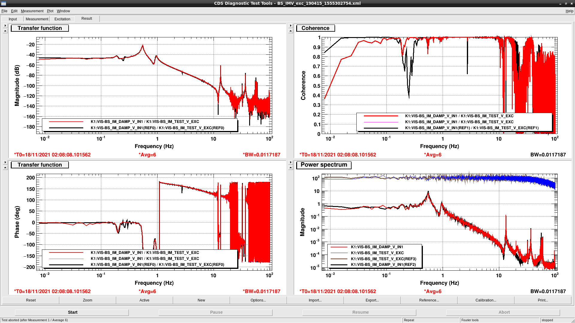
Then  I moved the keystone close to its setpoint, checked the vertical OSEMs  were  within  range ( IM-V  =  136  um)  and  measured  the  IM-V  transfer  function. The  result  was what  I  was  expecting.  See  the  third  screenshot.
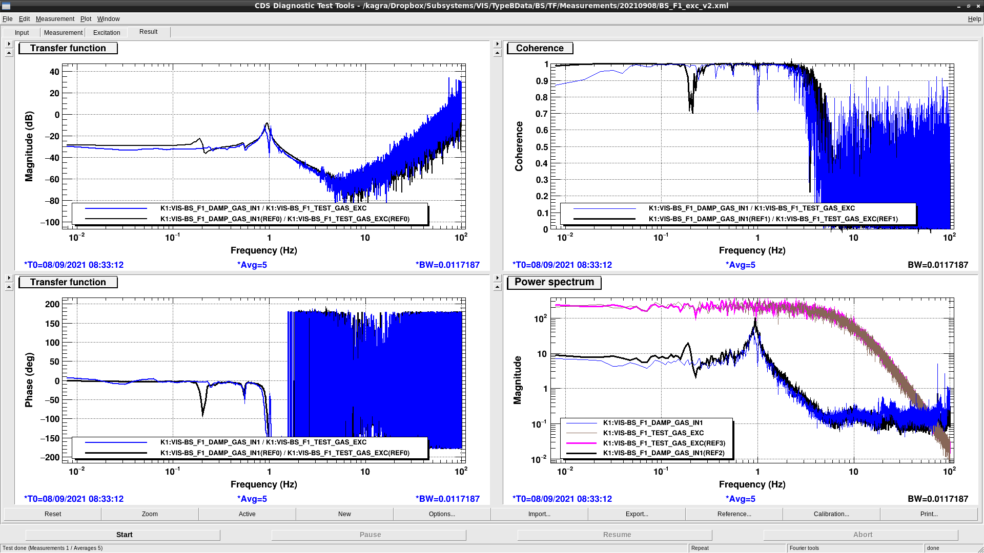
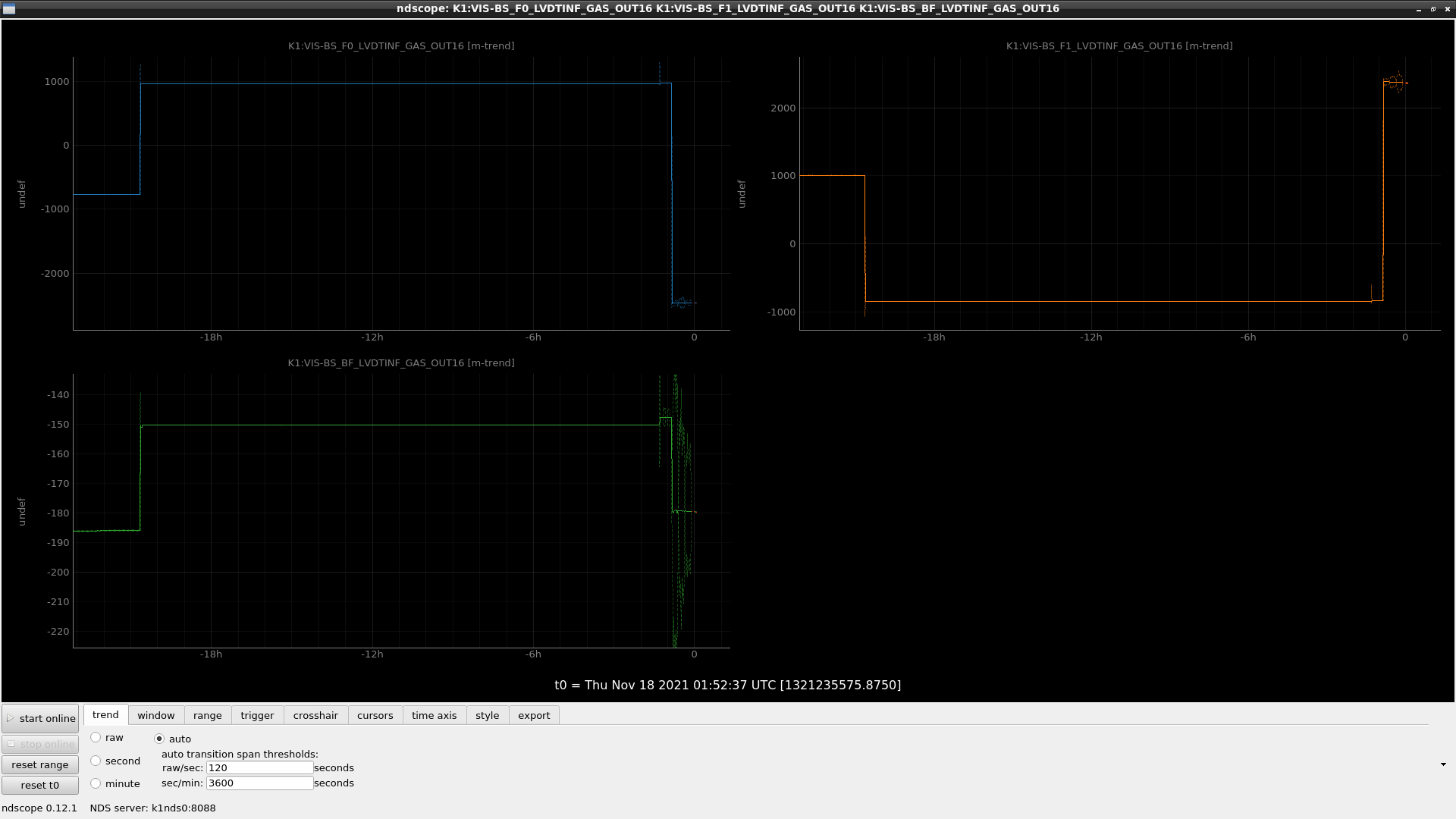
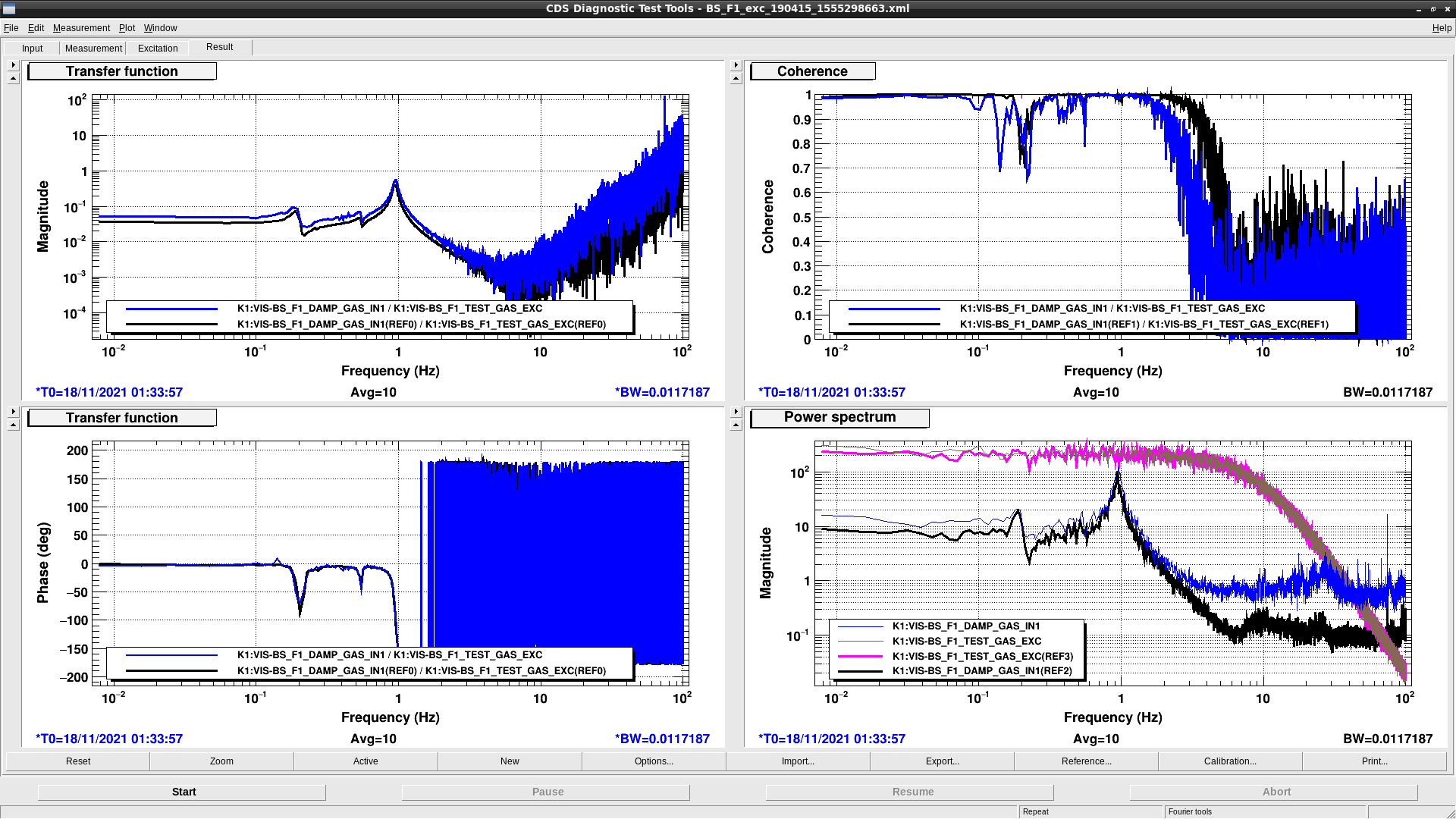
Standard  Filter  F1

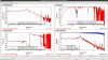
The  position  of  the keystone  given  by  the LVDT  changed  a  lot with  respect  to  what  it  was  before.  It  went  from  1007  um  to  2387  um  (first  screenshot  also).  The transfer  function,  in the  fouth  screenshot,  looks fine,  although  larger than the  reference.  We  should check  the  last transfer  function  measured  before  the  LVDT  began  having  problems  to  compare  to the  current  one,  but  for  now  let's  use  the  reference:   (  reference  /  measurement ) = [ 0.0340 (um/cnt) /  0.0490 (um/cnt) ]  =  0.710 .
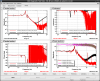
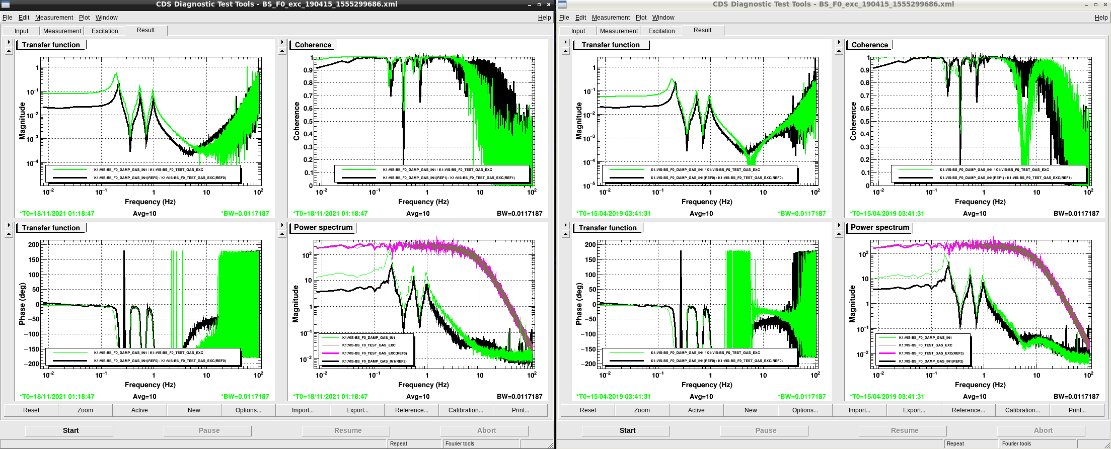
Top  Filter  F0

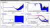
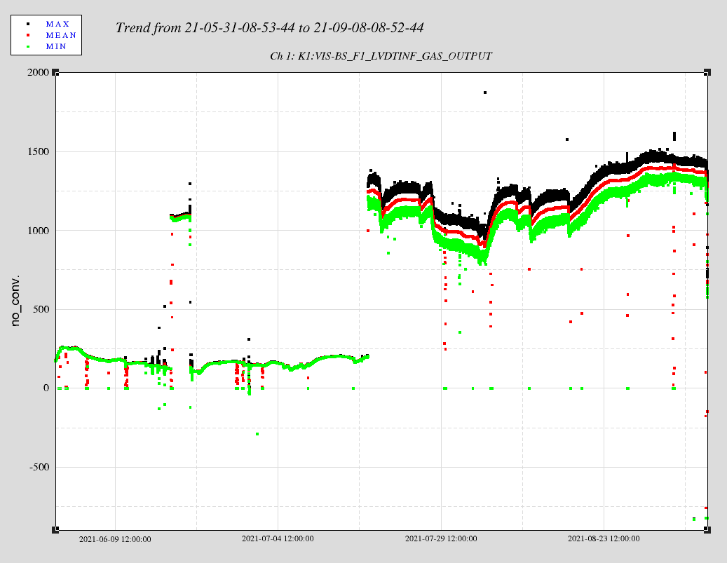
As  in t he  case  of  F1,  the  position  of  the keystone  given  by  the LVDT  changed  a  lot with  respect  to  what  it  was  before.  It  went  from  -764 um  to -2479  um  (first  screenshot  also).  The transfer  function,  on  the left-hand  side  of  the  fifth  screenshot,  looks fine.  The  amplitude is  larger than  the  reference,  nevetheless,  a  previous  transfer  function,  measured  on  the  15th  of  April  2019  and  shown  on  the  right-hand  side,  also  shows  a  larger  amplitude than  the  reference.  I'll use  this  measurement  for  comparison  instead  of  the  reference:  (  ref_april2019  /  measurement ) = [ 0.0585 (um/cnt) /  0.0775 (um/cnt) ]  =  0.754 .

Comments

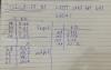
Although  the  transfer  functions  are  fine  in  terms  of  shape,  it  seems  that the  calibration  factors  (in  units  of  um/count)  and  offsets (in  units  of  counts)   need  additional  adjustment.  In  principle,  because  we  adjusted  the  resistances  in the  LVDT  card,  this  should  not be  necessary.  However,  practice  says  otherwise. We might  have  made  a  mistake in  adjusting  the  resistances.  Another  element  to  consider  that the  the  new  boards  are  slightly  different  and  I  don't  know  whether  this  would  affect the gains  and  phases  that  determine  the  offset  and  calibration  factor.

Images attached to this comment
fabian.arellano - 16:32 Thursday 18 November 2021 (18937) Print this report

Summary:  I used  the  transfer function  of the  Bottom  Filter  to  adjust the  calibration factor  (in units  of um/cnt)  and  the  offset  (in units  of  cnt).  I  didn't  do  it  for  F1  and  F0  becuase  F1  is  currently faulty  and  I  didn't  get  a  satisfactory  result for  F0.  Fortunately,  we  can  calibrate the F0 LVDT easily  because  we  have  access  to  it.

Let's  use  the  following  convention:

  • m:  old calibration factor  [um/cnt] 
  • m': new  calibration factor  [um/cnt]
  •  y0:  old  offset  [cnt]
  • y0':  new  offset  [cnt]

Then, the new calibration factor is  m' =  k * m,  where  k  is  the  ratio  of  TFs  reported  in  klog  18933. For  example,  for  the  BF,  F1  and  F0 ,  k is 1.570,  0.770  and  0.754  respectively.  The new offset  is  y0'  =  ( m / m'  )  *  y0 .  The  values  of  the  initial  calibration  factors  m  and  offsets  y0  are  shown  in  the  first  screenshot.  

With  this  information  I  calculated  m'  and  y0'  for  the  BF:

  • m'  =  0.670  um/cnt
  • y0'  =  -223  cnt.

This  new  offset  value favors  the  vertical  OSEMs.  When  the  BF is  at the  setpoint,  IM-V  is  at  approximately  100  um whereas  with  the  previous  offset  it  was at  about  160  um.  See  the  screenshot  of  the  TF.   I  also  accepted  the  new  values  in  the  SDF.

I  followed a  similar procedure  for F0,  but  the  new  offset  yielded  the  keystone  unexpecteadly far  away  from  the  setpoint  and  it  required  23,500  cnt  of  actuation to  reach  zero.  Likely,  I'm  using  a  transfer function  which  is  not  convenient  as  a  reference.  I  think  it's  better  to  calibrate  the  LVDT  again.  I  reverted  to the  original  values  using  the  SDF.

Images attached to this comment
fabian.arellano - 15:13 Friday 19 November 2021 (18953) Print this report

With Aso-san and Terrence.

Summary: we began testing a possibe way of improving the situation of the LVDT in the F1 GAS filter. The problem with the LVDT is that the secondary coil has a stray connection to ground (18264). We still don't have conclusions and investigation will continue next week.

Today we tested an electronic circuit adapter that does the following:

  • It routes the reference signal to the secondary coil rather than to the primary coil and uses the primary coil as readout. This seems to work in SRM IP LVDTs, in which there was an error in putting the pins in their nominal places in the connector, so we want to test this scheme for this LVDT.
  • It converts the output, with the reference signal for the LVDT, from a double-ended output to a single-ended output. This enable us to cope with the stray connection to ground.

One of the symptoms of the problem is that the LVDT signal is noisier than when the stray connection to ground appeared. This means that we should aim to characterize the noise reduction in order to judge whether this strategy works or not. We didn't have much time to do measurements, but we did notice that the new electronics changes the overall amplitude of the signal, including the noise.

We will continue the investigation next week.

fabian.arellano - 17:05 Thursday 02 December 2021 (19059) Print this report

With Hirata-san.

We changed some of the old flip adapters for new ones. We only did two flanges today. A spreadsheet with data is attached.

Non-image files attached to this comment
naoatsu.hirata - 13:58 Friday 03 December 2021 (19073) Print this report

With Yasui-san,


We finished changing flip cables for BS. 

We checked cable connection. A spreadsheet with data is attached.

Non-image files attached to this comment
fabian.arellano - 15:46 Tuesday 07 December 2021 (19104) Print this report

With Terrence.

Summary: we corroborated that the new adapter circuit for the F1 LVDT (entry 18964) changes the polarity of the readout. We should change the polarity of the primary coil within the adapter box in order to fix this.

Terrence reported recently that the polarity of the actuation-LVDT-readout system was apposite to what we had before, so I checked.

First I corroborated that negative actuation produced positive readout from the LVDT. This is not what we want. Then I removed the adapter circuit  (entry 18964) and corroborated that the correct polarity was recovered.

We would like to set the polarity in hardware, not in software. The appropriate way of doing it would be to exchange the places of pins 2 and 7 inside of the adapter circuit box. Pins 2 and 7 connect to the LVDT primary coil, which is healthy and is used as a readout with the adapter circuit.

fabian.arellano - 17:14 Thursday 06 January 2022 (19373) Print this report

With Hirata-san.

In the adapter circuit for the F1 LVDT, We exchanged the places of the cables connected to pins 2 and 7 in order to recover the corect polarity of the F1 LVDT. We made the change at the connector that receives the cable from the vacuum chamber. See pictures.Then we tested the connection with a multimeter.

We didn't have a solder remover at the tunnel, so we brought the box to the office and made the soldering here. We'll install the box tomorrow. The F1 LVDT is disconnected now.

We will test the circuit tomorrow.

Images attached to this comment
fabian.arellano - 17:11 Friday 07 January 2022 (19395) Print this report

We connected the adapter to the F1 LVDT again. However, we were not able to test the change because DGS maintenance was happening at the time.

fabian.arellano - 14:48 Wednesday 19 January 2022 (19506) Print this report

I tested the polarity of the LVDT. On the 6th of January, we changed the polarity, but we had not tested it provides the expected output.

According to the test, the polarity now is correct: positive actuation, which we know moves the keystone upwards, produces a positive LVDT readout.

Images attached to this comment
Search Help
×

Warning

×