YamaT, Akutsu, + Miyoki; related to 18005 and 18002. Similar to 14569.
Abstract
Estimated the cavity-pole frequency of IMC by measuring a transfer function in the control loop; 6.159 (+/-0.185) kHz. Assuming the absolute round-trip length 53.3 m, this corresponds to finesse 457, which would be consistent with the designed value 460, and measuerment by K. Tanaka in 18005.
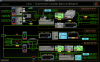
Setup of the measurement
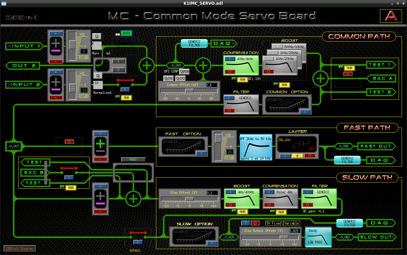
Referring the past measurement reported in 14569, we connected the common mode servo (CMS) and the Agilent 35670A (FFT signal analyzer) with cables as follows:
- CMS's Input Section's OUT2 --> FFT ch2; note that there has been a 20 dB attenator before IN1 (maybe the same situation as in 14569... maybe), and the gain between IN1 and this OUT2 was 4 dB.
- CMS's Slow OUT1 --> divided by a T --> FFT ch1, while connecting the output to the NPRO PZT.
- FFT excitation --> CMS's Excitation A EXC.
Firstly we tried to measure those things just with keeping the EOM path, but later eventually, referring 14569, we disconnected the EOM path for our measurement. Moreover, although the following changes would not directly affect the result of our measurement, I want to slightly summarize thinngs for clarity; because we learned that the IMC lock could not be stable when leaving some "boost" filters in the CMS turned on automatically by Guardian, we determined our mind to tentatively chang the Guardian code not to turn on them automatically, and tried each one by one to find a stable combination of the boost filters; eventually we determined our mind to just turn on a 4Hz-400Hz boost filter in the slow path for our measurement (of course, later, we got back the EOM path and the Guardian code, seeming hopefully).
Measurement and post analysis
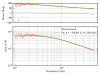
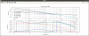
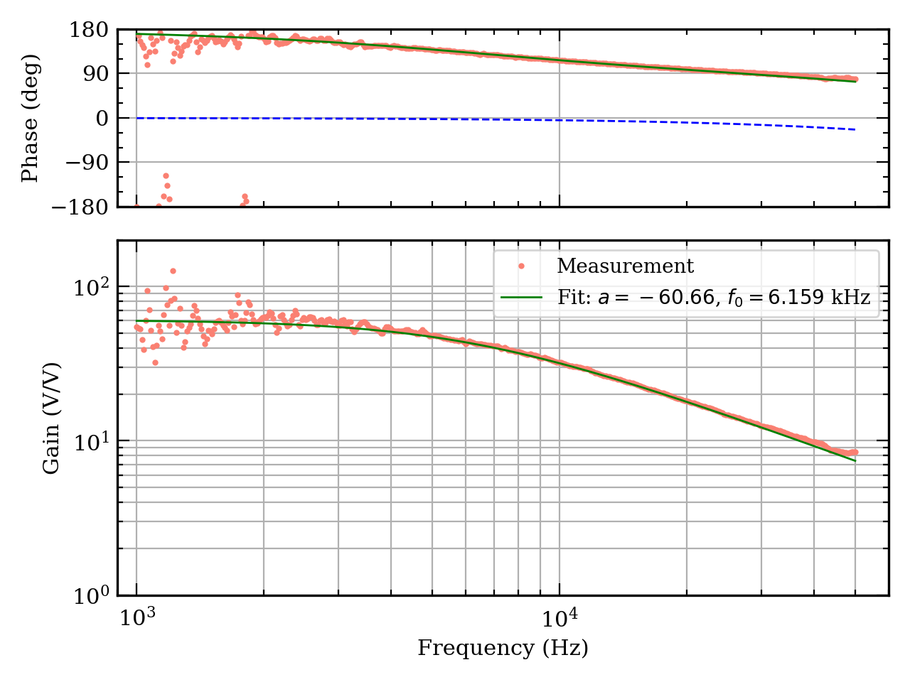
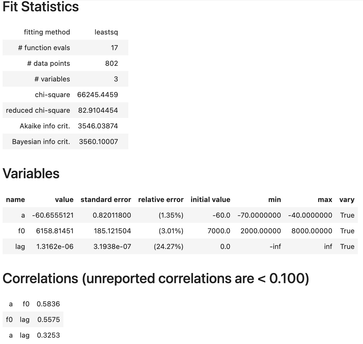
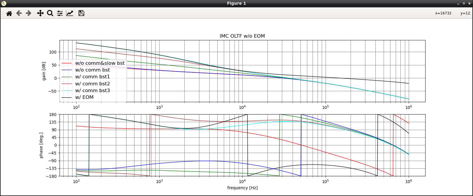
We tried several amplitude about the excitation signal injected to the CMS from FFT; 50mVpk - 500mVpk. With 500mVpk, IMC was immediately down. With 300 mVpk, the IMC transmission power seemed lowered, that would mean the lock became unstable and the transmitting power fluctuated. So 100-200 mVpk was better or best. 50mVpk was a little nit noisy (lower coherence). Trying some combinations of the settle cycles ~ 10 cycles, integration cycles ~ 50 cycles, and number of measured frequency points... then we obtained the resultant transfer function around the cavity pole frequency (Fig. 1), and Fig. 2 is a table of the fitting. The fitting says:
- DC gain: 60.66 +/- 0.82
- Cavity pole: 6.159 kHz +/- 185.1 Hz
We also included a time-lag exp(-2*pi*j*f*lag) into the usual single pole function for fit, for some reason (maybe just following 14569, sorry), which is shown in a blue curve in the phase pane.
A cavity's finesse F = 2*pi*t0 * c/L, where L is the absolute round-trip length, and t0 is the strage time, where t0 = 1/(4*pi*f0), so F = c/(2*L*f0) = FSR/(2*f0). Assuming L = 53.3 m, then finesse can be estimated as 456.6, which would be consistent with the design value 460, and also those obtained by K. Tanaka 18005.
Mistery
Comparing the DC gain reported in 14569, which is 2.69, our DC gain is totally different. One difference may the 4dB gain between IN1 and OUT2, but considering this only helps literally 4dB. Well... we need to check IN1-OUT2 again...
Tips
- The data and the script for analysis are located at
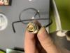
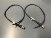
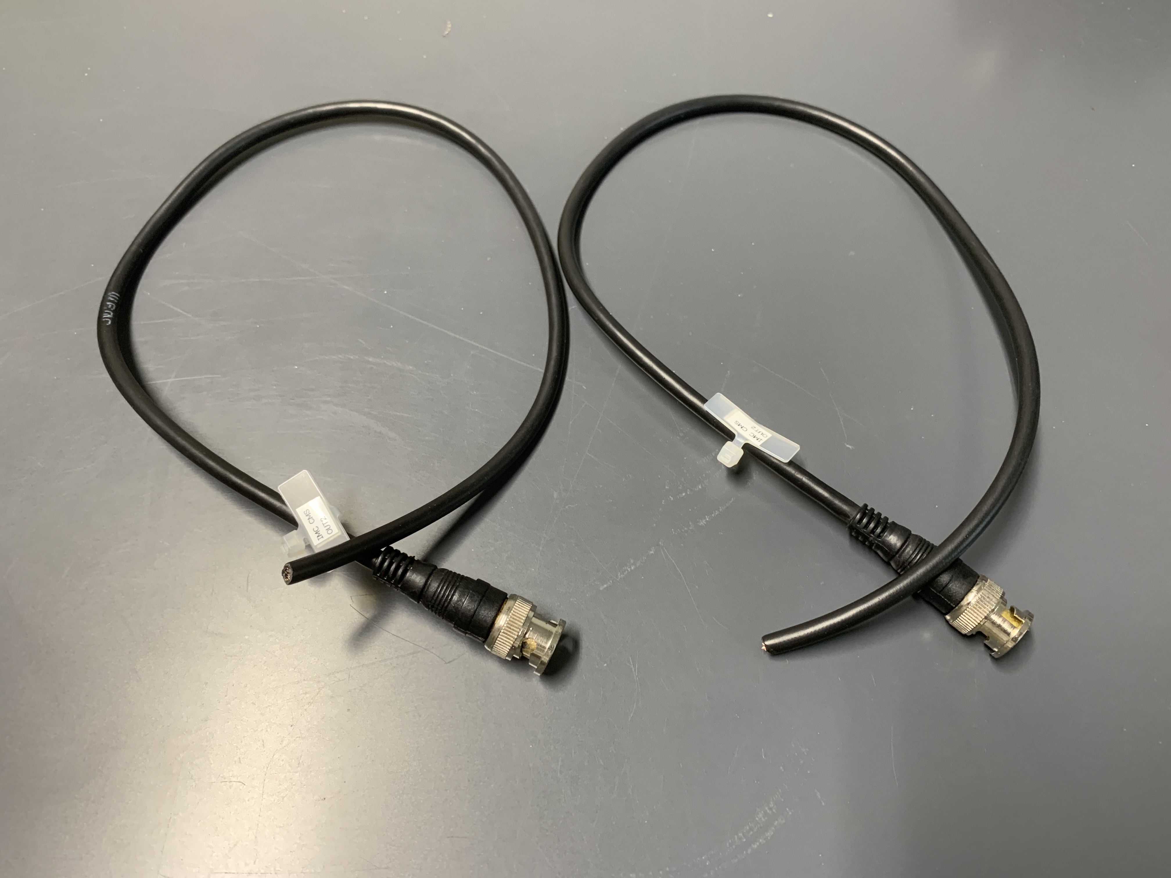
/users/Commissioning/IMC/data/CavityPole/20210825/ - We were firstly suffered from bad S/N of our measurement, and my sixth sense told me that this was due to one of cables connecting the CMS and 35670A. Replacing it with a new cable, 35670A stopped to show continous overload rejection, and our measurement S/N was drastically improved. According to Miyoki-san, the cable's two connetctor-shrouds would be floating (?) with each other, but I'm not sure well. What I found was just that the cable's metal parts seemed strange color (yellowish? golden??) to me...
