Reports 1-1 of 1 Clear search Modify search
VIS (IX)
masahide.tamaki - 16:37 Friday 30 July 2021 (17699) Print this report
sensor balancing

[Ushiba, Tamaki]

Abstract

We did sensor balancing of MN and IM for ITMX using transfer function. 
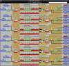
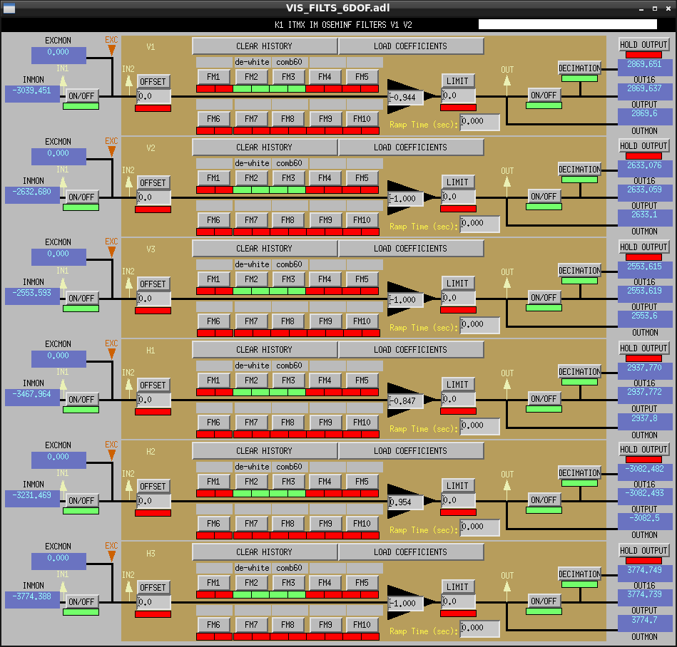
Then we put the gain into K1:VIS-ITMX_{MN,IM}_OSEMINF_{H1,H2,H3,V1,V3}_OUTPUT like Fig1 and 2.

Detailed

We have diagonalized OpLev last week, so we became to be able to monitor DOF independently. And we balanced actuator (klog 17672 and 17683) in this week.
However, the sensitivity of sensor had be disparate yet so we did sensor balancing of MN and IM for ITMX by adjusting the gain.

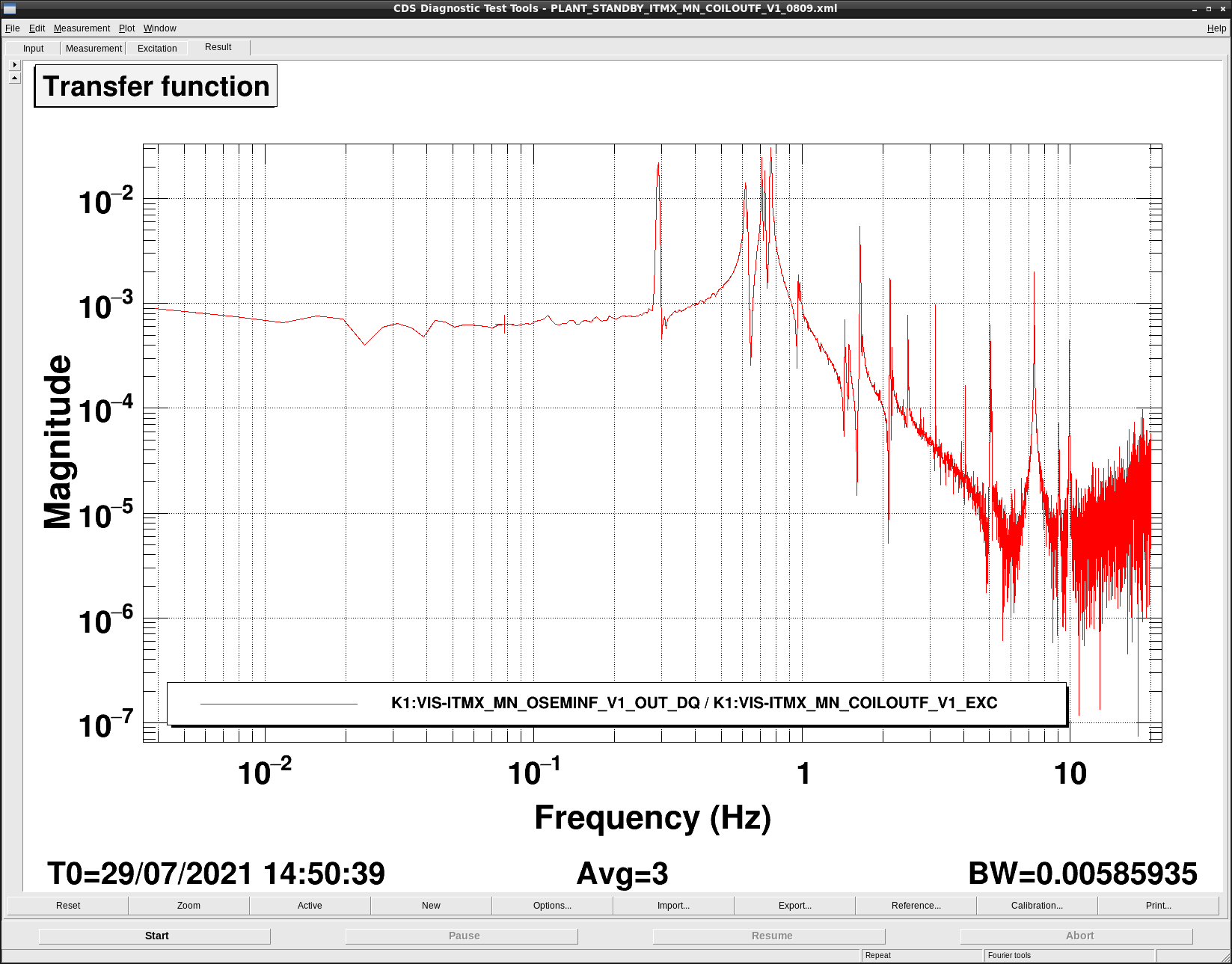
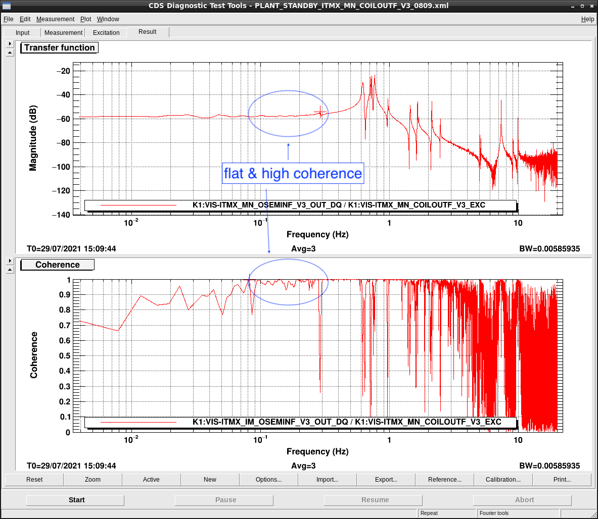
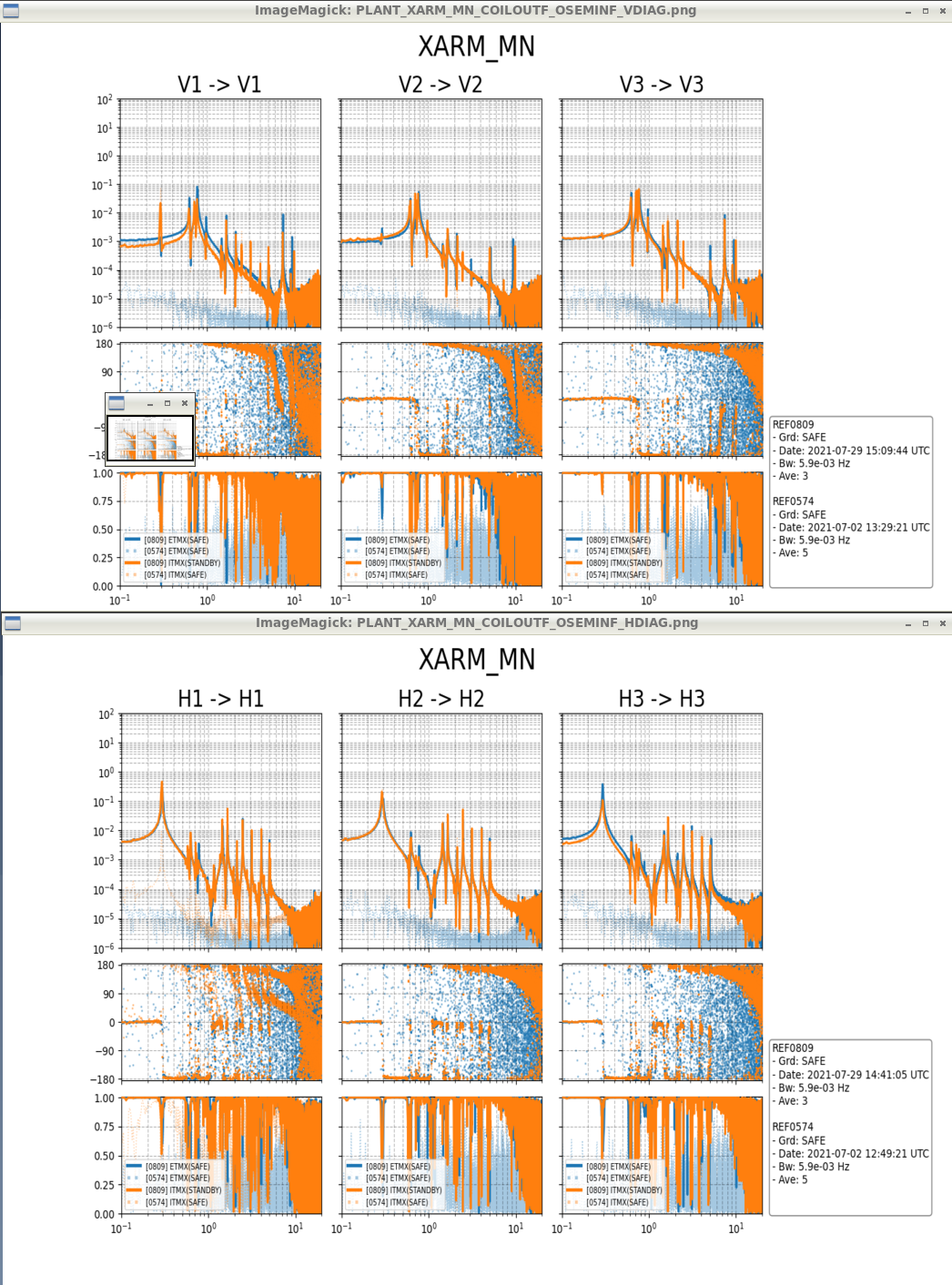
We used the transfer function (K1:VIS-ITMX_{MN,IM}_OSEMINF_{H1,H2,H3,V1,V3}_OUT_DQ / K1:VIS-ITMX_MN_ COILOTF_{H1,H2,H3,V1,V3}_EXC).
(We didn't measure V2 because we didn't balance actuator (there is no sensor))
The pictures of these transfer functions are in /kagra/Dropbox/Measurements/VIS/figures (File name is PLANT_XARM_MN_COILOUTF_OSEMINF_{H,V}DIAG.png).
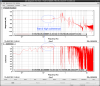
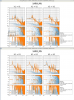
We took the average of five points in flat and high coherence area (like Fig 4), and decided the gain as follows (Fig 1,2).

MN
V1: -1.000
V3: -0.512
H1: -0.822
H2: -0.745
H3: -1.000

IM
V1: -0.944
V3: -1.000
H1: -0.847
H2: -0.954
H3: -1.000 

We didn't put the gain of MN V1, V3 because there was the suspicios point in transfer function of V1. 
・Although we didn't actuate, the signal can be seen (Fig3). 
・There is the signal of rotation direction despite this sensor monitors vertical direction. (On the other hand, there is no peak in the transfer function of V3 (Fig4).)
As mentioned above, the gain ratio of V1 to V3 calucurated was 2:1.
This may be caused because one side of these sensors is out of order.

Images attached to this report
Comments to this report:
takafumi.ushiba - 13:57 Saturday 31 July 2021 (17711) Print this report

Thanks to Miyo-kun, transfer functions of ITMX and ETMX were measred in last night and I checked them.
Attached figure is the transfer functions from each coil of MN stage to each photosensor at the same stage.
Accroding to this result, DC gains of ITMX H3 and V1 are slightly smaller than those of ETMX's.
So, one possibility of strange behaviour of V1, which has been already reported on this original post, is some coupling betwee MNH3 and MNV1.

I will check theses sensors and actuators in the next week first.

Images attached to this comment
takafumi.ushiba - 17:19 Saturday 07 August 2021 (17842) Print this report

Abstract:
I repeated actuator balancing of MN stage without OpLev diagonalization matrix and confirmed that OpLev seems to be used for actuator balancing without diagonalization.
After the measurement, I set measured values in this time to COILOUTF gains and accepted SDF in both SAFE and ALIGNED state. 

Details:
I repeated actuator balancing with the same method in klog17683.
Difference of the measurement is followings:
1. OpLev calibration factor wasn't changed in this time.
2. OpLev diagonalization matrix wasn't used.
3. Excitation signal was two times larger than previous measurements (1000 counts for PIT, 200 counts for YAW).

As a result, I obtained following actuator balancing gains for MN actuators (I also put the previous result in the bracket).
H1: 1.00 (1.00)
H2: -0.865 (-0.871)
H3: -0.942 (-0.942)
V1: 0.950 (0.950)
V3: -1.00 (-1.00)

H2 values are different from the previous results but the difference is less than 1% and enough small for the actuator balancing.
So, it doesn't seem to be necessary to diagonalize OpLevs for actuator balancing.

Measurement data is stored at /users/VISsvn/TypeApayload/ITMX/Spectra/20210807/.

takafumi.ushiba - 18:50 Saturday 07 August 2021 (17847) Print this report

Abstract:
I performed photosensor balancing for ITMX MN stage and set the gains in OSEMINF filter bank.
After changing the gains, I accepted SDF in both SAFE and ALIGNED state.

Details:
I injected excitation signals (0.1-Hz sine signals) to each coils from EXC port in COILOUTF at ITMX MN stage.
The values of excitation signals are 1000 counts for V1 and V3, and 200 counts for H1, H2, and H3.

While injecting the signals, I measured the spectra of MN_OSEMINF_OUT_DQ and compaired the height of the peak.
During the measurement, the gains of MN_OSEMINF filter banks are as follows:
H1: -0.82165
H2: -0.7449
H3:-1
V1:-1
V2:-1
V3:-1

From above initial gains and measurement results, I obtained following new gains for each sensors.

H1: -0.856
H2: -0.732
H3:-1
V1:-1
V2:-1
V3:-0.513

Measured data were stored at users/VISsvn/TypeApayload/ITMX/Spectra/20210807/.
After the measurement, I set the new gains and save SDF in SAFE and ALIGNED state.

Search Help
×

Warning

×