I was trying to align the geophones to the LVDTs using the ACC2EUL matrix. I do so by first aligning the actuators to the LVDT L/T/Y at 0.2 Hz. This way I know the actuators can actuate in pure L, T, and Y at 0.2 Hz. Then, I can inject 0.2 Hz and align the geophones.
However, there was strange phase response from the geophone T readout. This reminds me of the strange phase response at 1 Hz when I was inter-calibrating the geophones to the LVDTs.
This inter-calibration was done exciting yaw motion and comparing the yaw readout from the LVDT to the geophone displacement readout. The ratio between the yaw readout and the geophone readout should equal the inverse distance from the centre of the IP table to the geophone, which is 1/0.5915 ~ 1.69 (1/meter).
Since the yaw signal is dominated at the resonance, which is around 0.3 Hz, I used the readouts at this frequency to adjust the gain of each geophone readout. The ratio between the yaw readout and the geophone readout should be flat with zero phase. But this was not true at around/after 1 Hz.
I believe this was due to wrong calibration filters so I can't help but revisit them.
The geophone calibration filter parameters were given by Fujii two years ago here.
It turned out the calibration filters used for H2 and H3 was just a copy of that of H1 and is not the same given by Fujii.
I modified the calibration filters according to Fujii's calibration and adjusted the gain accordingly.
The ratio between yaw and H3 got flat but H2 is still bad. So I derived the correct frequency and damping factor of the calibration filter from the measurement I got. This can easily be done but I won't discuss details here.
The resonance frequency f0 and damping factor eta were found to be 0.9745 Hz and 0.3731 respectively.
I modified the calibration filters and remeasured the yaw-geophone ratios and they got much flatter.
Fig. 1 shows the yaw-geophone ratios. The references (brown, purple and cyan) were measured with old calibration filters, and yellow is just the yaw actuation to LVDT yaw transfer function for reference.
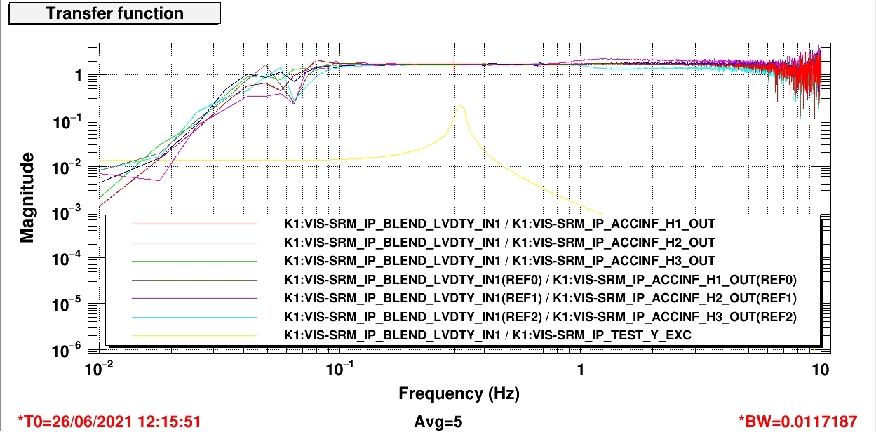