Tanioka, Akutsu
Abstract
We tried to relocate the POP-POM behind PR2 but found it was difficullt, as there were not enough useful references or drawings. Anyway, we will continue this tomorrow.
Preparations
- PR3 target: Hirata-san and Yano-san has set the target plate in front of PR3 in the morning (Will be reported by them).
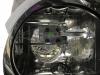
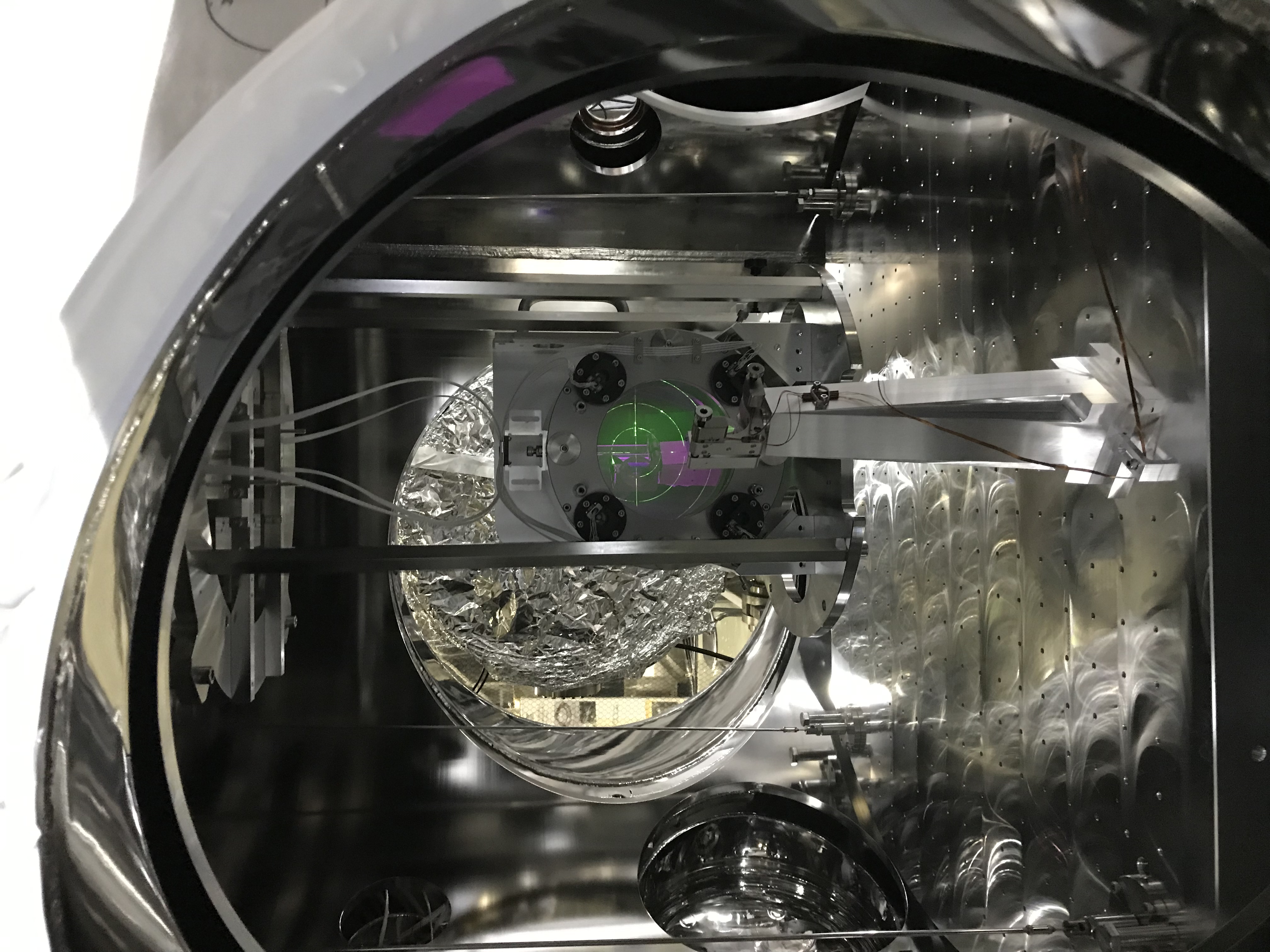
- PR2 target: had been already there as a remnant of the previous work. Anyway, we can see the target also from behind the PR2 (Fig. 1); thank you for the transparency of the mirror material...
- Released the PR2 optical table in the PR2 chamber.
- The green beam shutter is still on the POP table... should be moved to PSL room soon! Anyway, we opened it.
As a first look
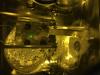
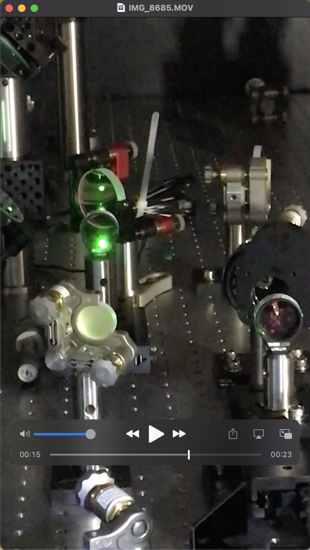
The green spot illuminating the PR2 target backside seemed clipped elsewhere and showed an interference pattern. Fig. 2 was taken through a laser safety goggle, otherwise due to saturation the beam spot would get smeared and such detailed intereference pattern could not be observed. Well, even with the photo like Fig. 2, it is difficult to see the interefence, but human eyeballs through the goggle could identify it. As seen in this photo, at this stage, the green beam spot (though clipped) was slightly shifted in upper right from the PR2 HR center. This was not bad starting...
Where is the clipping?
Firstly we found the green shining at the lower limit of a lens holder on the POP table (Fig. 2), and re-align around these, but finally Tanioka-kun noticed that the beam clipping might start at the Faraday isolator. While tweaking these, he found this activity affected the FNC and so on... sad. Will be reported by him in a separate post. He will work for recovering this at first tomorrow.
What should be the procedure?
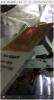
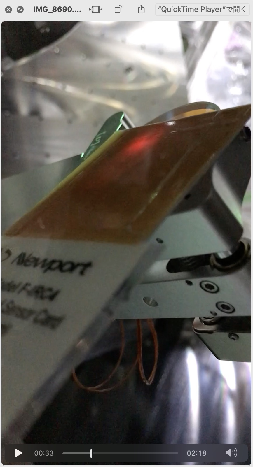
Anyway, we found the IR transmission from IMMT2 to PR2 was hitting on the POP-POM. The spot was slightly off-centered in -Y direction (Fig. 4), which would be along the design qualitatively in principle. But considering the situation, now I feel I need to considert the alignment procedure here very carefully. What we should do are
- Extract the PR2 transmission IR forward beam to the POP table to make a new optics path for monitoring the transmission beam axis (One of homeworks after O3GK)
- Input GreenX thorugh the centers of PR2-PR3.
Need to stop to consider well with ray-tracing...