Reports 1-1 of 1 Clear search Modify search
VIS (SR3)
fabian.arellano - 14:44 Monday 14 June 2021 (17105) Print this report
IP resonant frequency adjustment.

With Hirata-san.

As preparation for ballast mass adjustment, we measured the IP resonant frequencies:

  • IP-L: 93 mHz
  • IP-T: 78 mHz
  • IP-Y: 328 mHz
  • Frequency resolution: 10 mHz
  • The temperature was 23 °C, which is the O3GK temperature (klog 15816).
  • A previous measurement at 24 °C is reported in klog 15018.
Images attached to this report
Comments to this report:
fabian.arellano - 21:24 Monday 14 June 2021 (17111) Print this report

With Hirata-san.

Pictures at SR3 remedying work after O3.

We added ballast mass onto the IP:

  • 1339 g (3 mm X 120°)
  • 1355 g (3 mm X 120°)
  • 1109 g (one of the small ones)
  • 1100 g (one of the small ones)
  • Total: 4,903 g

We divided the new load in two sets and placed them on opposite sides of the IP. Then we measured TFs. The change in resonant frequencies in L and T are:

  • IP-L: 93 mHz ⇒ 78 mHz
  • IP-T: 78 mHz ⇒ 47 mHz
  • IP-Y: 328 mHz ⇒ not measured yet.

The IP-T frequency is too low and the IP may become unstable. In ordert to try to decrease the assymetry we moved all the ballast mass to one side (-X). We'll measure transfer fiunctions.

Images attached to this comment
fabian.arellano - 15:44 Tuesday 22 June 2021 (17207) Print this report

With Hirata-san.

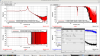
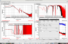
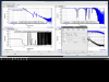
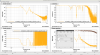
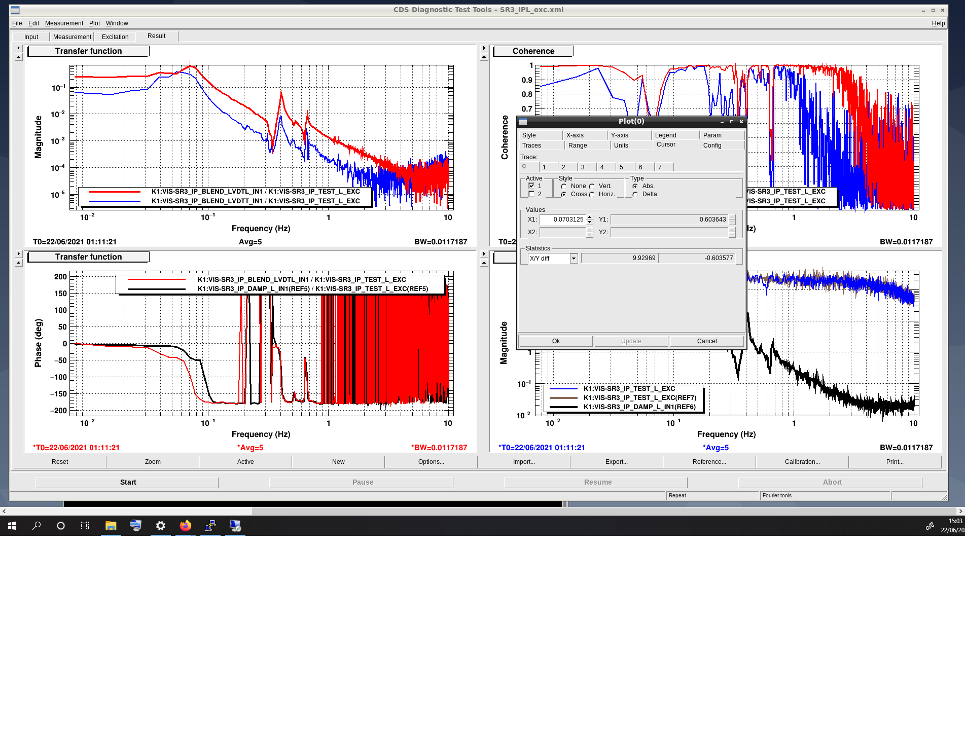
Previously, we measured that the IP resonant frrequencies in L and T were 78 and 47 mHz respectively. The lower one is too low and the IP may become unstable under such condition. Therefore, we decided to try decrease the asymmetry by moving some of the the ballast mass to the -X side. Today we measured the TFs after moving the IP close to the setpoint using the horizontal fishing rods.   The resonant frequencies were:

  • IP-L: 70 mHz
  • IP-T: 47 mHz
  • Difference: 23 mHz
  • Resolution: 10 mHz

The frequency in IP-L decreeased by 8 mHz, but in IP-T it remained too low at 47 mHz.

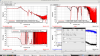
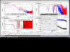
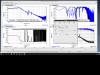
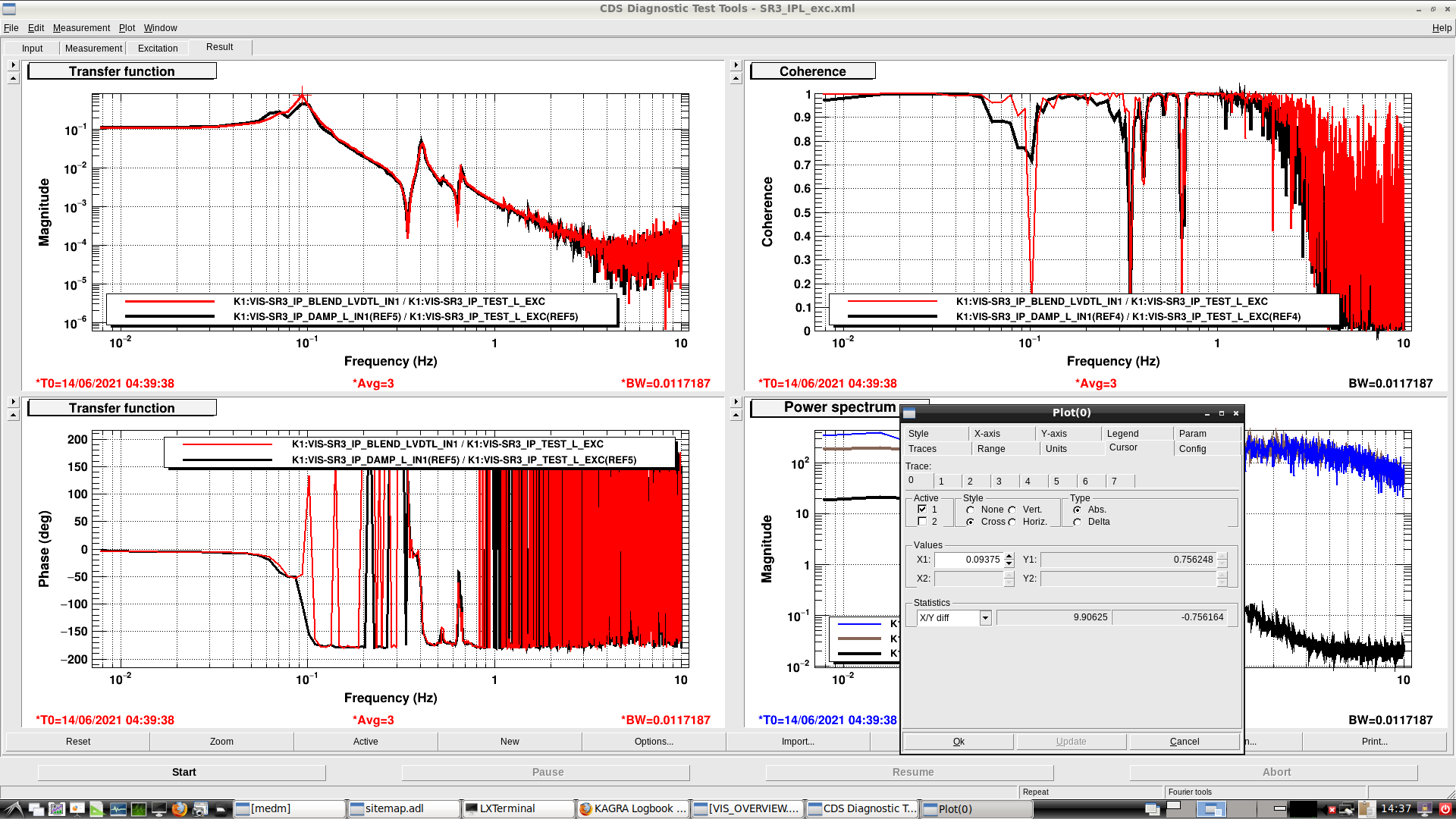
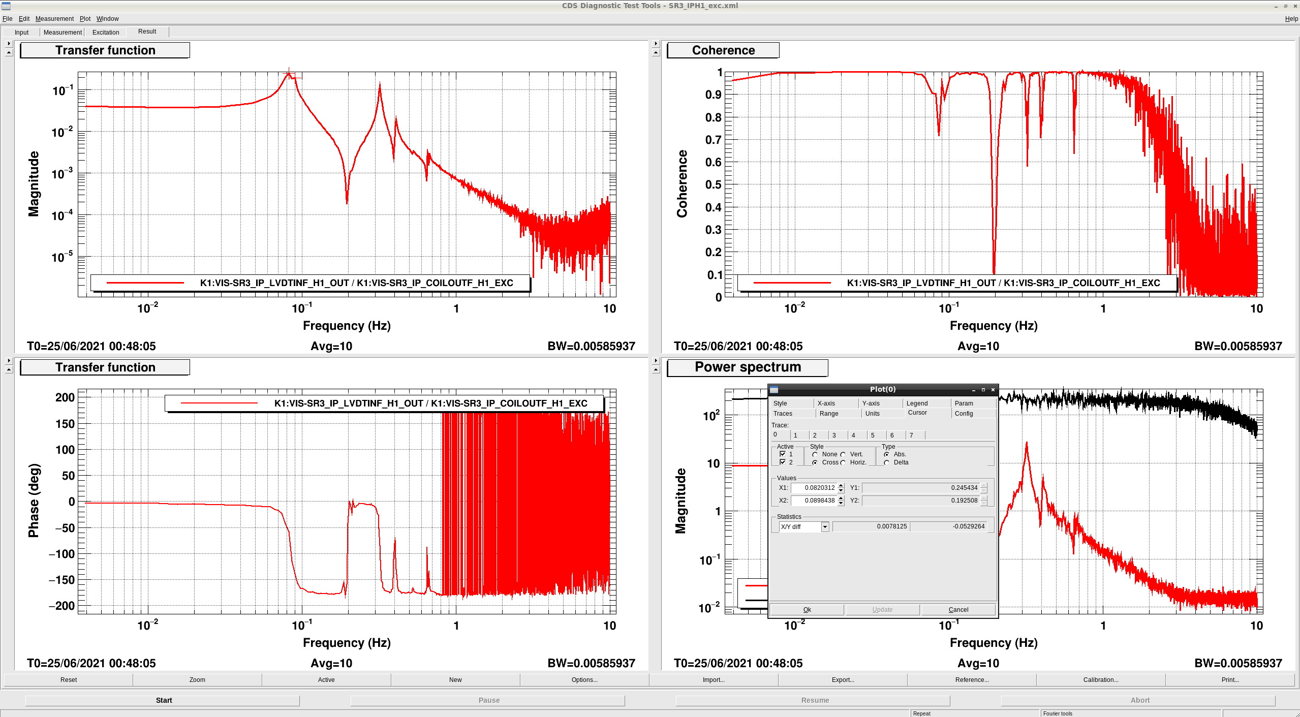
Then we removed 1109 g (1 ×10 mm × 30°) from the IP and moved the following masses to the +X side:

  • 1339 g (3 mm × 120°)
  • 1355 g (3 mm × 120°)
  • 1100 g (10 mm × 30°)
  • Total: 3,794 grams.

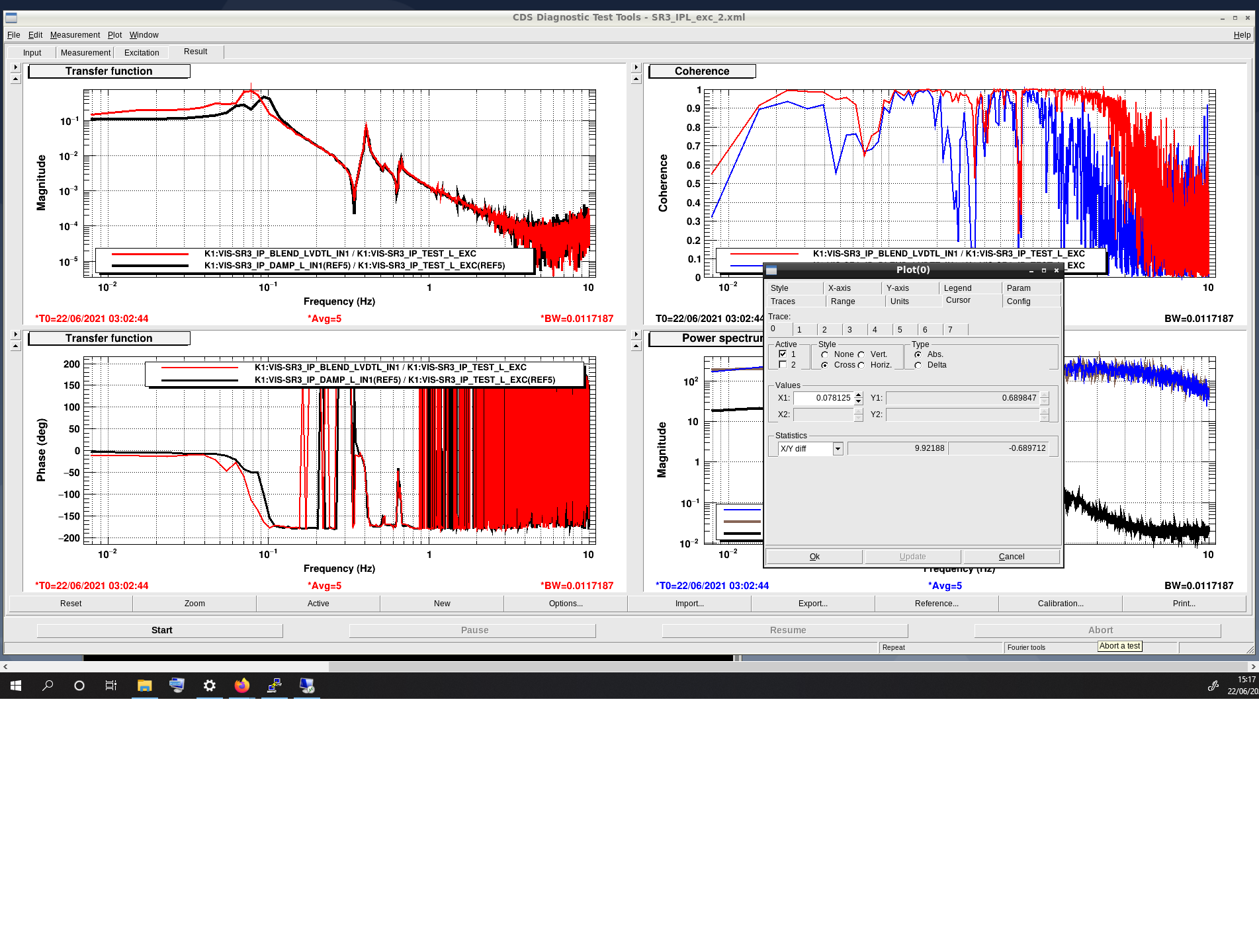
We measured TFs again with the following resonance frequencies:

  • IP-L: 78 mHz
  • IP-T: 55 mHz
  • Difference: 23 mHz
  • Resolution: 10 and 5 mHz
  • File: with _2

The vales are higher but the difference is still 23 mHz.

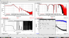
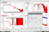
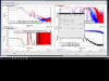
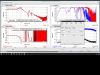
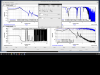
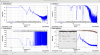
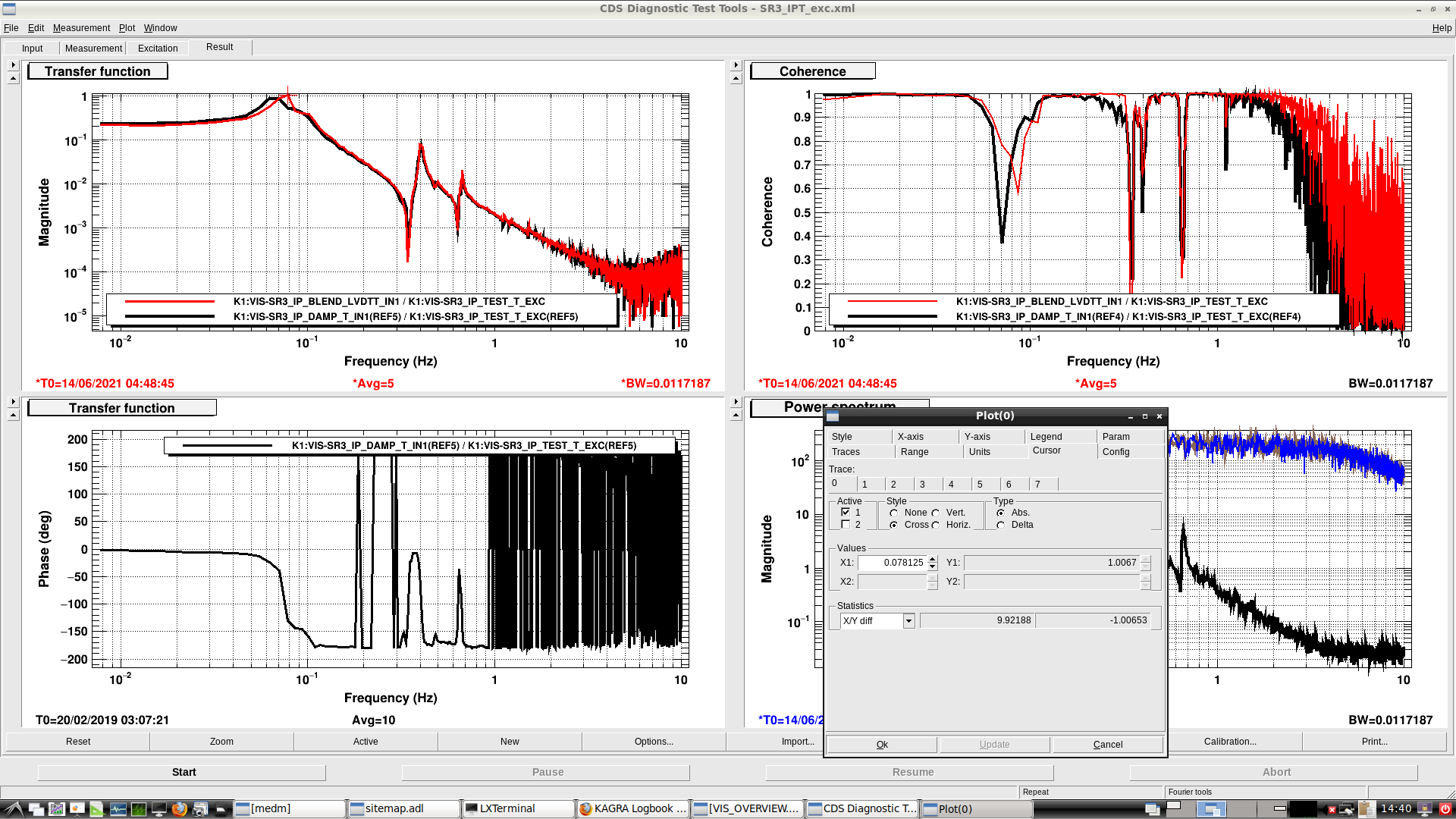
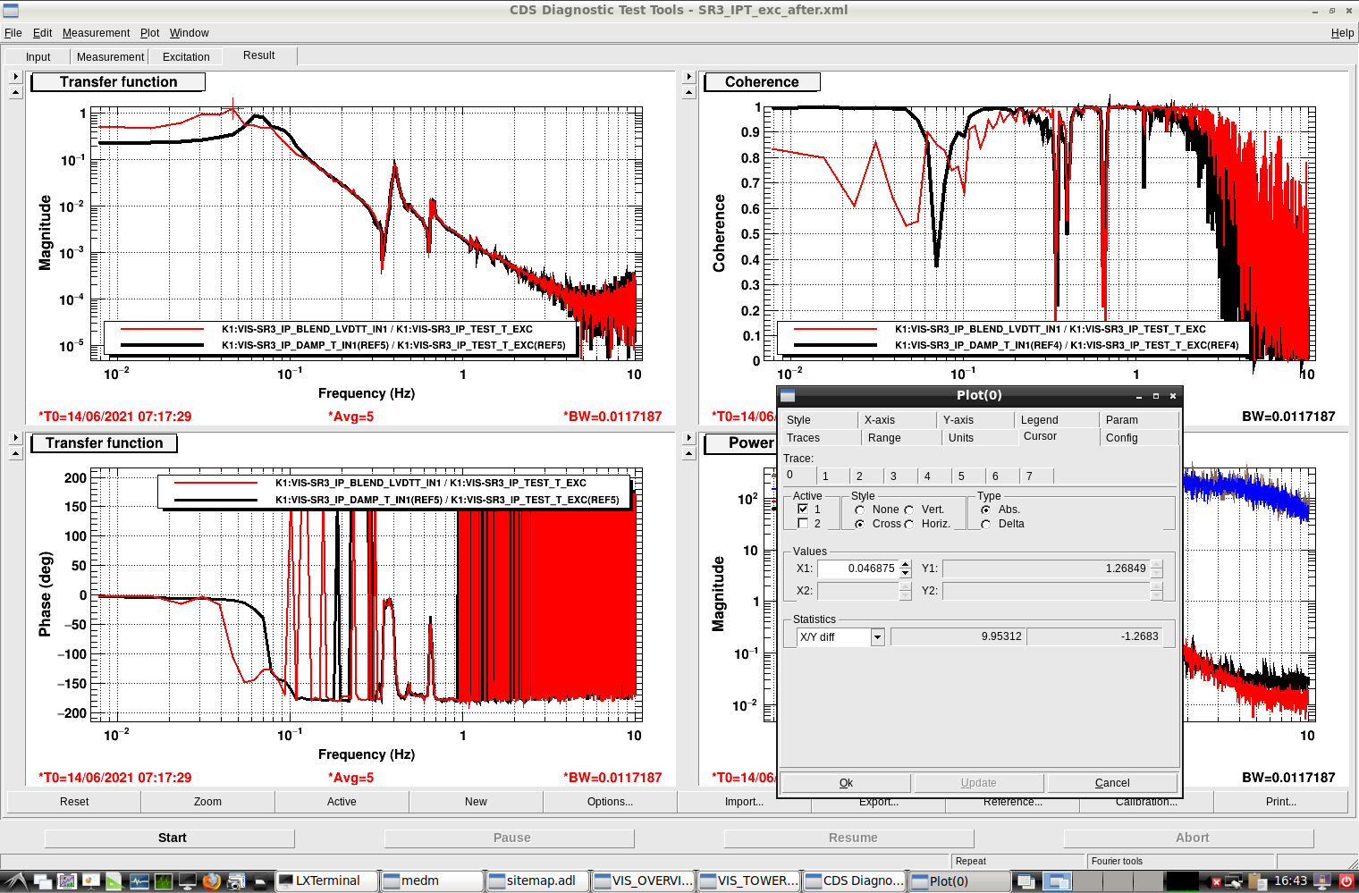
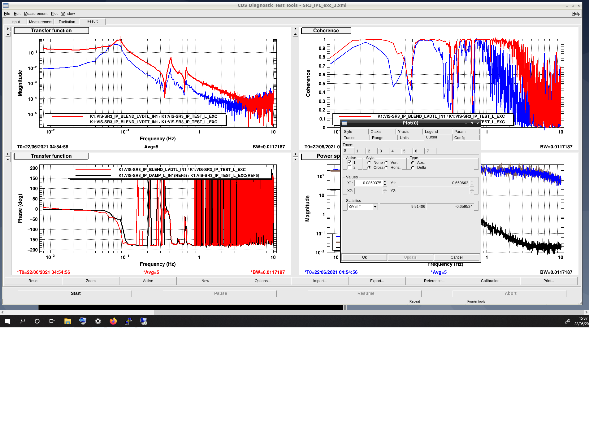
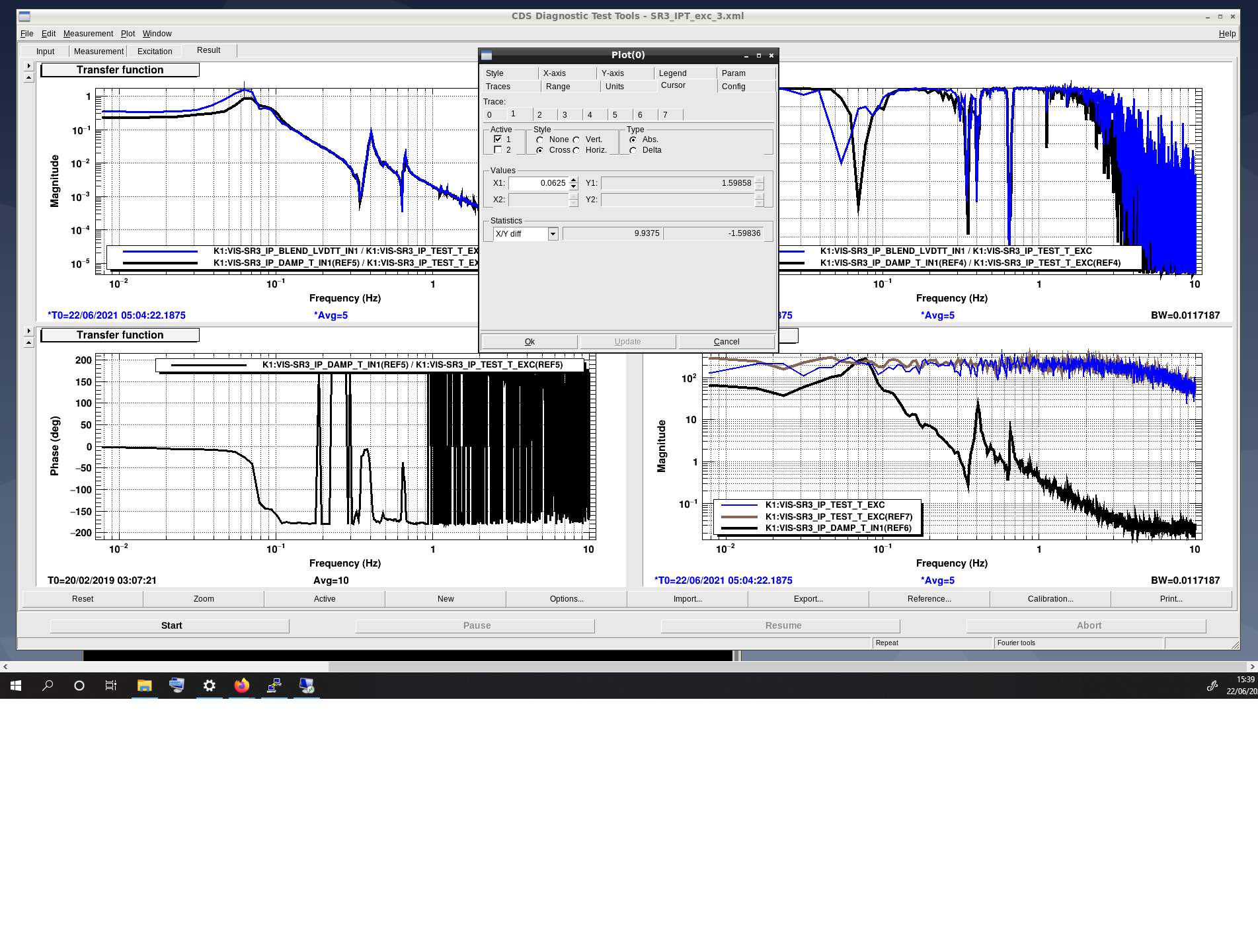
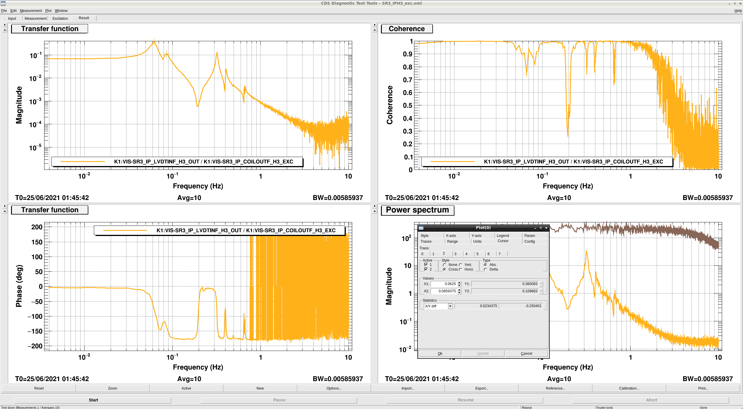
The following step was to remove 1168 g from the +X side (1 ×10 mm × 30° + stud + washers + nut) and measured TFs again with the following result:

  • IP-L:  86 mHz
  • IP-T:  63 mHz
  • Difference: 23 mHz
  • Resolution: 10 mHz
  • File: with _3

In these experiements the difference between the resonance frequencies in L and T remain 23 mHz approximately.

Images attached to this comment
fabian.arellano - 11:59 Friday 25 June 2021 (17281) Print this report

I investigated the asymmetry in the IP-L and IP-T resonance frequencies by measuring the transfer functions at the individual LVDT-actuator units H1, H2 and H3 separately. As can be seen in the plots attached, the lowest resonance frequencies in each case are:

  • H1: 82 mHz,
  • H2: 62 mHz,
  • H3: 62 mHz.
  • Frequency resolution: 5 mHz.
  • Temperature: 23.0°C (O3GK T = 23 °C).

The resonant frequency in the IP_H1 transfer function is 20 mHz higher than in the H2 and H3 measurements! This suggests that we may be able to reduce the asymmetry by putting ballast mass on the IP just above the H1 LDVT-actuation unit, which is nearby one of the IP legs.

Images attached to this comment
Search Help
×

Warning

×