This work is part of the ticket of #432.
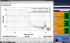
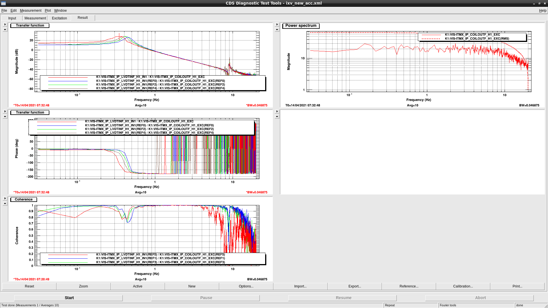
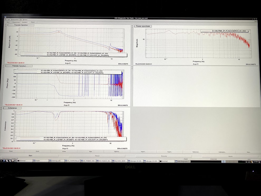
Today we began to tune the resonant frequency of the new accelerometer before making the servo filter for that. Diaggui file to check the resonant frequency is "/users/Miyo/dropbox/LOG/210414/ixv_new_acc.xml". Please note that we used LVDT signal of IP because we forgot to prepare the LVDT distributor for new ACC. Red line in FIG1 shows the transferfunction of the pendulum on which we totaly put 6 weight according to Takahashi-san. Resonant frequency is 0.35 Hz. We need more weights on the pendulum to set lower frequency around 0.2 Hz as we did in prototype reported in klog#14809 and klog#14794 because pendulum used today was made of beryllium copper which is heavier than the prototype. Considering other VIS schedules, we are going to do the rest work in next week.
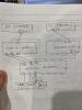
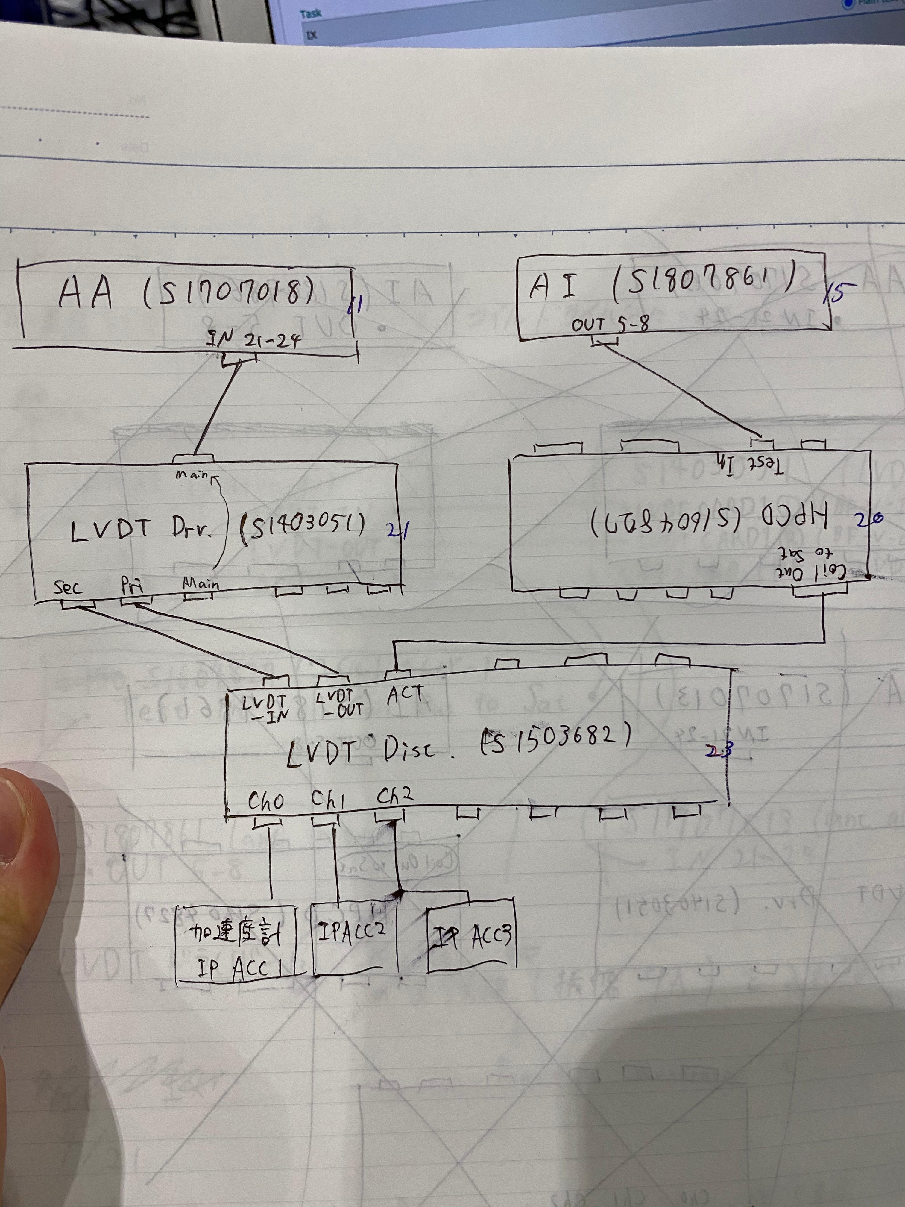
(1)Install new LVDT distributer(S1503682) at 23 in IXV1 rack.
(2)Connect the accelerometer to ch0 of this LVDT distributer.
(3)Connect the LVDT driver(S1403051) to the LVDT distributer. Sec to LVDT-IN. Pri to LVDT-OUT. This LVDT driver is connected to IN 21-24 of AA(S1707018) from Test In.
(4)Connect the HPCD(S1604827) to the LVDT distributer. Coil Out to ACT. This HPCD is connected to OUT 5-8 of AI(S1807861) from Main.
The picture below shows the wiring diagram.
We check the transferfunction of the accelerometer.
See the figure below.
The red line shows the transferfunction of the accelerometer connected to LVDT distributer. The blue line shows the transferfunction of the accelerometer connected to IP system. As you can see, the peaks of the two transferfunctions are about the same. However, the phase of the red line is π out of phase with the blue line. I think I have connected the wiring somewhere in reverse, but that is not a serious problem.
Takahashi, Miyo
Summary
1. Thanks to Sugiyama-kun's preparation, we were able to adjust the resonant frequency of H1 folded type accelerometer to the target value of 0.2Hz today.
2. Although the resonant frequency of H2 and H3 has not been adjusted yet, the LVDTs driver for the three accelerometers in ITMX suspension, including H1, have been adjusted. So we can tune the frequency when we have time.
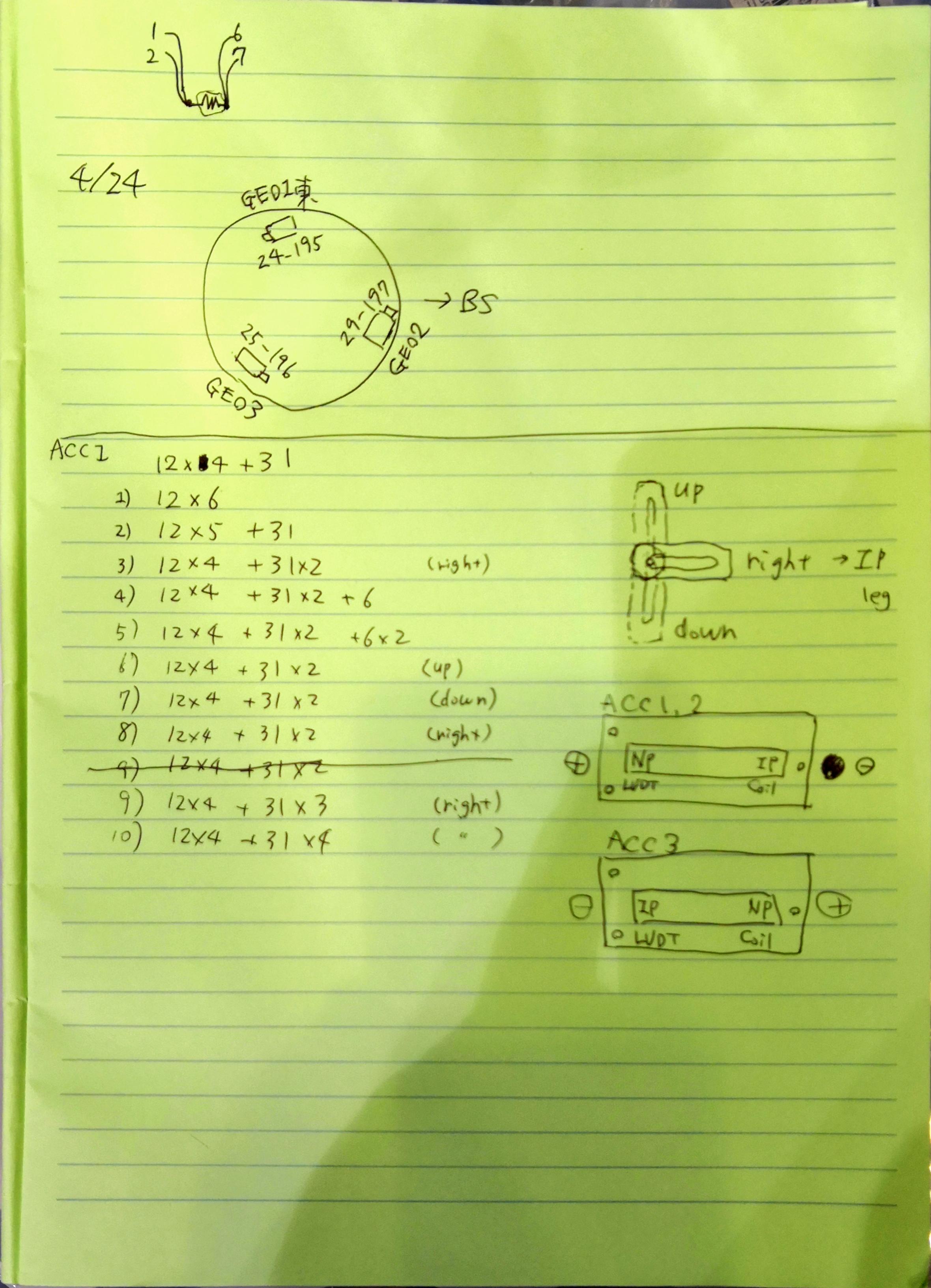
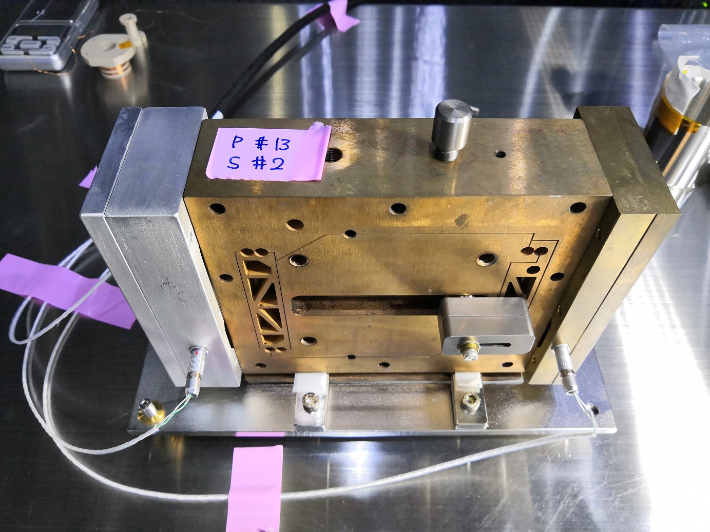
1. H1 folded accelerometer
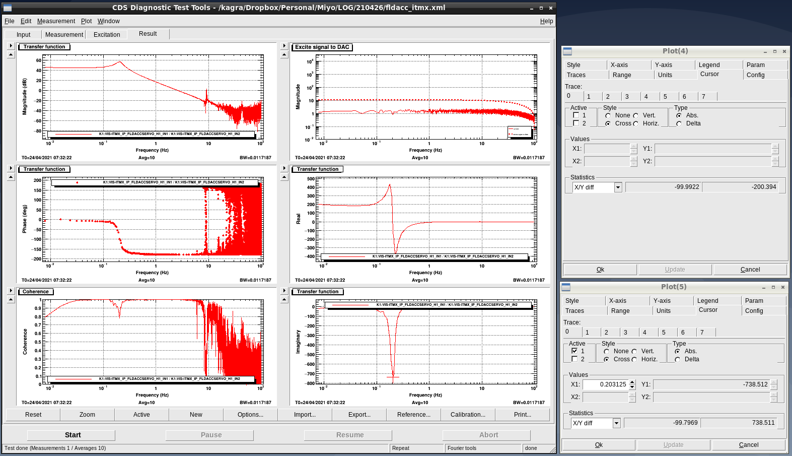
The resonant frequency of H1 could be adjusted by putting some weights on it as shown in Fig. 3. Please refer to Takahashi-san's handwritten log attched in Fig.2 and the Diaggui file in /user/Miyo/dropbox/LOG/210426/ for details. After the final adjustment, we measured the transfer function, but we did not optimize the dynamic range of the LVDT, so we spent the rest of the day adjusting the LVDT driver, as described below.
2. Adjustment of LVDT dynamic range
The rest of the day was spent optimizing the gain and phase of the LVDT driver (S1403051) so that the LVDT signal would not saturate the ADC at the maximum tilt of the accelerometer pendulum. The procedure is as follows. First, the accelerometer was released and tilted to one side or the other. At that time, the accelerometer tilted to a certain inclination and then settled down, so we adjusted the gain and phase of the LVDT so that the value at that time would not be saturated by the ADC. The adjustment was done as follows. First, we turned the gain adjustment knob to set the count to about 30000. After that, turn the phase adjustment knob so that the count value is maximized. If, after optimizing the phase, the count increases or decreases, turn the gain adjustment knob to 30000 counts again. When we could confirm that the LVDT signal is not saturated on one side, then tilt the accelerometer to the other side and confirm that it is not saturated. If it is saturated, adjust the gain to 30000 counts. In this way, we adjusted the LVDT signal not to be saturated when the accelerometer pendulum was tilted on both sides.
After the adjustment, the transfer function was measured again only for H1. As shown in Fig. 1, the resonance frequency could be adjusted to 0.20 Hz.
Next
we will do the resonant frequency tuning work for H2 and H3


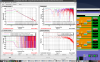
We tuned the three accelerometers.
2021.5.25
・H2
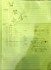
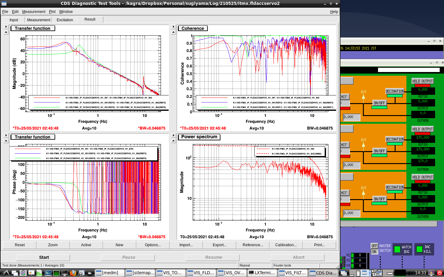
Takahashi-san attached some weights to H2, one 3.0g, one 6.0g, three 31.0g, and two 34.6g weights.
I measured the transfer function. Please see Fig1 and refer to the diaggui file "/users/sugiyama/dropbox/Log/210525/itmx.fldaccservo2".
The red line is the transfer function with the resonant frequency tuned to 0.2Hz.
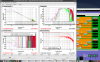
・H3
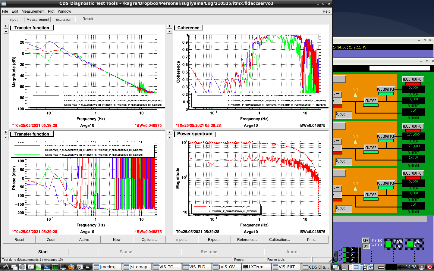
Takahashi-san attached some weights to H2, one 6.0g, two 12.0g, and one 34.6g weight.
I measured the transfer function. Please see Fig2 and refer to the diaggui file "/users/sugiyama/dropbox/Log/210525/itmx.fldaccservo3".
The red line is the transfer function with the resonant frequency tuned to 0.2Hz.
Coherence in low frequency is bad. So, we tuned H3 with prediction.
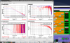
2021.5.26
・H1
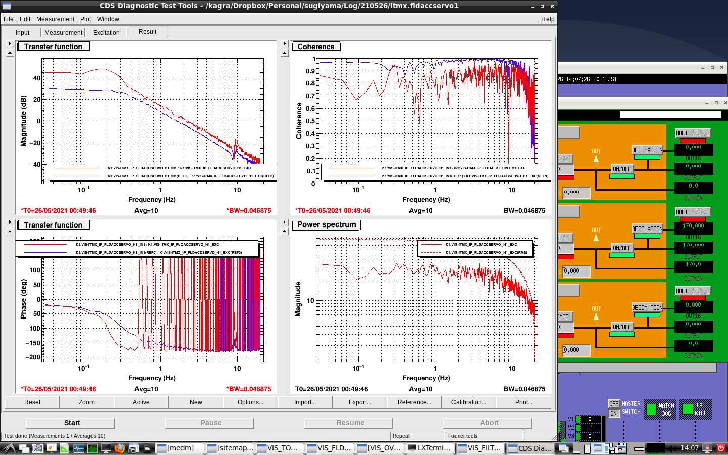
H1 was tuned before, but its transfer function is higher than 0.2Hz. So, We tune it again and measure its transfer function.
Please see Fig3 and refer to the diaggui file "/users/sugiyama/dropbox/Log/210526/itmx.fldaccservo1".
The red line is the transfer function with the resonant frequency tuned to 0.2Hz.
Finally, H1 was attached one 3.0g, two 12.0g, three 31.0g, and one 34.6g weight.
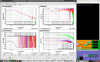
・Three accelerometers
After we tuned three accelerometers, three accelerometers were placed side by side and covered with a container.
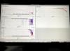
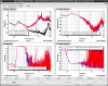
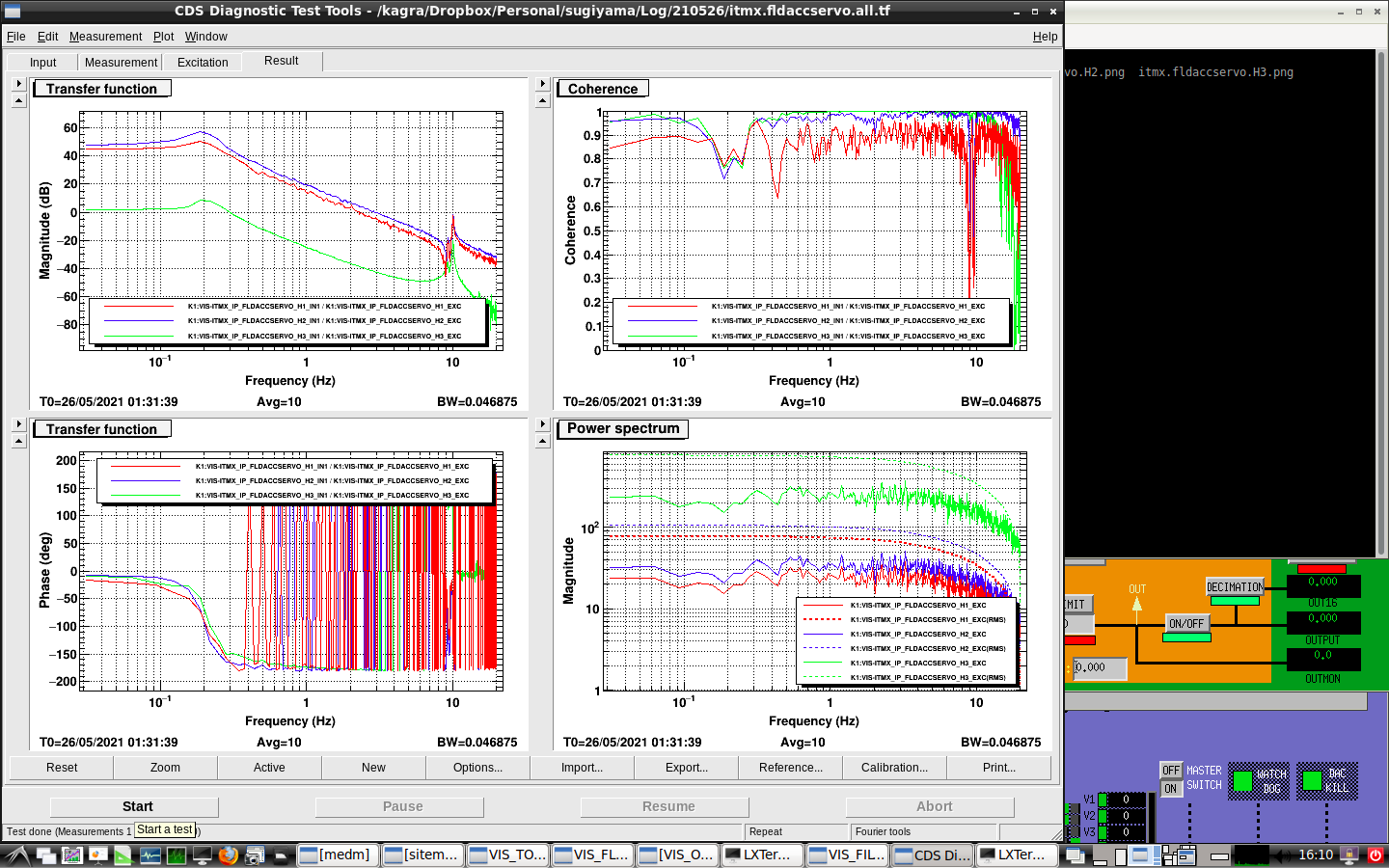
Then I measure the transfer function of the three accelerometers at the same time.
Please see Fig4 and refer to the diaggui file "/users/sugiyama/dropbox/Log/210526/itmx.fldaccservo.all.tf".
The red line is H1's transfer function, the blue line is H2's transfer function, the green line is H3's transfer function.
H3's coherence is better than yesterday's. So, we tuned all accelerometer's transfer functions to 0.2Hz.
・Problem
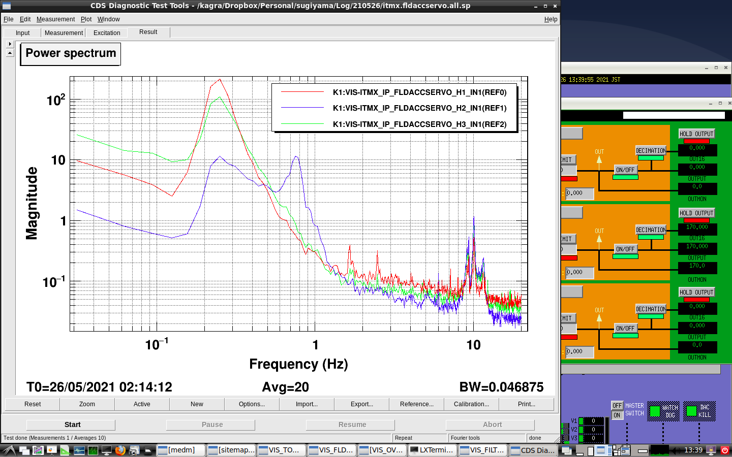
I measure the spectrum of H1, H2, and H3.
Please see Fig5 and refer to the diaggui file "/users/sugiyama/dropbox/Log/210526/itmx.fldaccservo.all.sp".
H2's spectrum has two peaks. The left peak is almost 0.2Hz. But, H2 has one more peak. This is the problem.
We will check the source of the problem.
We check the transfer function of the new accelerometers which will be installed on IP of IX.
·H3
H3 has the problem.
We can't actuate H3 because the number of turns of its coil is very small.
So, we replace the accelerometer. We tune in later.
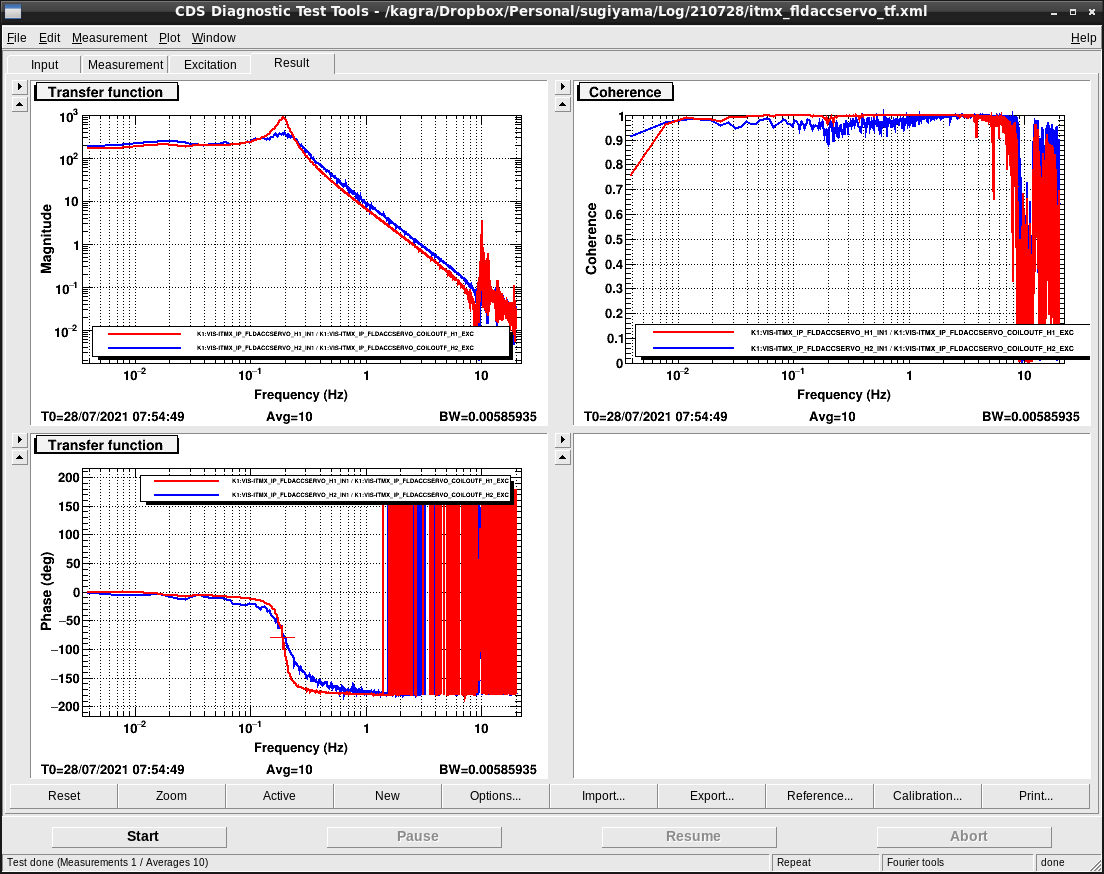
·H1, H2
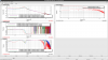
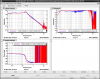
We measure the transfer function. Please see Fig1 and diaggui file "/users/sugiyama/dropbox/Log/210728/itmx_fldaccservo_tf.xml".
The red line is the transfer function of H1 and the blue is H2. Their resonant frequency is around 0.2Hz which is the target.
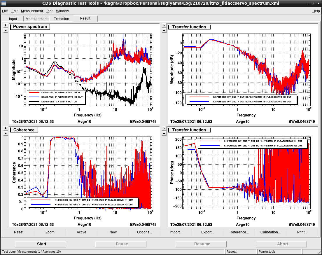
After that, we insert a simple servo filter and measure the spectrum.
Please see Fig2 and diaggui file "/users/sugiyama/dropbox/Log/210728/itmx_fldaccservo_spectrum.xml".
The red line is the spectrum of H1, the blue is H2, and black is the spectrum of geophone installed on the near ground.
As you can see, H1 and H2 are capable of measuring microseism. So, the accelerometer can use for IP damping.
·Next work
We will optimize the servo filter, and tune H3.
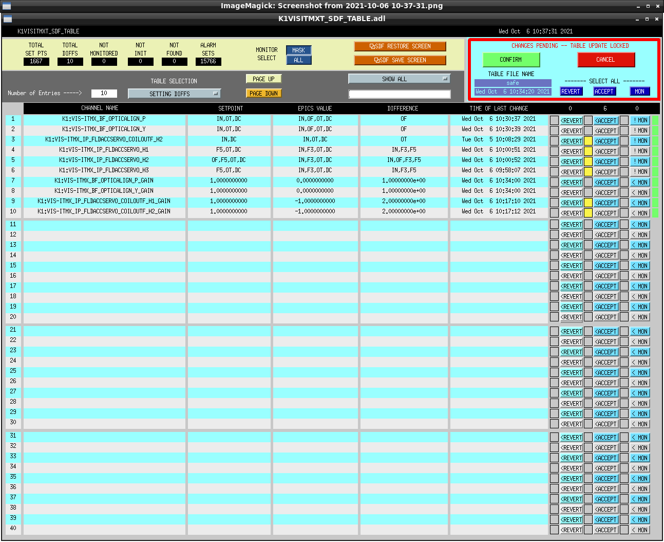
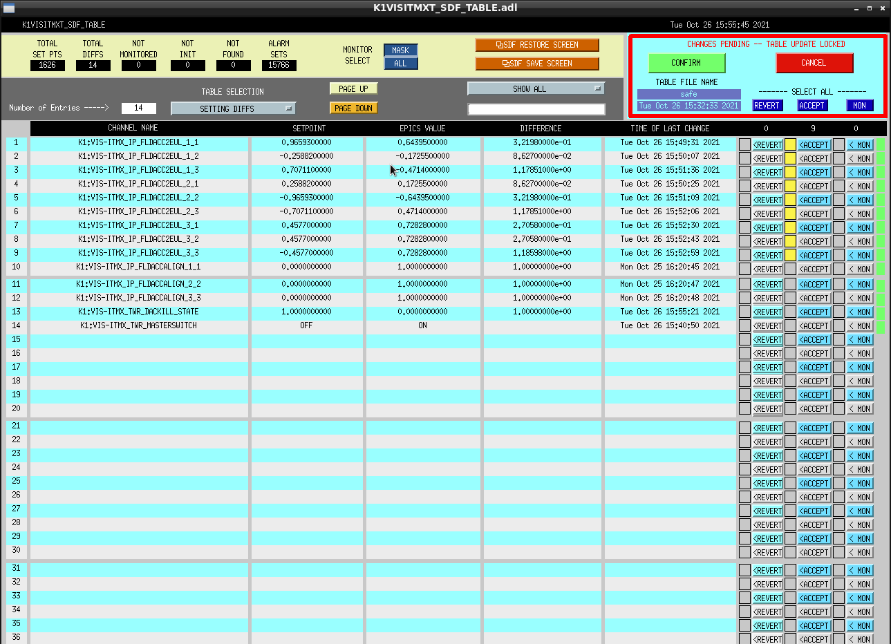
Then I accepted the SDF.
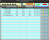
Then, I accepted the SDFs.
Please check the following figures.