Takahashi R., Sato N., Miyo, Akutsu with help of Tanaka K., Hirose, Koyama, Tanioka
Abstract
Recovered the yaw picomotor range for the MCo suspension, and aligned roughly the IMC mirrors and suspensions, and so observed the MCo transmission light beam was flashing in higher order modes (see the movie for the flashing at imc-upgrade in slack).
Re-positioning the MCo suspension
Some additional information may be provided in the other posts. As found in the mid of March (16225), the yaw picomotor in the MCo suspension was at the end of its range, but unfortunately we wanted to rotate MCo in that direction more (see also 16300) for continuing the IMC re-alignment. The easiest way to continue it would be to just insert a shim or collar at the opposing to this picomotor's tip, but eventully we gave up this idea, as this way would make more twist within the MCo suspension. Instead, Aso-san proposed to rotate (and shift if necessary) the whole structure from the MCo suspension frame to recover the picomotor range and so eliminate the twisting.
But we found it was not so easy to reposition the suspension frame due to the jigoku-zaiku manner; the base plate of the suspension frame, the bottom plate of the frame, and the top surface of the bread board in the MCF chamber were fixed with screws in a complicated way. So Yano-san had designed a set of special jigs having eight positioners (KL02 by Thorlabs) to precisely push the four corners of the bottom the suspension frame for repositioning. The jigs were finally delivered yesterday.
Fortunately there has been a beam spot at MCe, so we used this spot location as a reference. The spot was displaced from the center to the left edge (i.e. in the minus X direction) of MCe (see 16300), so our method of repositioning was as follows:
- Rotate the suspension frame with the jig until the beam spot on MCe reached about the right edge (i.e. in the +X direction).
- Rotate manually the picomotor until the beam spot on MCe reached about the left edge.
- Go to 1 until the picomotor range became about 5-6 mm, or rather, until the twisting in the suspesion was mitigated sufficiently; in other words, until the side edges of two mechanical parts (the picomotor is attched to one of these; these are suspending the IM stage) were aligned each other. Takahashi-san judged this. While this work, there were some troubles; for example, at some point, the picomotor could not push this part any more. This was also resolved by Takahashi-san; some small parts that were used for the past trials were still left there, and so on. I think Takahashi-san can report it more in detail, if possible.
Thanks to Zoom, the team at MCF (Takahashi, Sato, Akutsu) and MCE (Tanaka, Hirose, Kotani, Miyo) could have comminucation, and the MCF team could see the beam spot on MCe that was shoot by the MCE team in real time.
Re-centering the coils for MCo
After the re-positioning the MCo suspension, Takahashi-san and Sato-san re-centered the coils for MCo. Before and after this work, Miyo-kun took some transfer functions to see if this work would change something badly or not. So far no such tendency was found (will be reported by him). By the way, before running the script, we re-centered the MCo oplev, as it was mostly out of the range.
We learned that two of the four mangets were too deep into the coil bobbins, but Takahashi-san judged the gaps between the MCo AR surface and the coil bobbin are still ok even if the max allowable current is applied to each coil (BTW, what are the gaps in numbers??), so we determined not to insert shims to the coil holders.
Re-aligning the IMC
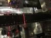
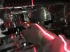
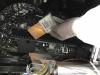
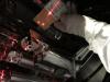
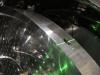
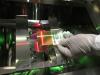
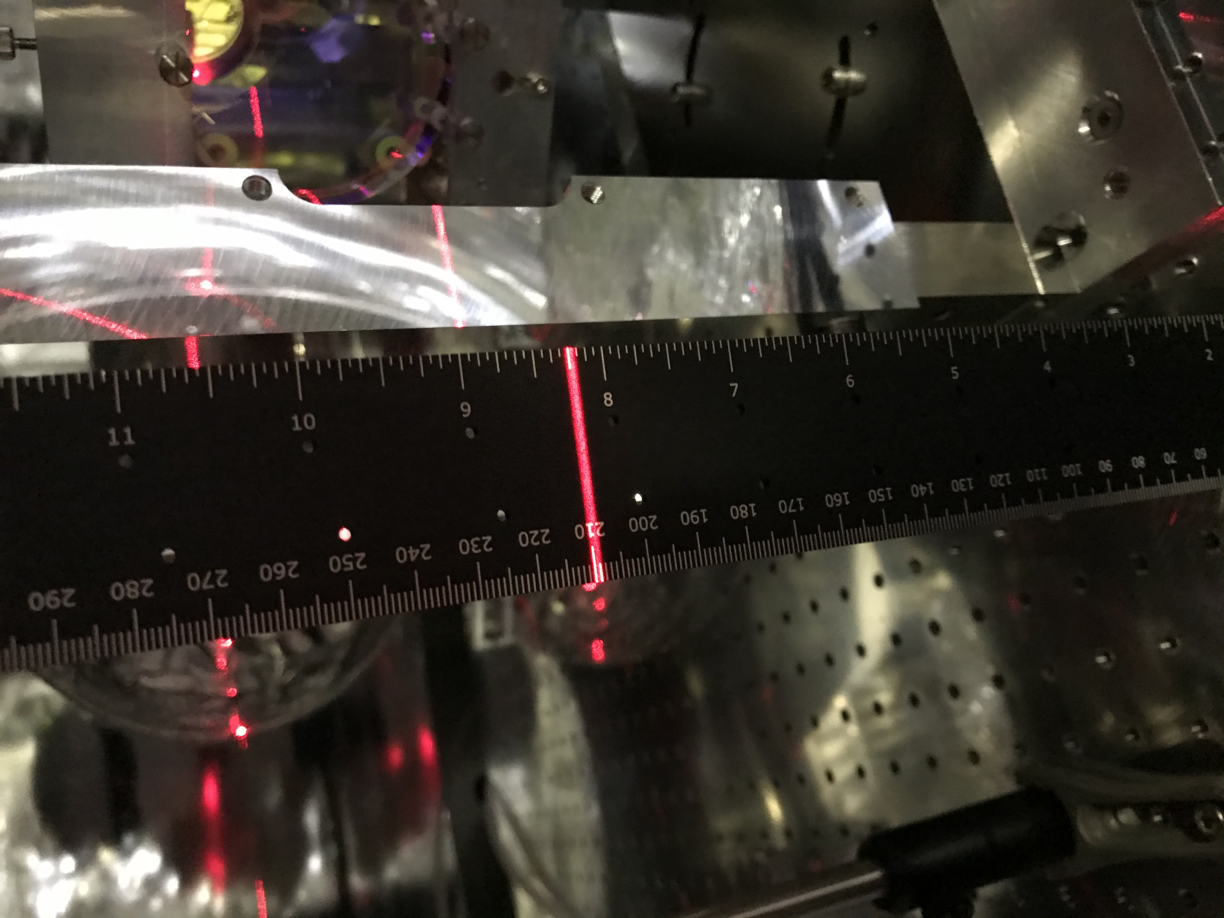
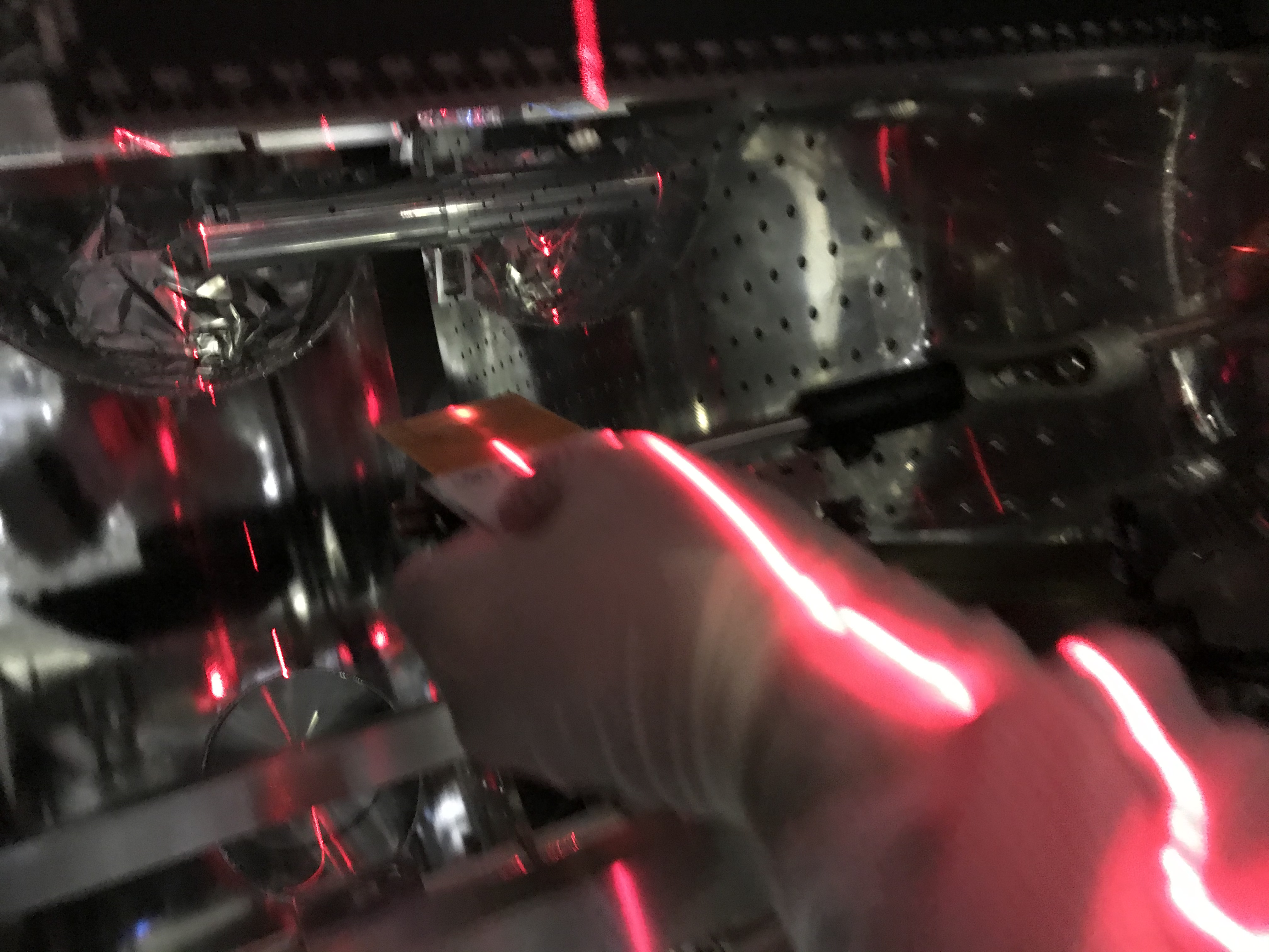
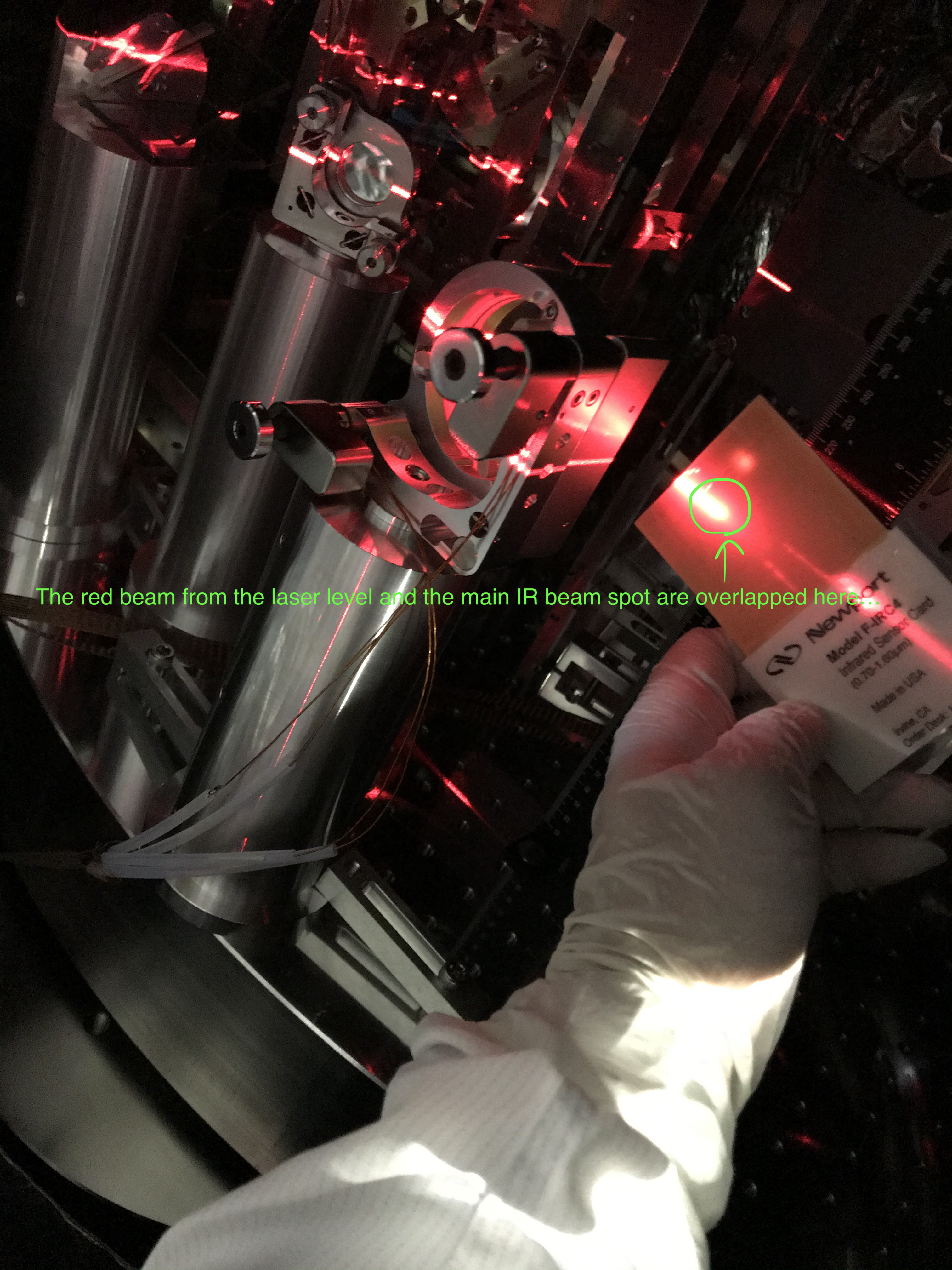
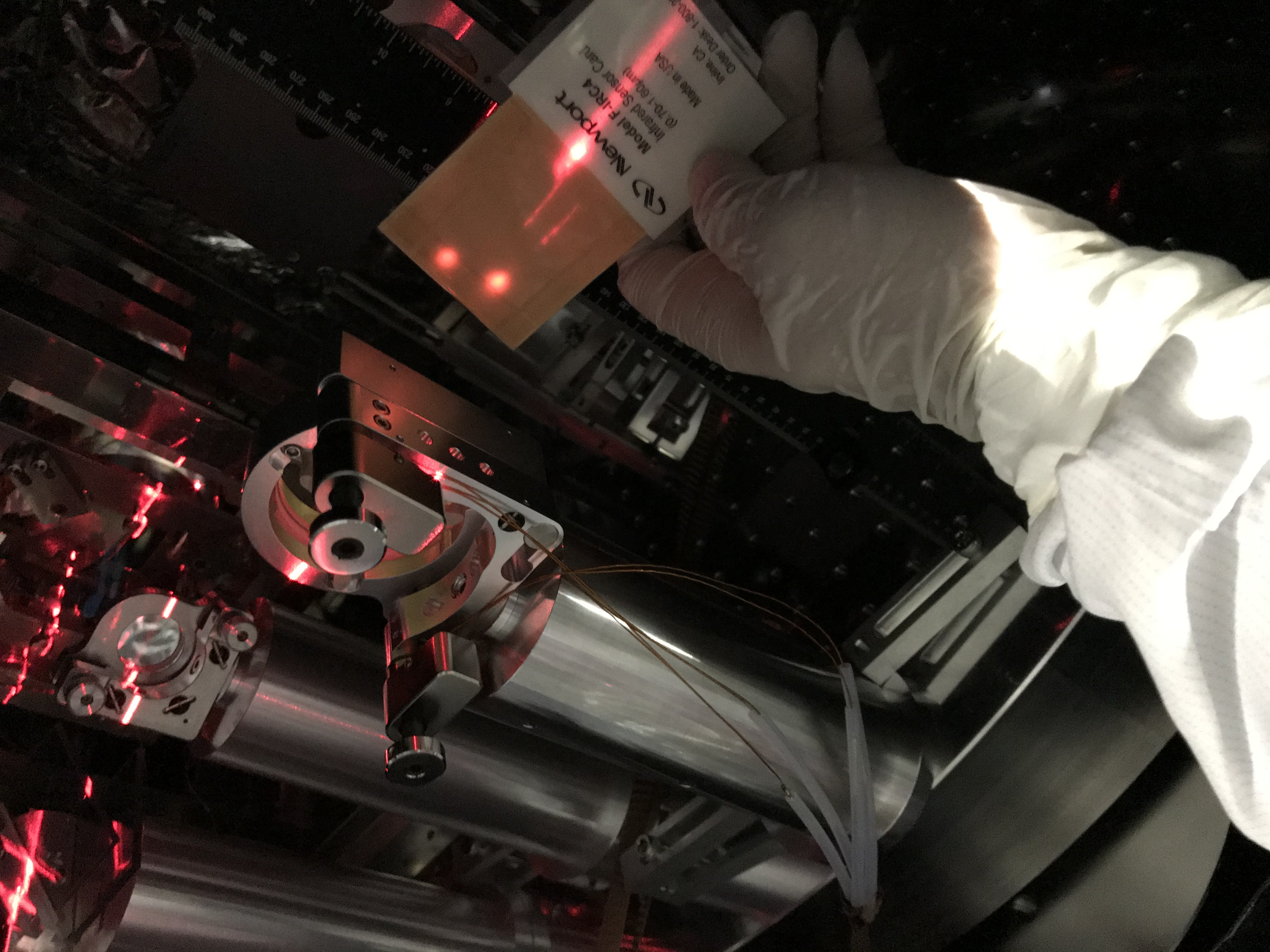
We realign the IMC in the following procedure. Here, all the picomotors were actuated remotely by Miyo-kun. Before starting the main procedure, we re-aligned IP2 in the PSL room so that the 0-th input beam to STM1 through MCi and MCo was flying the way as close as the design (despite our work reported in 16300); we found the beam spot was vertical lower than the nominal (210 mm) height (measured from the top surface of the MCF-IFI inside breadboards), so adjusted IP2 again (Figs. 1 and 2 for the spot between MCi and MCo; Figs. 3, 4, and 5 for the spot in front of STM1). Well, phew, ok, then,
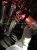
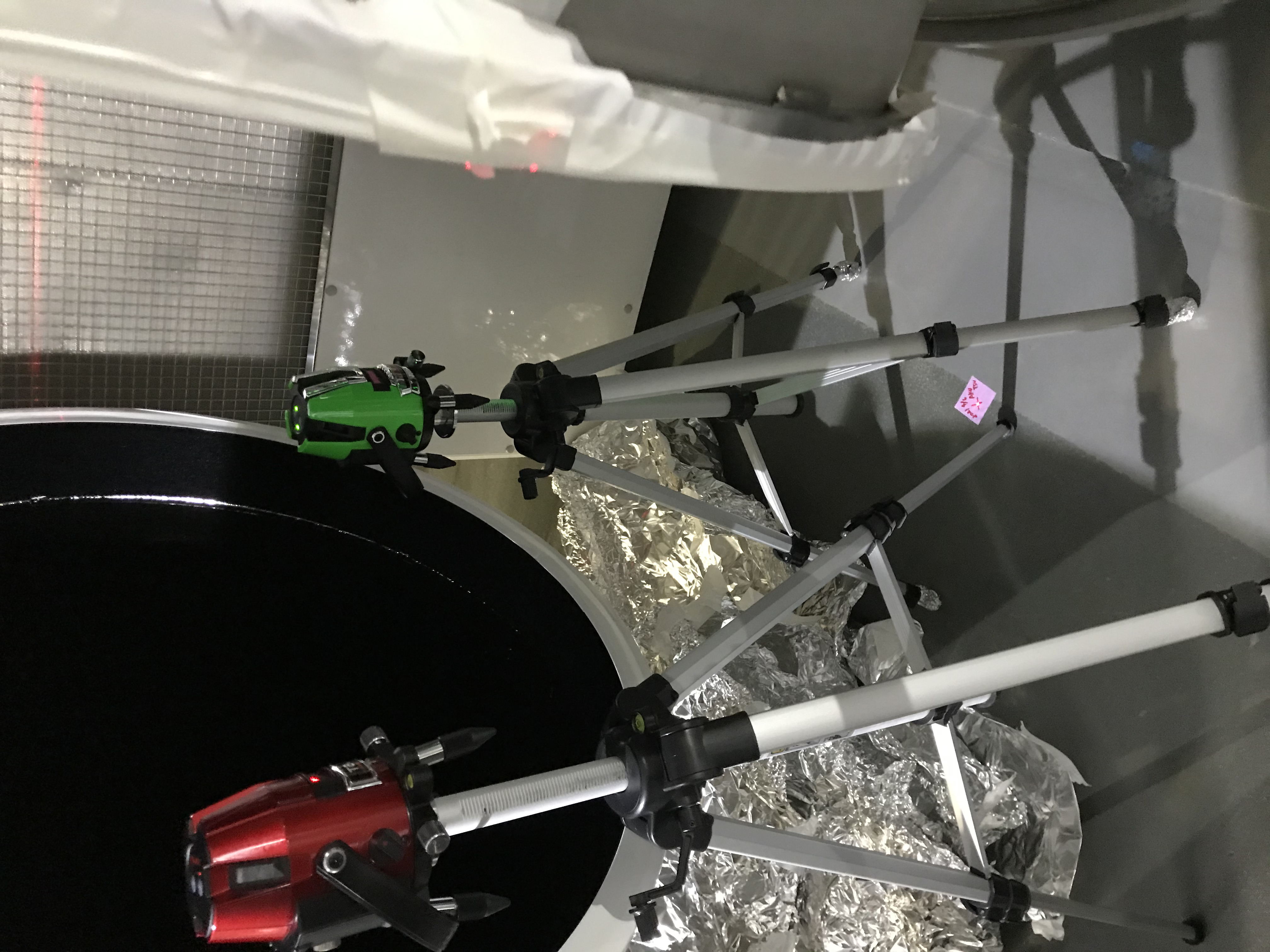
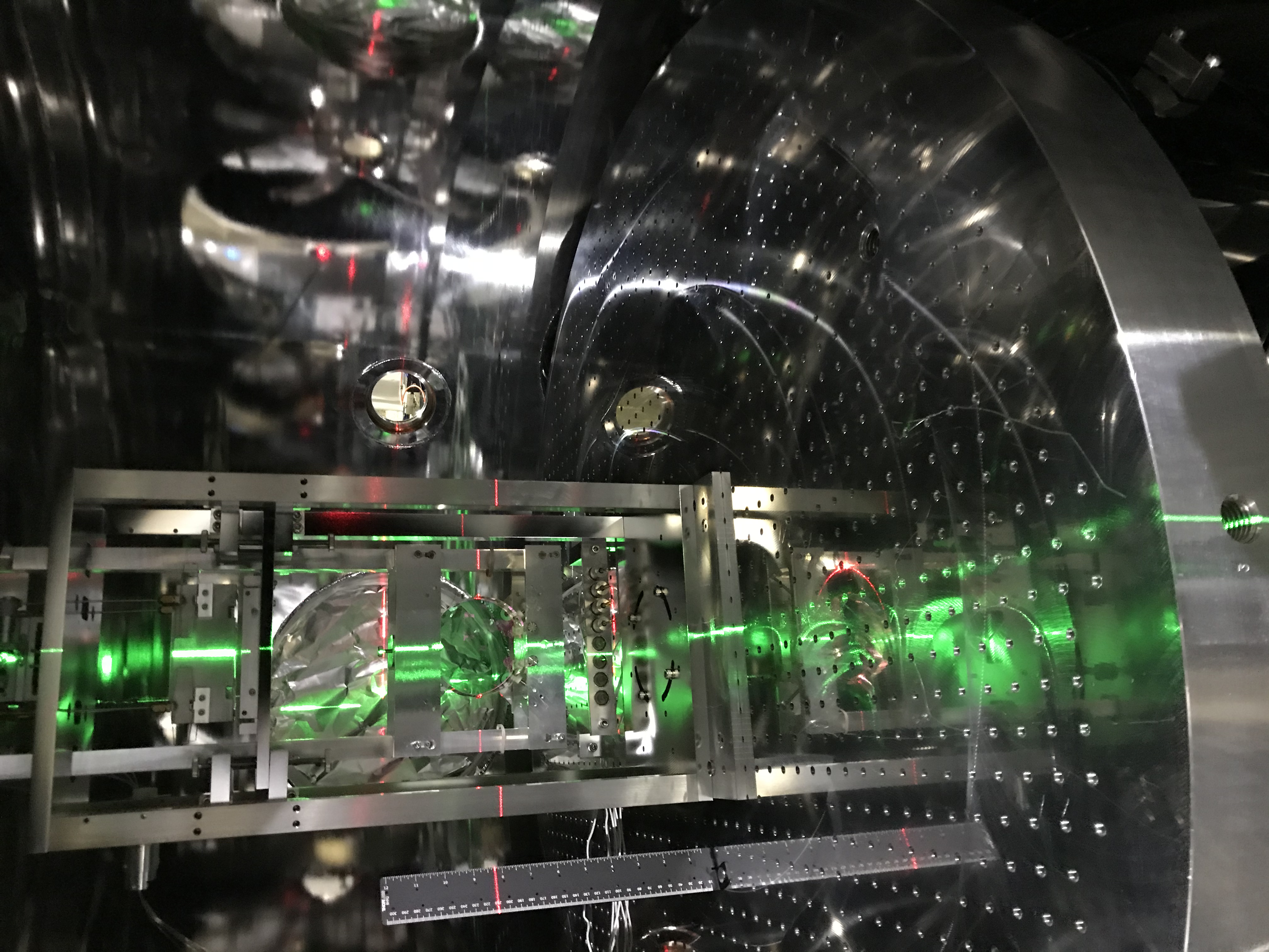
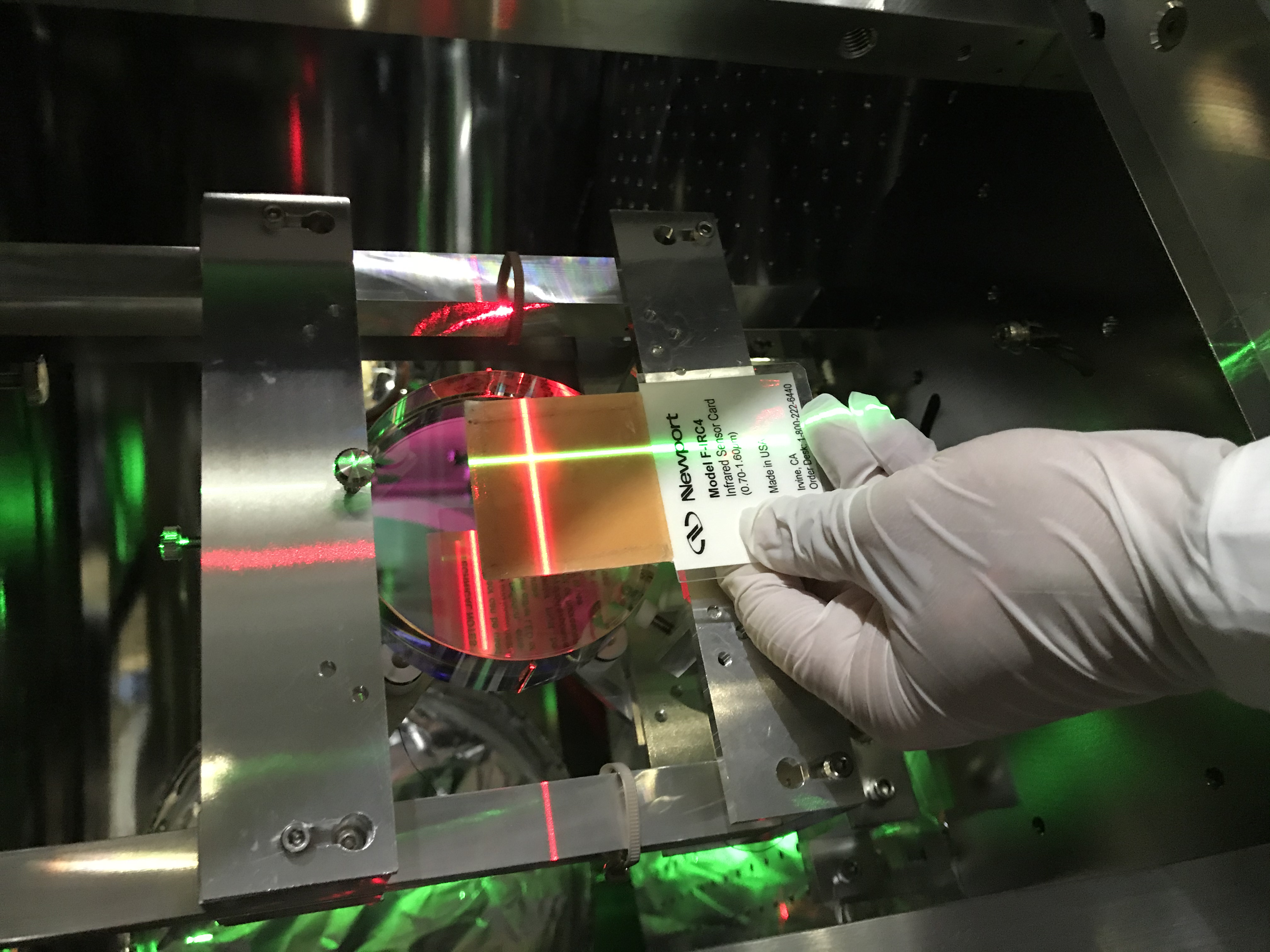
- Actuate the MCo's pitch and yaw picomotors until the beam spot comes to the MCe's center; for this purpose, we set two laser levels in front of MCe so that we can imaginarily mark the vertical (green) and horizontal (red) center of MCe; so the center is recognized as the crossing point (Figs. 6, 7, and 8 for the setup, Fig. 9 for the IR beam spot was on the crossing point).
- Record the MCo oplev pitch and yaw here (if they were out of range, we would need to do re-centering, but fortunately this did not happen).
- Actuate the MCe's pitch and yaw picomotors until the beam spot comes to the MCi center; for this purpose, maybe the most precise way would be to do in the same manner as described in 1, but we went in the side way; actually, it is hard to see the center of MCi. Instead, for pitch alignemnt, we put a vertical ruler on the breadboard in the MCF chamber in-between MCi and MCe, and monitored the beam spot on the sensor card near the vertical ruler; for yaw alignment, we used the 0th-round input beam as the reference, and aligned the MCe's yaw until the 1st-round beam (reflected from MCe and reflected at MCi toward MCo) was overlapped on the 0-th round input beam as much as possible. The background of this yaw method is that I supposed that the 1st beam just after MCi would not still "fill" the tilt of MCi so much, and took advantage of the fact that the MCi tilt might have been "still well aligned" as it was once used to lock IMC. Then we could observe three beam spots on the sensor card inserted in-between MCi and MCo; the 0th, 1st, and maybe 2nd round beams. Slightly took time to distinguish the 1st and 2nd beams. Considering the situation for a while, I determined my mind to align MCi anyhow and see the result.
- Actuate the MCi's pitch and yaw picomotors until the 1st-beam spot comes to the MCe center(note! not MCo center, which is too close to MCi and again hard to see the center as is at MCi), where the 0-th beam spot has been already there and so do the laser levels light beams (so my judge "leaving the laser levels here, as I do not want to move these back to MCF..." would be correct fortunately; sometimes laziness will help you).
Finally, we re-centered the MCi and MCo oplevs again.
I was worried that we would need to do more iterations to even see flashing, but fortunately the transmission beam from MCo to IFI showed flahsing (interfernce pattern), although in varying higher order modes. Let us do finer tuning later!

