Reports 1-1 of 1 Clear search Modify search
VIS (EY)
ryutaro.takahashi - 16:23 Wednesday 17 March 2021 (16276) Print this report
Setup of F1

[Takahashi, Sato, Horiuchi]

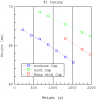
We started the setup of F1.

  1. Lifted up the EQ stop. The end plate for F3 was put on the frame lock.
  2. Repaired the D-sub connector for the BF DPCV.
  3. Lifted down the EQ stop. The end plate for F2 was put on the frame lock.
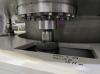
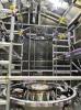
  4. Extended the EQ stop to the F1 stage.
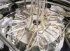
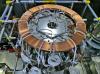
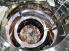
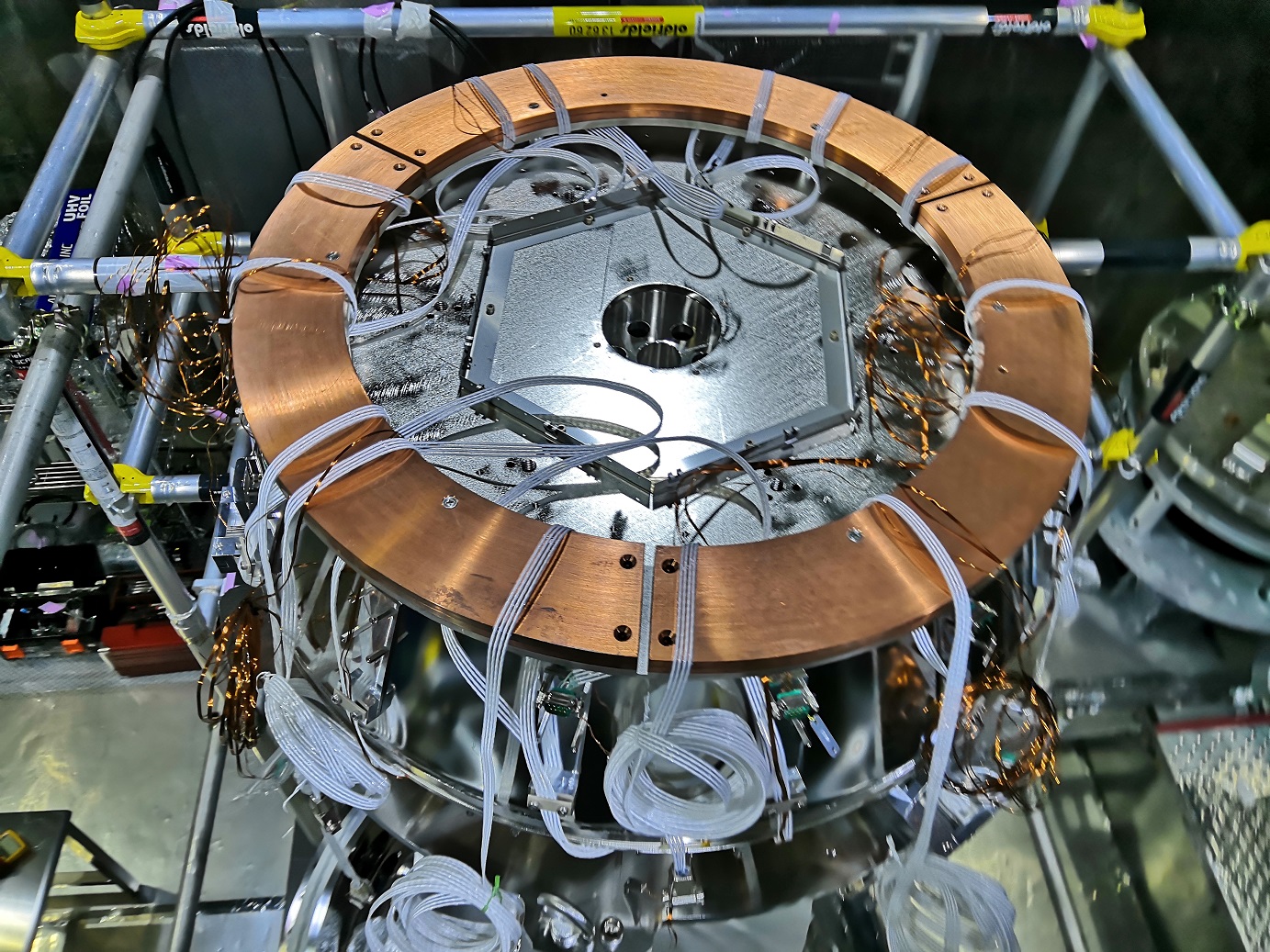
  5. Opened the cup for F1. Removed the old FR blades.
  6. Fixed the small hexagons on the wire #320 with the set collars.
  7. Prepared for the cables between the F1 and F2. Some cables were pepaired.
Comments to this report:
ryutaro.takahashi - 18:48 Thursday 18 March 2021 (16288) Print this report

[Takahashi, Sato, Horiuchi]

  1. Attached the new blades for FR.
  2. Inserted the wire #320 into the EQ stop.
  3. Mounted the F1 on the EQ stop hooking the wire to the receptacles. The height of F1 was set to 70mm.
  4. Continued the repair of cables and implemented the connector covers. Some cables completed were put between the F1 and F2.
ryutaro.takahashi - 20:23 Tuesday 23 March 2021 (16309) Print this report

[Takahashi, Sato, Horiuchi]

  1. Finished the cabling between the F1 and F2.
  2. Released the F2.
  3. Calibrated the LVDT in the F1. The height of secondary coil was shifted from -10mm to -16mm (plot #1).
  4. Tuned the F1 at the mid point (43mm in height) of FR using the lowest mode of filter chain (plot #2). 
  5. Checked the range of FR (plot #3).
Images attached to this comment
ryutaro.takahashi - 20:13 Wednesday 24 March 2021 (16321) Print this report

[Takahashi, Sato, Horiuchi]

  1. Behavior of the F2 was not natural. Lifted up the EQ stop so as to see the bottom of F2. Adjusted the horizontal position of secondary coil to prevent touching the prinary coil.
  2. Lifted down the EQ stop.
  3. Tuned the F1 again using the highest mode of filter chain (plot). The base weight was 89.3kg. The F2 keystone jumped due to the large tilt of F2 at the additional weight less than 300g.
  4. Fixed the additional ballast of 660g on the cup of F2.
Images attached to this comment
naohisa.satou - 21:31 Wednesday 24 March 2021 (16323) Print this report

Addendum:
Wiring the release sensor (outside the vacuum chamber)

1. Installed the Ex-I/O chassis (JGW-E1706268) in the rack. 
2. Wired from the chamber feedthrough to the Ex-I/O chassis. 
(I did not wire from the Ex-I/O chassis to the DGS.)
 

Non-image files attached to this comment
ryutaro.takahashi - 20:04 Thursday 25 March 2021 (16329) Print this report

[Takahashi, Sato, Horiuchi]

  1. Measured the LVDT spectrum of F1 and F2 with fixed keystones.
  2. Closed the cup of F1. Tuned the weight on the F2 so that the keystone height can be 66mm. The base weight was not 89.3kg but 87.9kg.
  3. Hung the F1 by the crane. Tuned the weight on the F2 again.
  4. Fixed the additional weight (440g x3) on the F2.
  5. Cabled around the F1.
  6. Attached the Cu ring onto the cup of F1.
  7. Checked the conectability of the cables.
Images attached to this comment
naohisa.satou - 8:50 Friday 26 March 2021 (16336) Print this report

8. We wired release sensor signal line from the Ex-I/O chassis to the DGS.

(The DGS connector I connected to was handwritten with "In4".)

ryutaro.takahashi - 17:20 Tuesday 30 March 2021 (16353) Print this report

[Takahashi, Sato]

  1. Replaced the cone bellows. It was necessary to remove the piston head temporaly. One of three has been done by Horiuchi-san on 26th.
  2. Lifted down the EQ stop. The F1 stage was put on the frame lock.
  3. Extended the EQ stop to the top ring.
  4. Lifted down the EQ stop so as to access the BF. We could not put the top ring on the frame lock due to the wire for the cryo-payload.
  5. Checked the conectability of BF-LV line. #3-8, #4-9 pins were not available. The terminator was connected to the BF-DCPV line to employ the empty pins.
  6. Lifted up the EQ stop. The F1 stage was put on the frame lock.
Images attached to this comment
ryutaro.takahashi - 21:20 Wednesday 31 March 2021 (16366) Print this report

[Takahashi, Sato]

  1. Disassembled the EQ stop to the top ring.
  2. Lifted up the EQ stop. The end plate for F2 was put on the frame lock.
  3. Hung the F1 by the crane.
  4. Fixed the F2 keystone by the long nut and studs bolt. Released the F2.
ryutaro.takahashi - 21:03 Tuesday 11 May 2021 (16712) Print this report

[Takahashi, Sato, Ito, Sugiyama]

  1. Lifted down the F1 onto the EQ stop. Removed the long nut and studs bolt from the F2.
  2. Replaced the broken cables (CRY-01, CRY-12) between the F1 and F2.
  3. Released the F2.
  4. Lifted down the EQ stop. The end plate for F1 was put on the frame lock.
  5. Extended the EQ stop to the top ring.
  6. Put the F1 damper (magnet ring) on the F1 cup.
  7. Inserted the wire #319 for F1 and the wire #332 for damper. Fixed the wires with the wire clamp on the top ring.
Images attached to this comment
ryutaro.takahashi - 20:34 Wednesday 12 May 2021 (16727) Print this report

[Takahashi, Sato, Ito, Sugiyama]

  1. Lifted up the F1 with the crane a little, and released the bottom stopper. The F1 sat down the release sensors.
  2. Implemented the cables along the wire between the F1 and the top ring.
  3. Checked the connectability of cables. One cable was repaired.
  4. Released the side stoppers for F1.
  5. Lifted down the F1 stage with crane. The top ring was put on the frame lock.
  6. Adjusted the horizontal and rotational positions of the frame lock.
Search Help
×

Warning

×