Miyoki, Kokeyama, Akutsu
Abstract
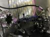
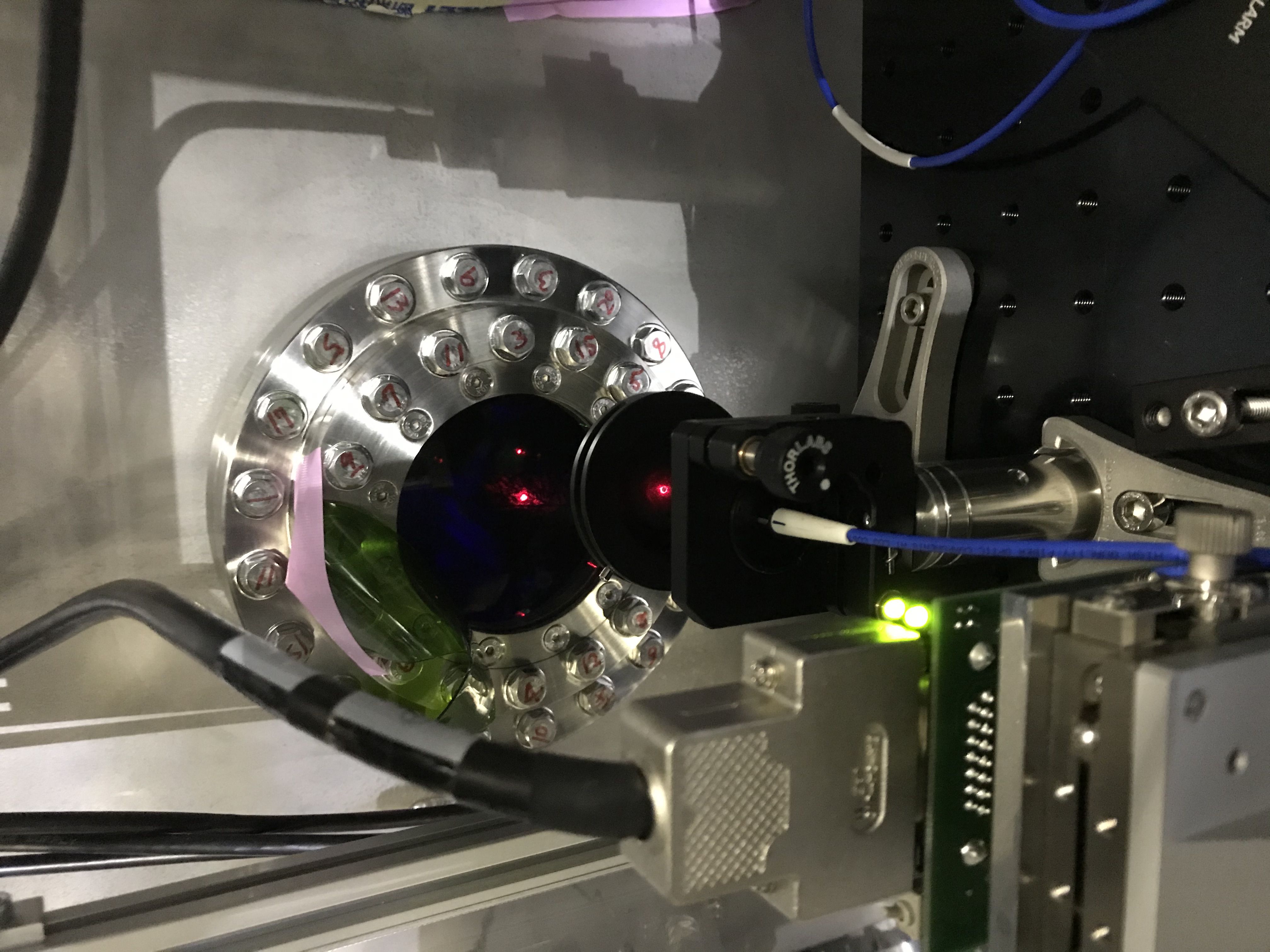
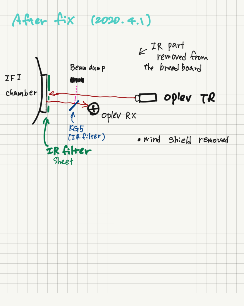
After the alignment works for the interferometer the last week, the IMMT2 oplev became unusable (13886 and 13887). Today we checked the situation again, and judged that a serious surgery was needed if we would like to revive the oplev. So far we succeeded it (Fig. 3). On the other hand, now we are slightly worried about that the oplev range might not be enough. Let's see. We also took care of the IR contamination, and it seems succeeded.
Details
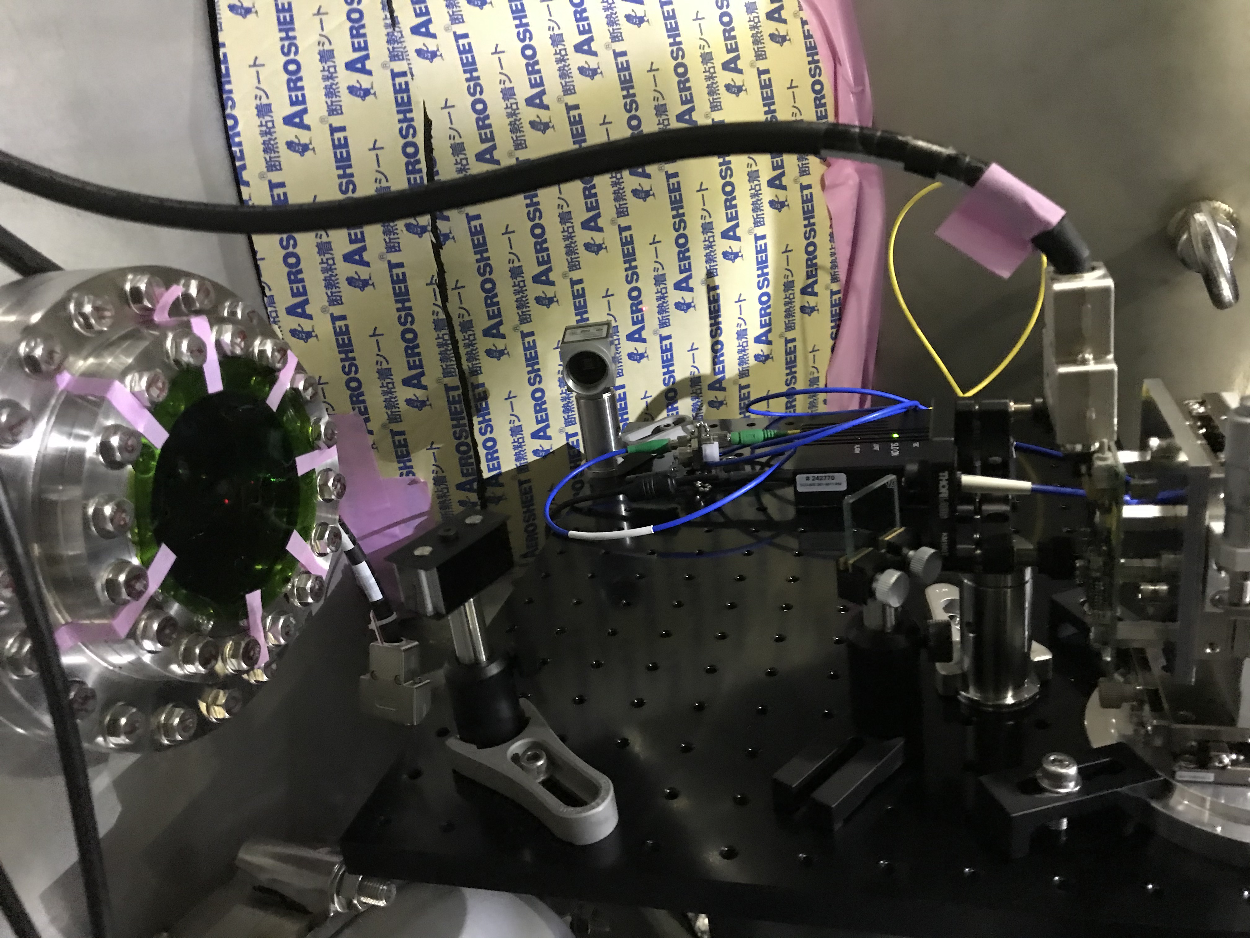
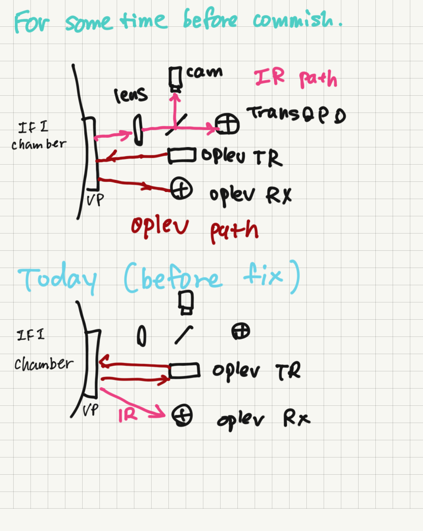
- Before our work, the light beam coming back reflected from IMMT2 could not reach the oplev's QPD; it was shut by the edge of the holder for the light-beam's transmitter, which was located in front of the QPD (see 13887). By tweaking the knobs on the transmitter's holder, we could vary the beam direction, but that was not enough to resolve this difficult situation. After some discussion among us, we finally determined to move bravely the transmitter so as that the reflection beam could go thourgh the side of the transmitter's holder.
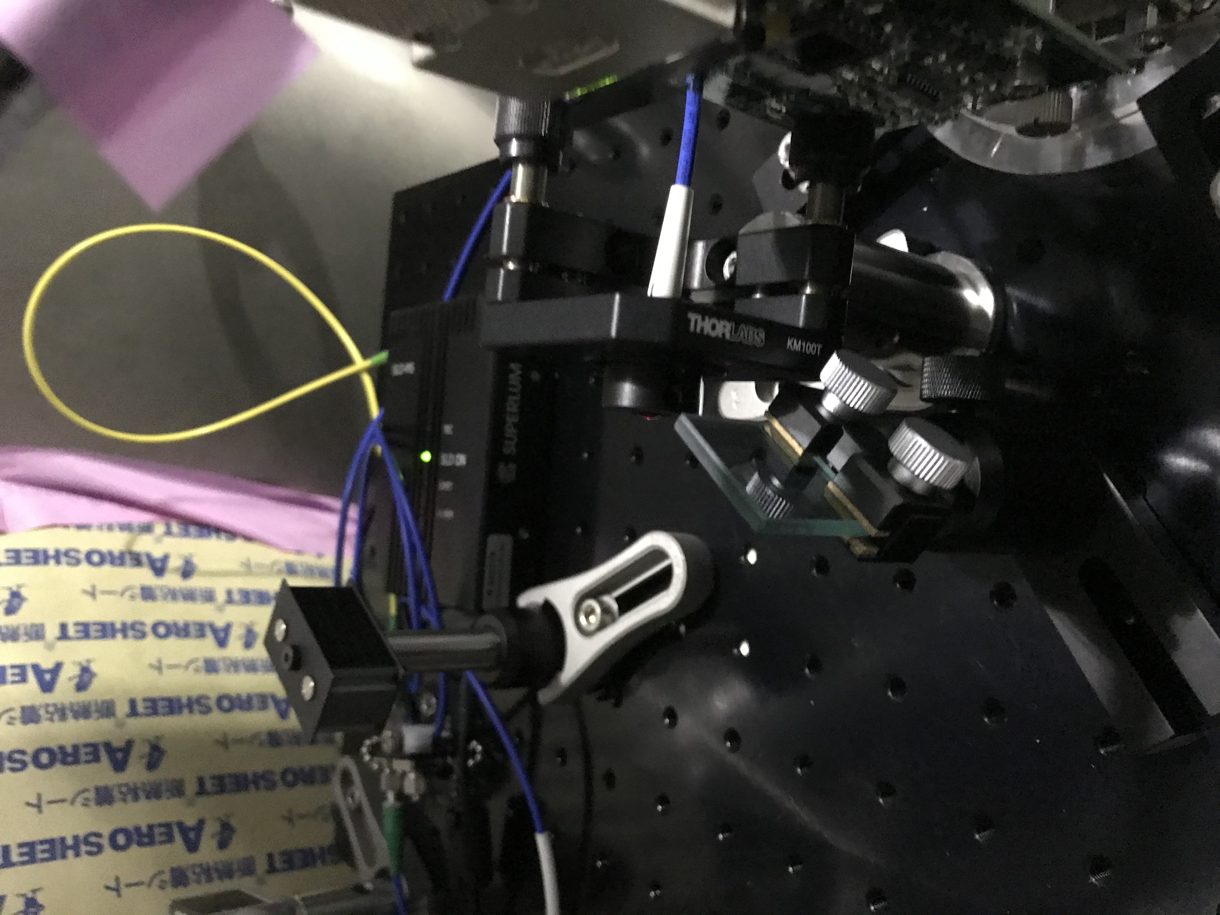
- Before moving the transmitter holder, we detached some of the optics for the IR beam path. Actually, at this time, the IR beam was hitting anywhere inside the IFI chamber, where the IMMT2 suspension has been contained, and some IR fringe pattern was only seen... in short, it was not usable as IMMT2 IR transmitting beam. This was why we detach the optics relavant to the IR beam path, and widen the space on the oplev bench.
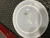
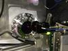
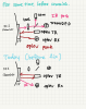
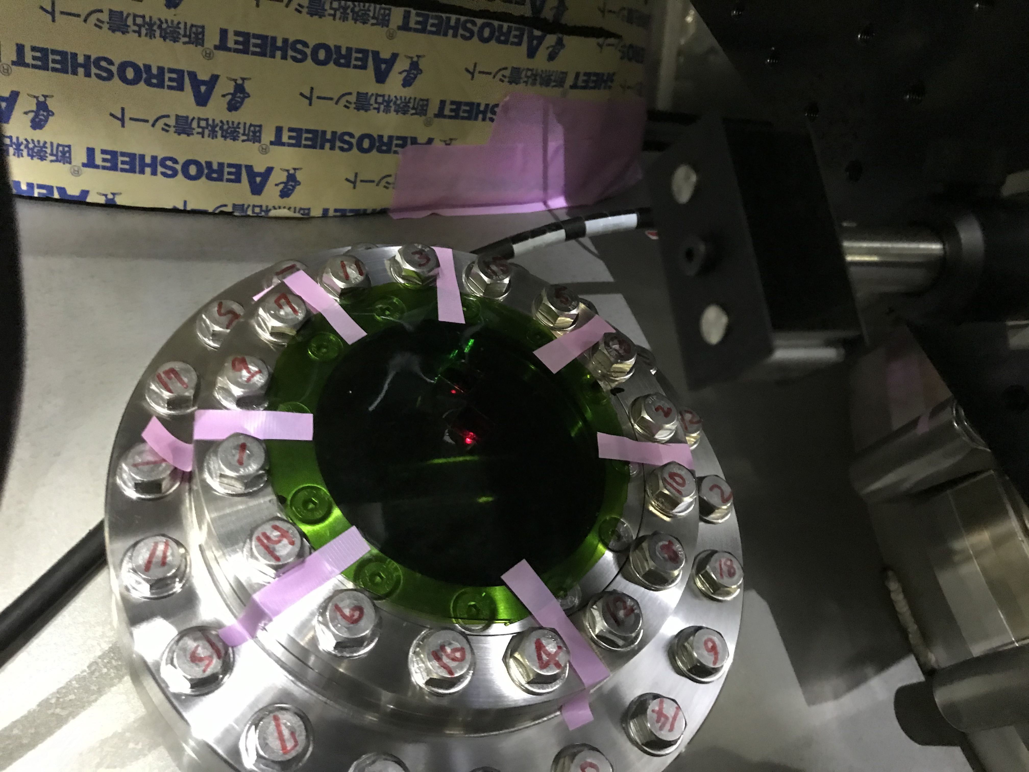
- To memorize where the oplev beam from the transmitter went, we put a manual iris diaphragm in front of the transmitter (Fig. 2). At the same time, to the oplev's viewport window, we applied a viewport cover with a small hole for the input oplev beam toward IMMT2. The hole's location was marked for easy identification (Fig. 1). The reason was that there was no other space for locating another iris on the optical table. Actually, to draw the mark and to make the hole, we once put the cover on the viewport frange, and marked the position at which the input beam hit, and detached the cover, and made the hole, then again attached the cover onto the frange to avoid danger of breaking the viewport window.
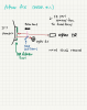
- Then, Miyoki-san, then, I moved slighty and slightly, gently, the transmitter without loosing the reflected beam. After moving the transmitter about 10 cm or so, we found that the reflection beam could pass thourght the edge of the transmitter's holder, so we fixed the transmitter there.
- But still it was difficult to put the QPD in fron of the transmitter. So we put the QPD behind the tansmitter. Due to this, a gap between the beam and the holder's edge was only 5mm or so. Let's see... One way to mitigate the tight gap would be to put another steering mirror for folding the reflection beam in the other direction and put the QPD there. Another way would be to put a wedged glass plate on the way of the reflected beam to somehow increase the amout of tilt, or in other words, increase the spacing between the reflected and input light beams. Actually, as mentioned later, we took the latter way "automatically", and hopefully this treatment would mitigate the tight situation...
- At this point, we checked whether the IR beam would affect the QPD or not by opening or closing the IR shutter; actually it did. So, we determined to do the IR treatment here.
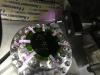
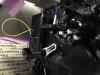
- We determined to do two things; (1) putting a color film on the frange of the viewport window (Fig. 4). The color film came out from Miyoki-san, and that was for flitering out IR light; it seemed deep green, so it might filter out also visible light, so we made two holes for the oplev's input and reflection beams. (2) At the same time, a 25mm-square KG5 glass was put in front of the QPD (Fig. 5). The glass was tilted to avoid multiple reflection of the beam between the glass and the QPD, and to make a slight shift of the beam to gain more space from the edge of transmitter's holder, as explained above.
- Put two beam dumps to dump some ghost beams of the oplev beam's wavelength.
- Of course, finally the QPD was centered with respect to the oplev beam.
Let's see...