CRY (Cryo-payload R&D)takafumi.ushiba - 12:56 Wednesday 09 July 2025 (34497)
Print this reportComment to Surface figure measurements for sapphire components (34489)
Thank you for measuring the surface of sapphire parts.
Is it possible to mask the edge of 1.5mm from the measurement results of HCB surface of sapphire ears? Our specification of the flatness for HCB surface is 77*27 area of 80*30 surface, so it would be helpful to compare the result with the data from the company.
VIS (General)takafumi.ushiba - 11:35 Wednesday 09 July 2025 (34495)
Print this reportCheck GAS output
I checked GAS filter output of all suspensions and found that PR3 SF GAS and SRM F1 GAS is close to the saturation. Figure 1 shows the GAS filter output at IOP models (left:PR3 SF, right:SRM F1).
In addition, ITMY GAS output is also close to the limit (output is more than 85% of ful range, fig2). So, it would be better to offload them in the next maintainance day.
Images attached to this report
Comments to this report:
hirotaka.yuzurihara - 11:54 Wednesday 09 July 2025 (34496)
Print this report
OBS (General)takafumi.ushiba - 10:53 Wednesday 09 July 2025 (34494)
Print this reportComment to Set observing bit (34099)
We turned off the OBS INTENT around 9:09 JST and on it around 10:49 JST for SR3 GAS offload work (klog34492).
OBS (SDF)ryutaro.takahashi - 10:08 Wednesday 09 July 2025 (34493)
Print this reportComment to Changes of observation.snap during O4c (34169)
I accepted the following difference of SDFs (see related klog34492)
Images attached to this comment
VIS (SR3)ryutaro.takahashi - 10:05 Wednesday 09 July 2025 (34492)
Print this reportComment to F1 GAS is saturated again (34484)
I offloaded the F1 GAS with the standalone FR.
CRY (Cryo-payload R&D)dan.chen - 9:49 Wednesday 09 July 2025 (34491)
Print this reportComment to Surface figure measurements for sapphire components (34489)
We also used 2 microscopes to have a look on the surface of the blade.
Keyence VR3200
Nikon NM-40
I attached the pictures taken by the microscopes.
What we saw
Numerous linear scratches were observed on the surface. These are clearly visible even to the naked eye.
The sloped edges around the hole are noticeably rough.
The rim of the hole appears jagged
Images attached to this comment
MIF (General)shinji.miyoki - 22:14 Tuesday 08 July 2025 (34490)
Print this reportComment to BNS vs IR Trans Norm (34435)
I just compared BNS and IR/GR XY trans Norm for the recent 22 days as Fig.1.
GRX is almost constant except for a slight drop at some point, while GRY increased at some point and has remained almost constant. On the other hand, IRXY keeps decreasing. The relative alignment for IR and GR is now aparting with each other?
Images attached to this comment
CRY (Cryo-payload R&D)dan.chen - 20:09 Tuesday 08 July 2025 (34489)
Print this reportSurface figure measurements for sapphire components
With Yoich Aso and Toshihiro Tsuzuki (NAOJ ATC)
We measured surface figures of a sapphire ear (made by K), a nail head (made by S) and blade spring (made by S).
Measured surface:
Sapphire ear
Surface for HCB (figure 1, 2: upside down)
Surface for Ga bonding (figure 3)
Sapphire nail head
Surface for Ga (A) (figure 4)
Surface for Ga (B) (figure 5)
(We can not distinguish A and B)
Sapphire blade spring
Top surface (figure 6,7)
Bottom surface (figure 8,9)
(We could not distinguish top and bottom at the measurement time.)
(Side surfaces could not be measured)
I attached quick results.
Images attached to this report
Comments to this report:
dan.chen - 9:49 Wednesday 09 July 2025 (34491)
Print this report
We also used 2 microscopes to have a look on the surface of the blade.
Keyence VR3200
Nikon NM-40
I attached the pictures taken by the microscopes.
What we saw
Numerous linear scratches were observed on the surface. These are clearly visible even to the naked eye.
The sloped edges around the hole are noticeably rough.
The rim of the hole appears jagged
Images attached to this comment
takafumi.ushiba - 12:56 Wednesday 09 July 2025 (34497)
Print this report
Thank you for measuring the surface of sapphire parts.
Is it possible to mask the edge of 1.5mm from the measurement results of HCB surface of sapphire ears? Our specification of the flatness for HCB surface is 77*27 area of 80*30 surface, so it would be helpful to compare the result with the data from the company.
VAC: No issues were found. CRY cooler: No issues were found. Compressor: No issues were found.
IFO state (JST): 09:00 The shift was started. The status was OBSERVING. 10:12 Lockloss with AS_0CROSS label 10:38 OBSERVING 11:06 Large earthquake arrived, Lockloss 11:39 OBSERVING 17:00 This shift was finished. The status was OBSERVING.
OBS (General)shoichi.oshino - 14:30 Tuesday 08 July 2025 (34487)
Print this reportAdded new script to calculate difference of each booth temperatureI added new script to calculate difference of each booth temperature. You can use this script from the operator medm screen.
Images attached to this report
MIF (General)takaaki.yokozawa - 13:32 Tuesday 08 July 2025 (34486)
Print this reportComment to Memo250707 (34478)No coherence with PR3 OLDAMP Y. (PR3 fluctuation was lower than the oplev noise or didn't move.)
Images attached to this comment
OBS (General)shoichi.oshino - 11:02 Tuesday 08 July 2025 (34485)
Print this reportAdded button to open operator shift MEDM screenI added button to open operator shift MEDM screen from the sitemap.
Images attached to this report
VIS (SR3)takahiro.yamamoto - 9:46 Tuesday 08 July 2025 (34484)
Print this reportF1 GAS is saturated again
F1 GAS of SR3 is now being saturated (previous saturation was reported in klog#34102). TPs of 2kHz and 65kHz are shown in Fig.1. Saturation is still caused only in high frequency due to the up-sampling process.
Figure 2 shows the 1-month trend of GAS output and temperature around SR3. Slightly higher temperature (same as around 25 days ago) seems to be better for F1 GAS output. Anyway, it's better to do the offload work (by height adjustment or temperature adjustment?) to remove DAC saturation.
Images attached to this report
Comments to this report:
ryutaro.takahashi - 10:05 Wednesday 09 July 2025 (34492)
Print this report
I offloaded the F1 GAS with the standalone FR.
MIF (General)takaaki.yokozawa - 8:44 Tuesday 08 July 2025 (34483)
Print this reportComment to Memo250707 (34478)Both after the locked loss and increasing laser power, the SUM of the PR3 tilt and len QPD was not changed, so the effect of IR to PR3 oplev can be negligible.
Images attached to this comment
MIF (General)dan.chen - 7:53 Tuesday 08 July 2025 (34482)
Print this reportComment to Violin mode Q estimation (34436)
IM temperatures during GPS time = 1435056520s - 1435096620s
VAC: No issues were found. CRY cooler: No issues were found. Compressor: No issues were found.
IFO state (JST): 09:00 The shift was started. The status was OBSERVING. 12:07 Large earthquake arrived, Lockloss 12:46 OBSERVING 17:00 This shift was finished. The status was OBSERVING.
Since current PRC2 ASC signals are fedback to the setpoint of PR3 OpLevs, the effect of WFS signals through the feedback is smaller than that of OpLev signals. So, if ASC signals contaminates DARM, it should be also seen in PR3 OpLev signals.
I don't think OpLev feedback affects at such high frequency but could you check the signals?
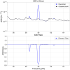
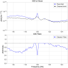
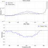
MIF (General)takaaki.yokozawa - 15:27 Monday 07 July 2025 (34478)
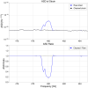
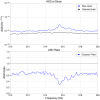
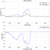
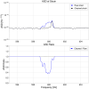
Print this reportMemo250707In this morning, I noticed that the detection range was different about 1 Mpc even the ground motion (Human retion 1 - 3 Hz) level was almost similar (as shown in Fig.1.) As you can see, the shape of 60 - 110 Hz was similar in (blue) 10:30 and (red) 13:10, but floor level increasing. If we can find this issue, we may obtain the hint for next step
Fig.2. showed the coherence between DARM and feedback signal to PR3 yaw. In current ASC, PR3 yaw signal can be obtained from WFS REFL 45 I. As shown in klog34400, there are several coherence in 115 Hz 140 Hz and 160 Hz in PDA45I (and 45Q). If we perform the reshaping of ASC filter for the PRC2, there are possibility to reduce the peaks (or > 100Hz feedback would be too low to fluctuate the PR3 mirror?)
Images attached to this report
Comments to this report:
takafumi.ushiba - 16:46 Monday 07 July 2025 (34479)
Print this report
Yokozawa-san,
Since current PRC2 ASC signals are fedback to the setpoint of PR3 OpLevs, the effect of WFS signals through the feedback is smaller than that of OpLev signals. So, if ASC signals contaminates DARM, it should be also seen in PR3 OpLev signals.
I don't think OpLev feedback affects at such high frequency but could you check the signals?
tomotada.akutsu - 19:18 Monday 07 July 2025 (34481)
Print this report
Apart from the control bandwidth. Does PR3 oplev QPDs have IR filters set?? If no, it might be contamination from the main IR scattered light.
takaaki.yokozawa - 8:44 Tuesday 08 July 2025 (34483)
Print this reportBoth after the locked loss and increasing laser power, the SUM of the PR3 tilt and len QPD was not changed, so the effect of IR to PR3 oplev can be negligible.
Images attached to this comment
takaaki.yokozawa - 13:32 Tuesday 08 July 2025 (34486)
Print this reportNo coherence with PR3 OLDAMP Y. (PR3 fluctuation was lower than the oplev noise or didn't move.)
Images attached to this comment
DMG (Data transfer & archiving)takahiro.sawada - 18:01 Sunday 06 July 2025 (34477)
Print this reportComment to Data transfer during network disconnection (34440)We regenerated the 4096-second segment of LL h(t) over the GPS time interval [1435459584, 1435463680), which includes the missing period [1435460351, 1435461886).
MIF (General)dan.chen - 17:24 Sunday 06 July 2025 (34476)
Print this reportComment to Violin mode Q estimation (34436)
I used longer data to estimate the Q value of the violin modes. This time I could set 4096s as the fft length. Used data: GPS time = 1435056520s - 1435096620s
The results were obtained as follows:
The fitting performed better than before, primarily because more data points around the peaks could be used for fitting.
No peaks showed unreasonably large Q-values.
Most of the peaks have Q-values around 10^5.
A figure summarizing the fitting results for all peaks is attached. Peaks marked with an "X" indicate cases where the number of available data points was small or where the fitting clearly did not fit well.
All fitting results have been uploaded to Dropbox: link
Images attached to this comment
OBS (Summary)hiromi.yasui - 17:15 Sunday 06 July 2025 (34475)
Print this reportOperation Shift Summary
Operators name: Tamaki, Yasui
Shift time: 9:00-17:00 (JST)
Check items:
CRY: The temperature of EX_REFBRT_HEAD was rapidly increased. Consequently, the temperatures of REFBRT_BAR, BRT1 and BRT2 also started increasing, and BRT3 and BRT4 are expected to follow.
(According to the manual, we reported this issue to Ushiba-san and Kimura-san after the regular check at 10:00 and 16:00, because we observed a temperature increase of more than 10 K compared to the previous values.)
VAC: The pressure values of TMSX and EXC slightly increased due to the temperature rise mentioned above, but this is not caused by H2O.
TEMP: There was no issue.
IFO state (JST):
9:00 OBSERVING
12:50 LOCKLOSS due to the earthquake
13:16 OBSERVING
13:26 LOCKLOSS due to the earthquake
13:58 OBSERVING
14:06 LOCKLOSS due to the earthquake
15:13 OBSERVING
17:00 OBSERVING
Images attached to this report
MIF (General)Shu-Wei Yeh - 2:54 Sunday 06 July 2025 (34474)
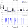
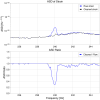
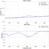
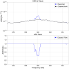
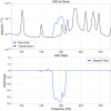
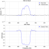
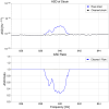
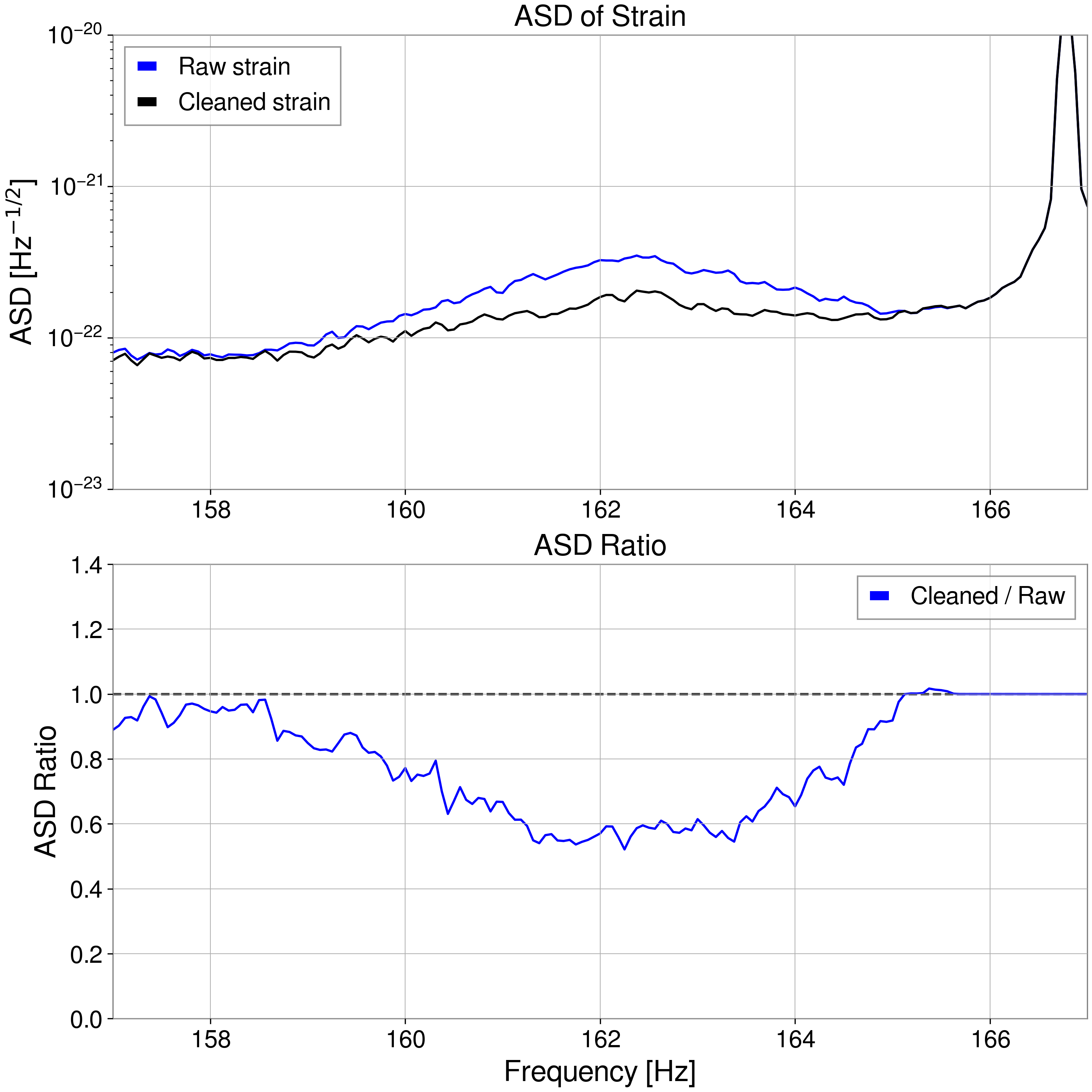
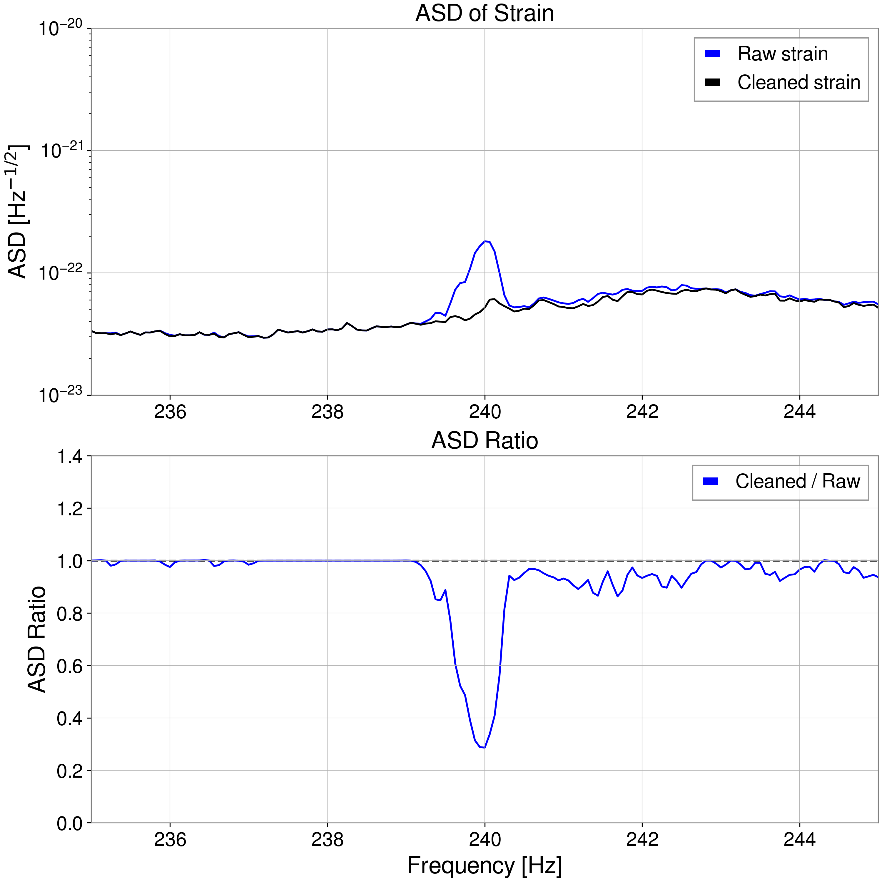
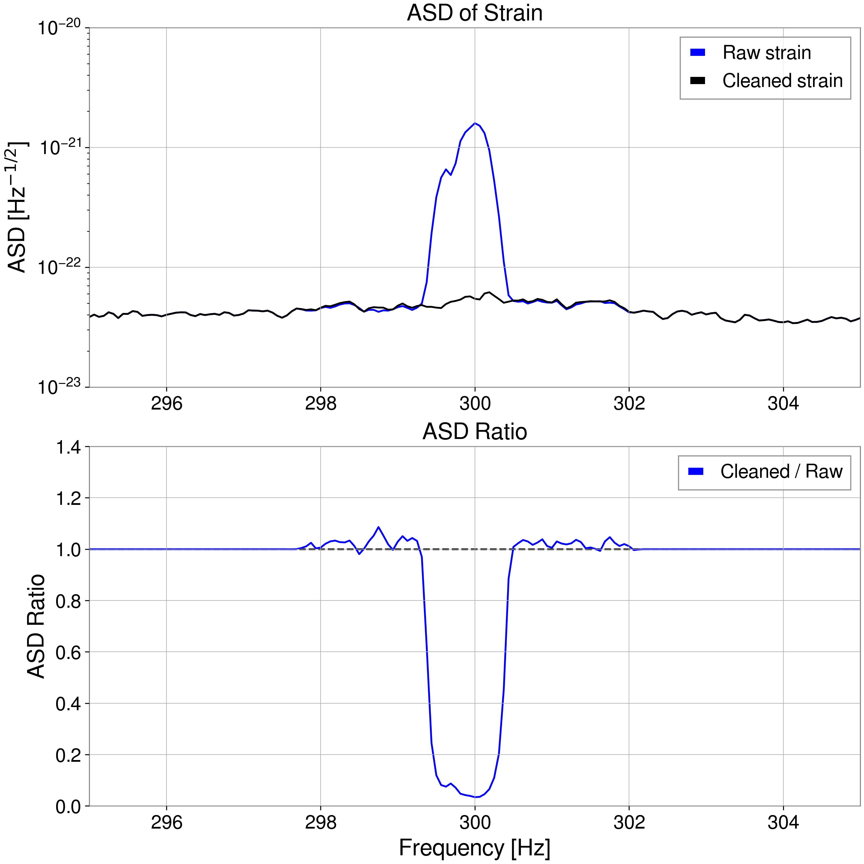
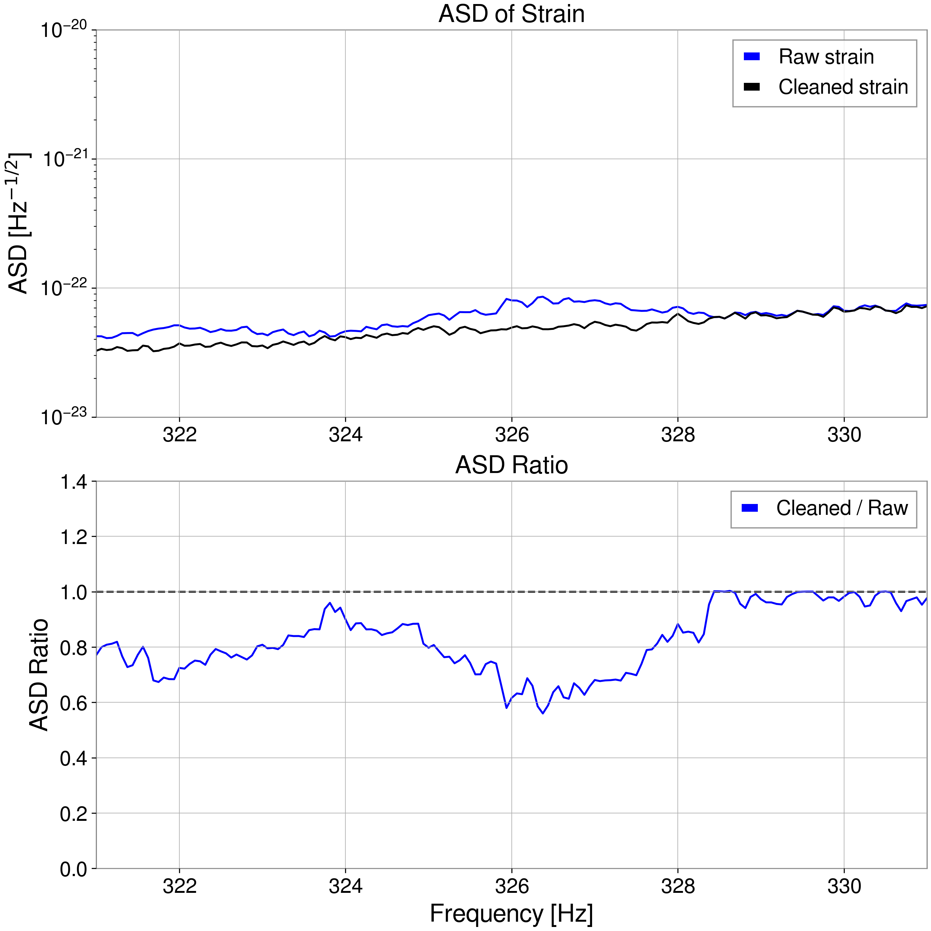
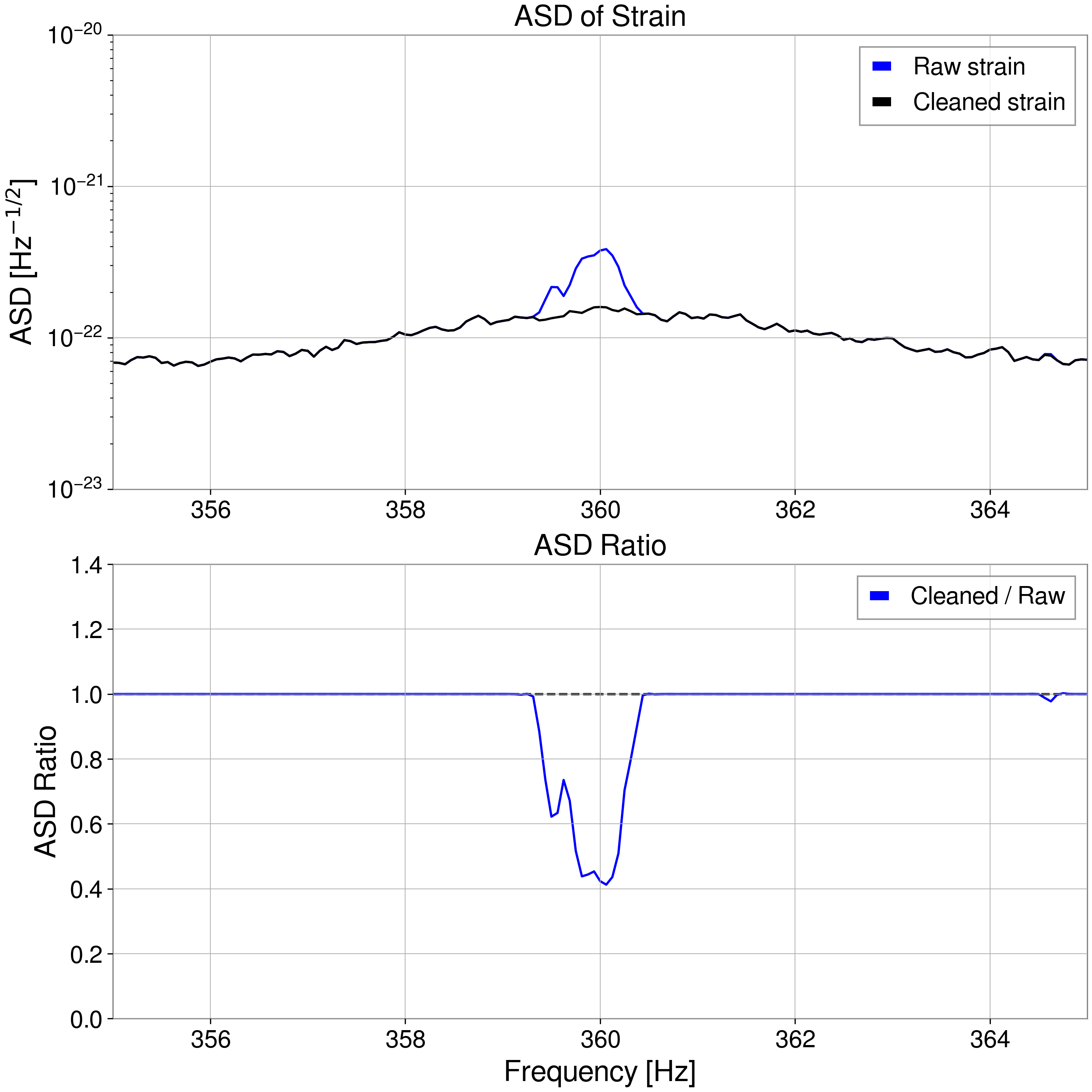
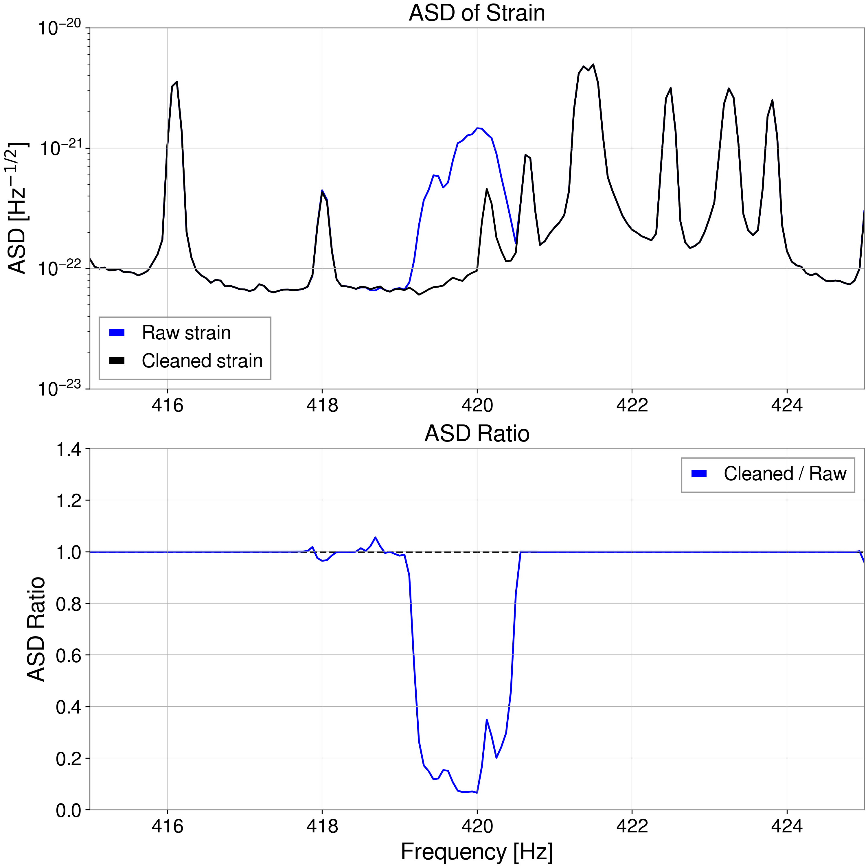
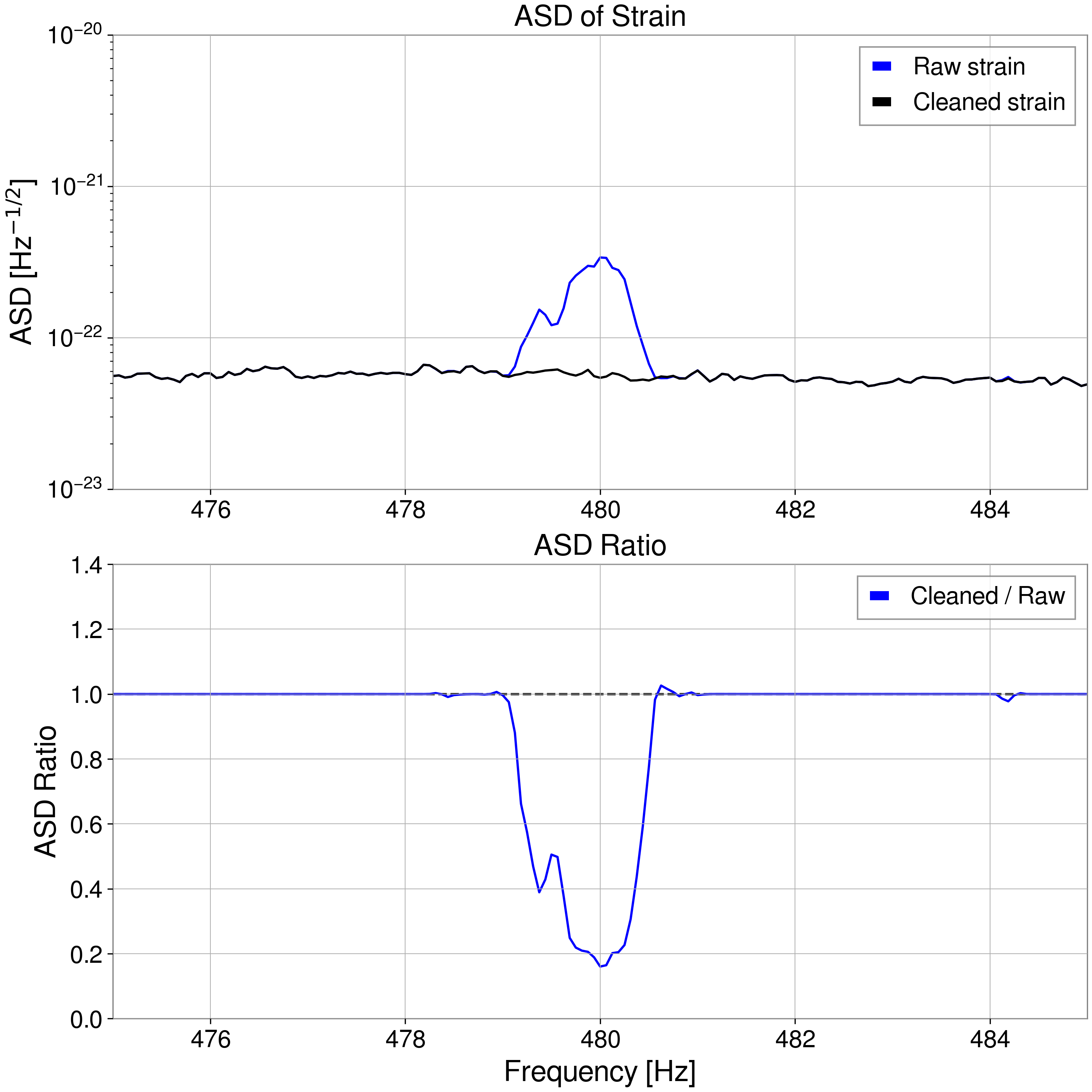
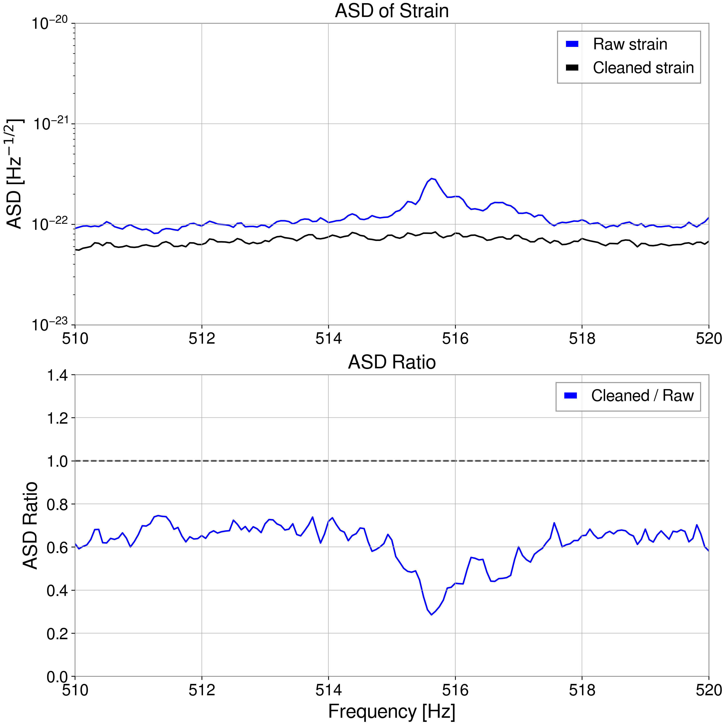
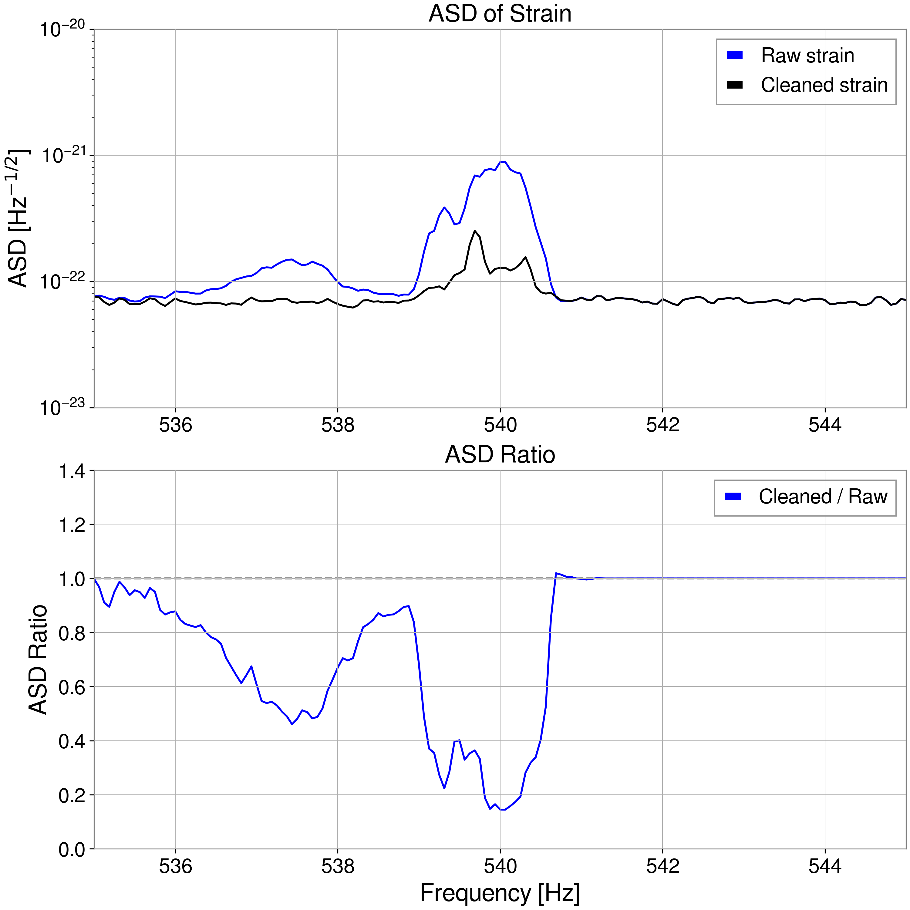
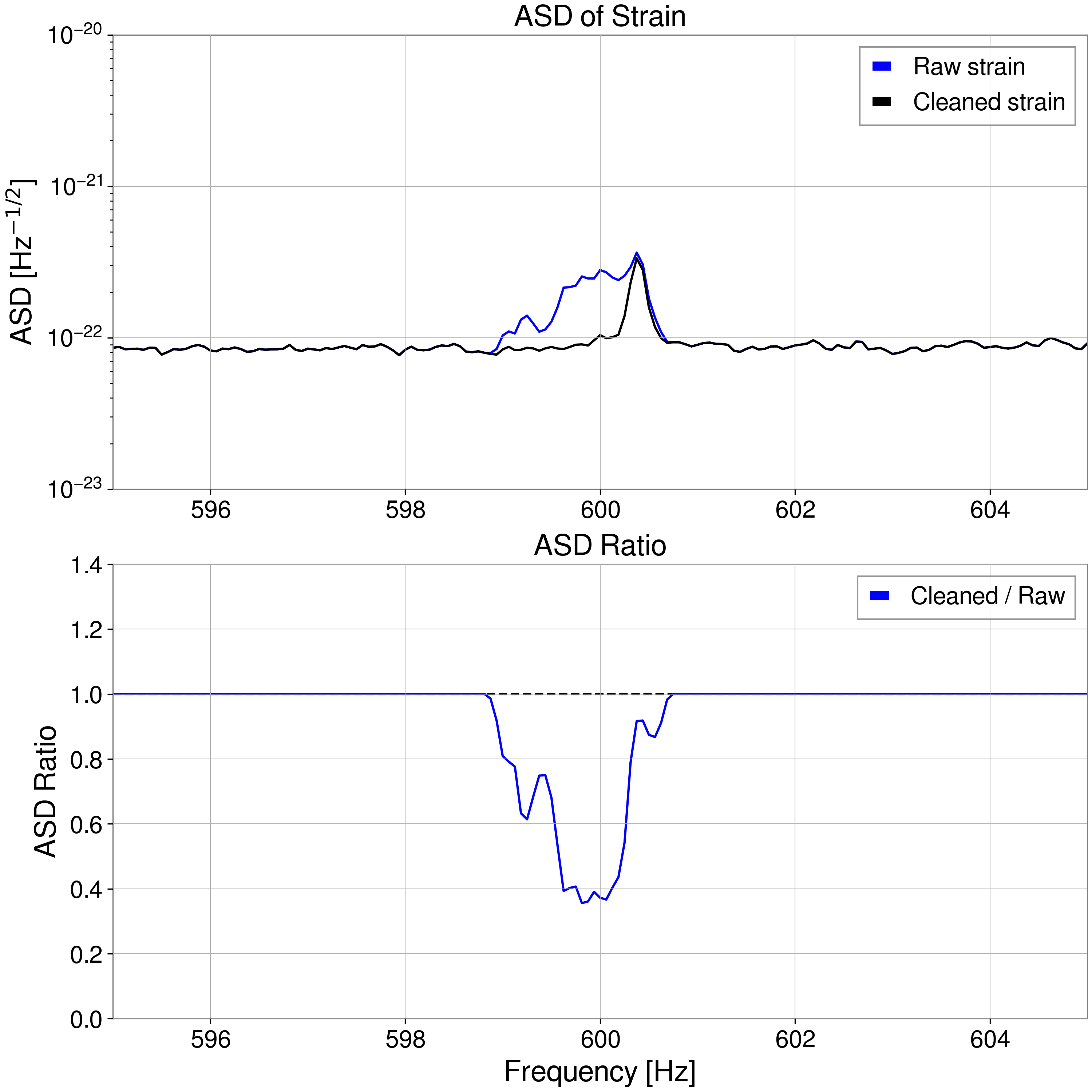
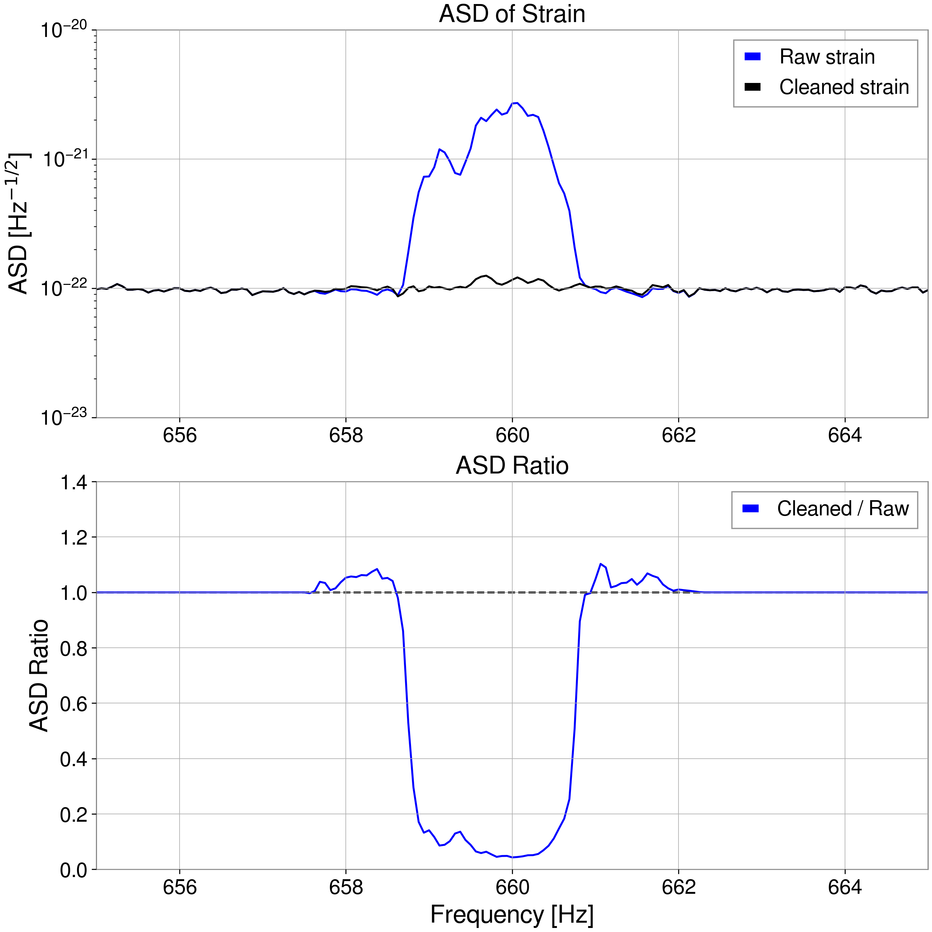
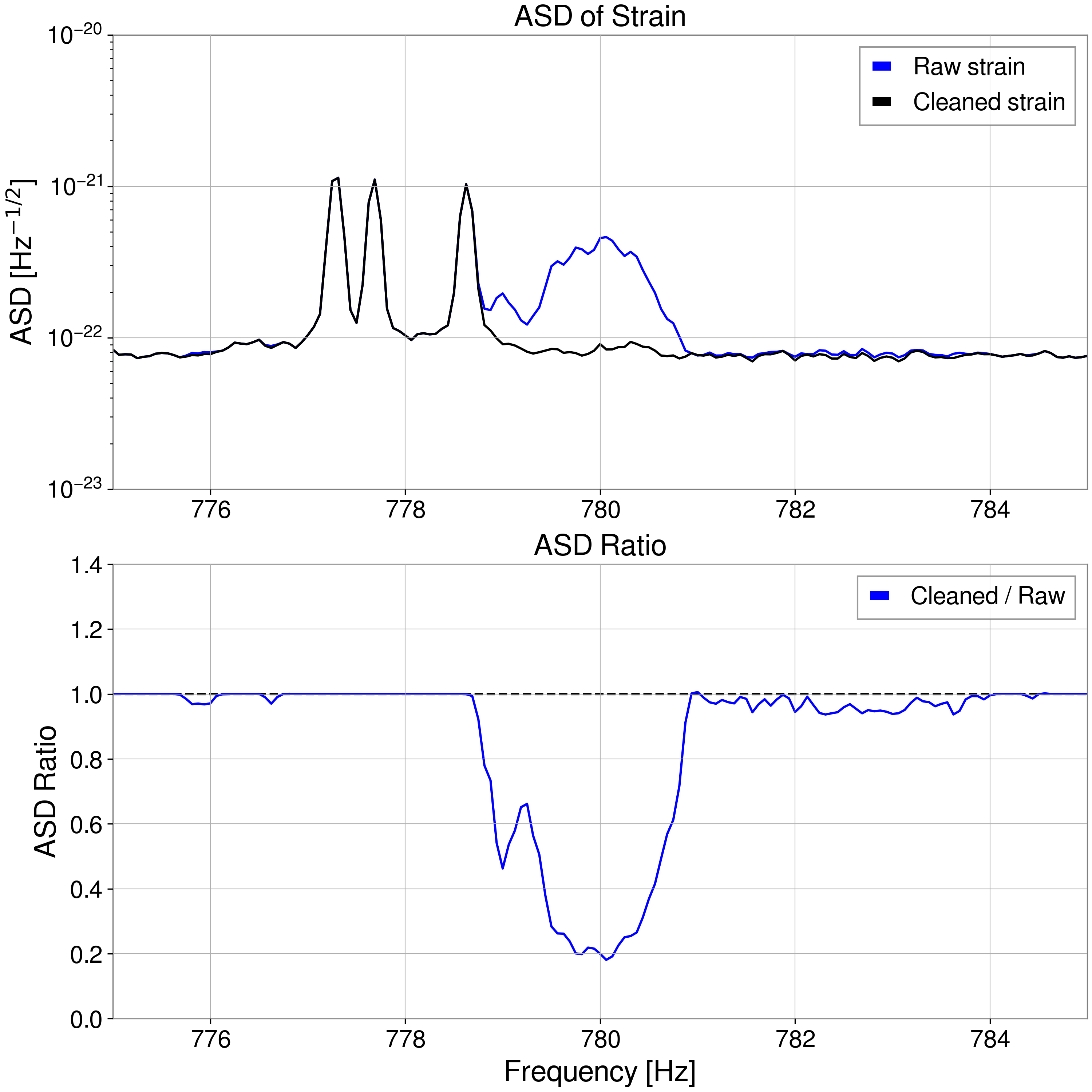
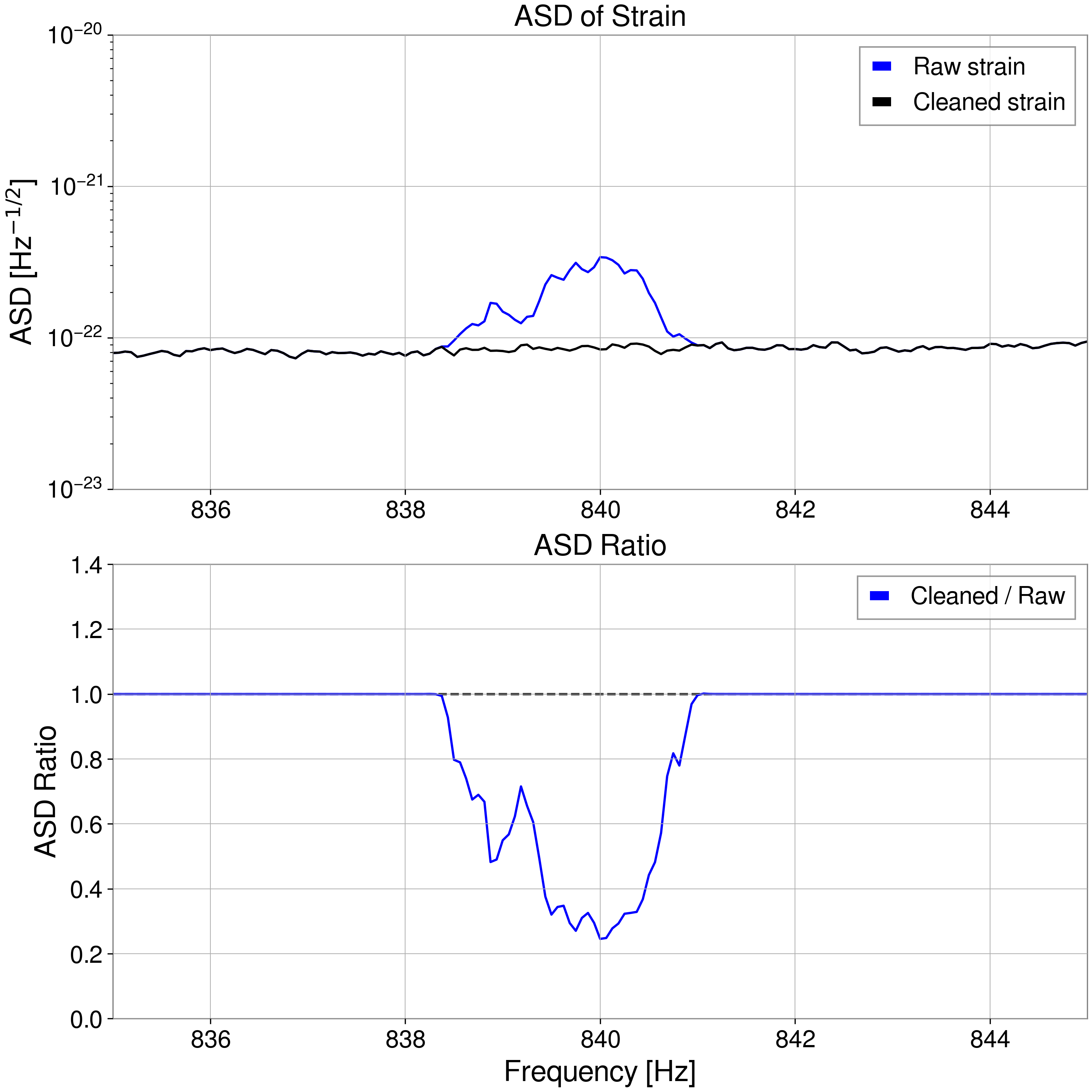
Print this reportNoise Subtraction from KAGRA O4c Data Using ICA
[Shu-Wei Yeh, Chia-Jui Chou]
We applied ICA to clean KAGRA strain data from 1435106958 to 1435111758 (00:49–02:09 UTC, June 28, 2025) [Ref. klog 34400], using a cleaning duration of 1200 seconds. The segment was divided into four intervals for testing noise subtraction: 1435106958, 1435108158, 1435109358, and 1435110558. Here, we present the results for the interval starting at 1435108158.
The central frequencies (f_c), step-by-step improvements, and the overall inspiral range improvement are listed below. We observed effective noise subtraction in the June 28 data.
For the remaining denoising results and the list of witness channels used, please refer to the attached slides here, JGW-G2516738-v2.
The next step is testing DeepClean's performance on the June 28 data.
f_c [Hz]
Incremental (per-band) improvement [%]
Cumulative improvement [%]
60
0.139
0.139
120
0.444
0.583
162
0.263
0.847
240
0.118
0.966
300
0.027
0.994
326
0.247
1.243
360
0.002
1.245
420
0.004
1.250
480
0.009
1.259
515
0.073
1.333
540
0.010
1.343
600
0.001
1.344
660
0.001
1.346
780
0.002
1.348
840
0.001
1.348
Images attached to this report
OBS (Summary)hiromi.yasui - 17:16 Saturday 05 July 2025 (34473)
Print this reportOperation Shift Summary
Operators: Hido, Yasui
Shift time: 9:00-17:00 JST
Check Items: There was no issue on the regular check of VAC, CRY, and TEMP.
(Ikeda-san’s script for comparing cryocooler temperatures was very helpful!)
IFO state (JST):
9:00 OBSERVING
12:33 LOCKLOSS
(While recovering the IFO, there was an earthquake near the Tokara Islands around 12:50.)


