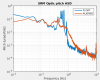
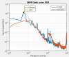
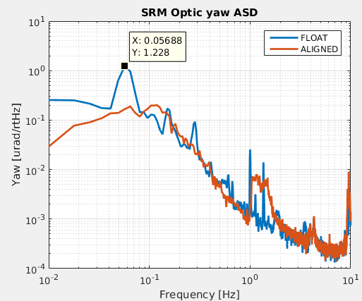
Yesterda I measured the residual motion of the optic in ALIGNED and FLOAT states.
In the ALIGNED state the optic RMS displacment and velocity fulfills the requirement. However, in the FLOAT state the longitudinal displacement is higher than the requirement. We should check the origin of the excess displacement and mitigate it, especially because other Type B suspensions fulfill the requirement in FLOAT state. It's worth mentioning the main interferometer team wants to have some sort of local control system for the payload during observation time, but the details still have to be decided.
This table shows the integrated RMS displacement for each degree of freedom and the requirement.
| Degree of freedom | ALIGNED | FLOAT | Requirement |
| Longitudinal displacement | 0.16 µm | 0.44 µm | 0.4 µm |
| Longitudinal velocity | 0.21 µm/s | 0.23 µm/s | 0.5 µm/s |
| Pitch displacement | 0.047 µrad | 0.12 µrad | 1 µrad |
| Yaw displacement | 0.060 µrad | 0.16 µrad | 1 µrad |
Notes:
- There is no inertial damping.
- Directory: /kagra/Dropbox/Subsystems/VIS/TypeBData/SRM/Noise/Measurements/20190730/
- File for ALIGNED state: SRM_ALIGNED_TM_OPLEV_ASD_190730_1564467591.xml
- File for FLOAT state: SRM_FLOAT_TM_OPLEV_ASD_190730_1564468621.xml
- Bandwidth of the displacement measurement' from 0.010 Hz to 800 Hz.
- The bandwidth of the optic velocity measurement was from 0.010 Hz to 10 Hz. Above 10 Hz there is a lot of noise which I don't believe is real displacement of the optic. The peaks are likely related to the oplev optics support platform
- Related entries: 8945, 9456., 9697, 9702, 9703.