Reports 1-1 of 1 Clear search Modify search
MIF (General)
kazuya.yokogawa - 22:51 Friday 14 December 2018 (7404) Print this report
Set up for ALSY system

[Izumi, Sugimoto, Yokogawa]

We proceeded with the preparation for the ALS Y arm system.


1. Installation of the optical fiber for ALSY

Related log about fiber installation:

  • Aug. 10th 2018 (log5774): The optical fiber was delivered and the fiber transmittance was measured.
  • Aug. 11th 2018 (log5785): The delivered fiber was laid by Fujitsu Fsas and the fiber transmittance was measured after fiber laying.

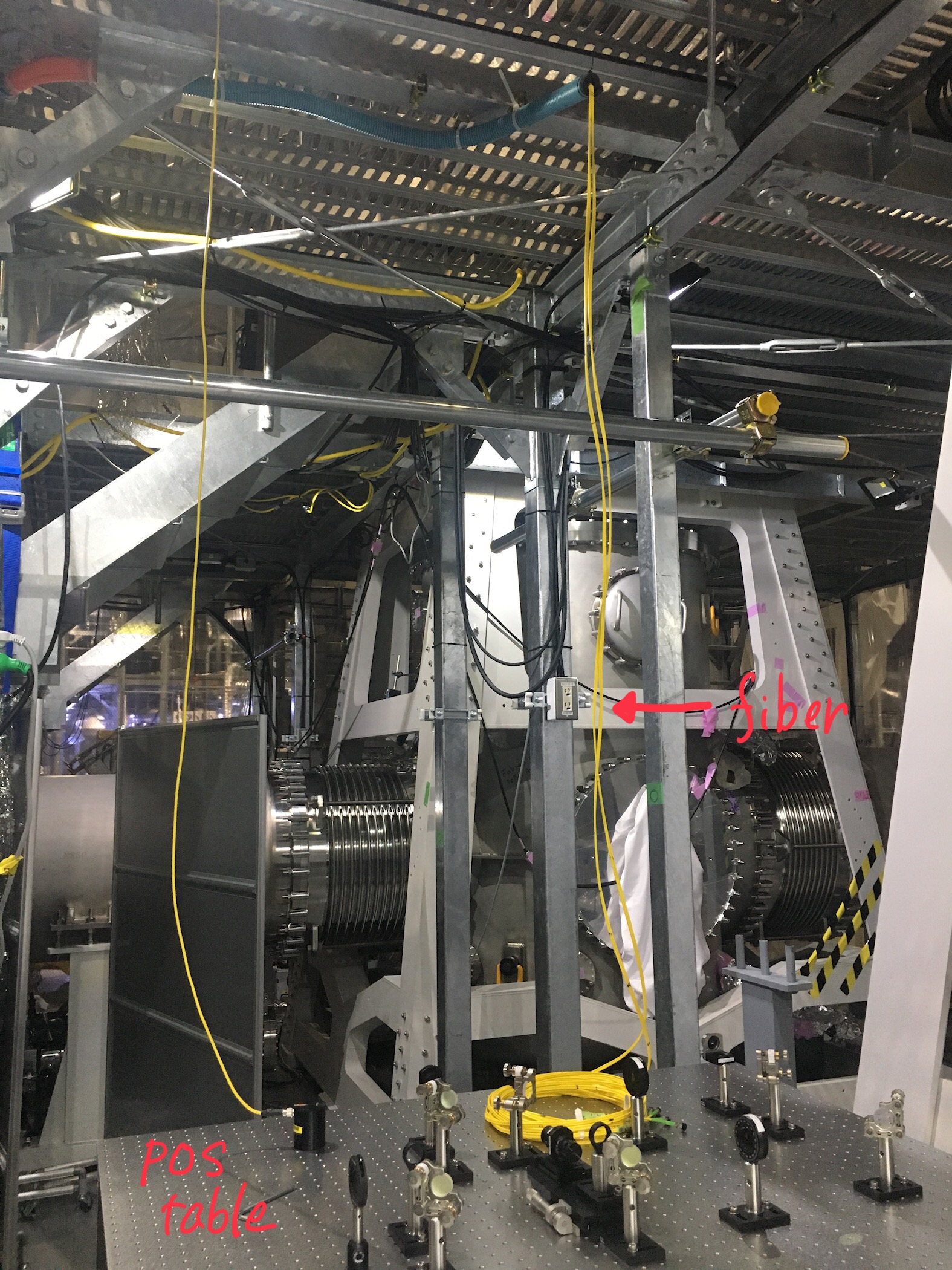
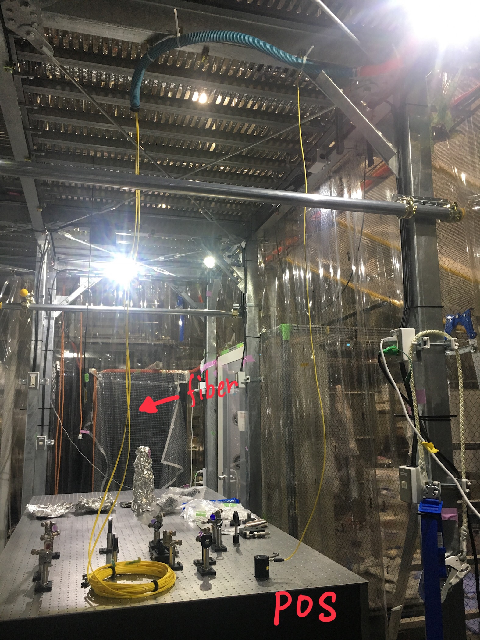
The optical fiber which transmit green beam for ALSY system from the PSL table to the POS table was laid to aroud the POP table and the rest of the fiber was rolled and placed on the LSC rack beacause the POS table had not been installed when the optical fiber was laid by Fujitsu Fsas. Since the POS table was installed on Nov. 9th (log6930), we laid the rest of the fiber to the POS table today.

What we did:

  1. covered the rest of the fiber using blue flexible tube.
  2. protected the fiber near the entrance and exit of the blue flexible tube using low-resistance cushioning materials.
  3. fixed the flexible tube to the I-shape pillar supporting the 2nd floor with C-shape clamp.
  4. installed a pillar post as a guide of the fiber from the top to the surface of the POS table.
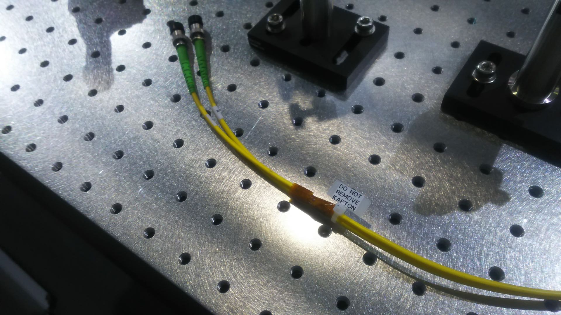
  5. fixed fibers on the table using masking tape.

(I forgot to take pictures after the work of numbers 4 and 5.)


2. Setup of ALSY optics on the PSL table

Yesterday, the new PROMETHEUS laser was installed (log7384), so we aligned optics for ALSY system on the PSL table. Current status is following.

Green path: All the optics except the fiber coupler was aligned. It is necessary to bring the fiber coupler stored at Univ. of Toyama.

IR path: All the optics have not been aligned yet.

Images attached to this report
Comments to this report:
kiwamu.izumi - 3:00 Thursday 20 December 2018 (7454) Print this report

Kazuya, Ryousuke, Kiwamu,

--- An addendum.

We learned that there was a portion where the fibers were not covered by the yellow jacket under the black tubing presumably at each end of the duplex fiber.

The message here is that one can easily put himself or herself into a sad situation where the fiber is unintentionally damaged when he or she tries to remove a black tubing because of the facts that the black tubings are not easy to remove and the fibers are exposed under the tubings. So don't remove them unless you have a good reason to do it.

Since we didn't know this fact, we actually almost removed the black tubing at the end of the duplex green fiber on the POS table. We originally thought that removing the black tubing would enable us to further split the two fibers so that one can separately isolate them from some vibration in easier fashion. The black tubing seemed to have been glued on to the yellow jacket. So we used a wire cutter to carefully take the tubing off without damaging the fibers. Then realizing that a few mm long portion of the fibers were exposed out of the yellow jacket, we stopped removing it and subsequently re-wrapped the black tubings with the aid of Kapton tapes around it. See the first attachment for a picture of the fiber end that is now taped by Kapton. As seen in the picture, we also put a small caution label so that no one will remove the tubings in future.

After this, we additionally made sure that both A and B fibers can still transmit some light using a fiber checker which emits red-ish visible light.

kiwamu.izumi - 17:06 Thursday 20 December 2018 (7464) Print this report

For some reason, the picture that I attached disappeared. Hence this log with the same attachment.

Images attached to this comment
Search Help
×

Warning

×