Reports 1-1 of 1 Clear search Modify search
VIS (PR3)
fabian.arellano - 20:36 Tuesday 02 February 2021 (15889) Print this report
Traverser motor test and cabling.

With Hirata-san and Ikeda-san.

See pictures in album PR3 Remedying Work.

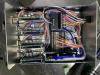
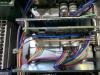
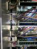
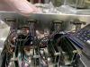
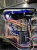
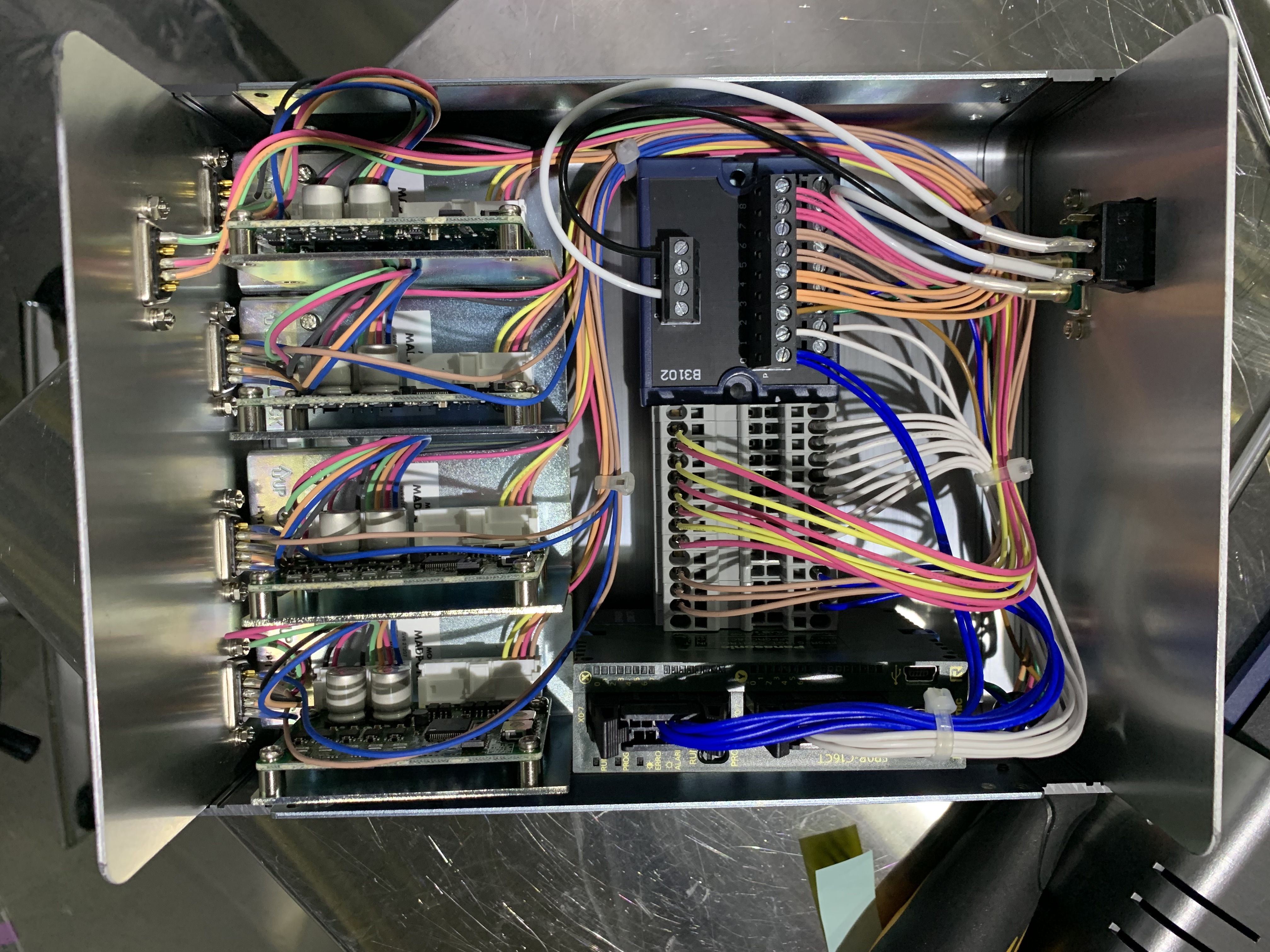
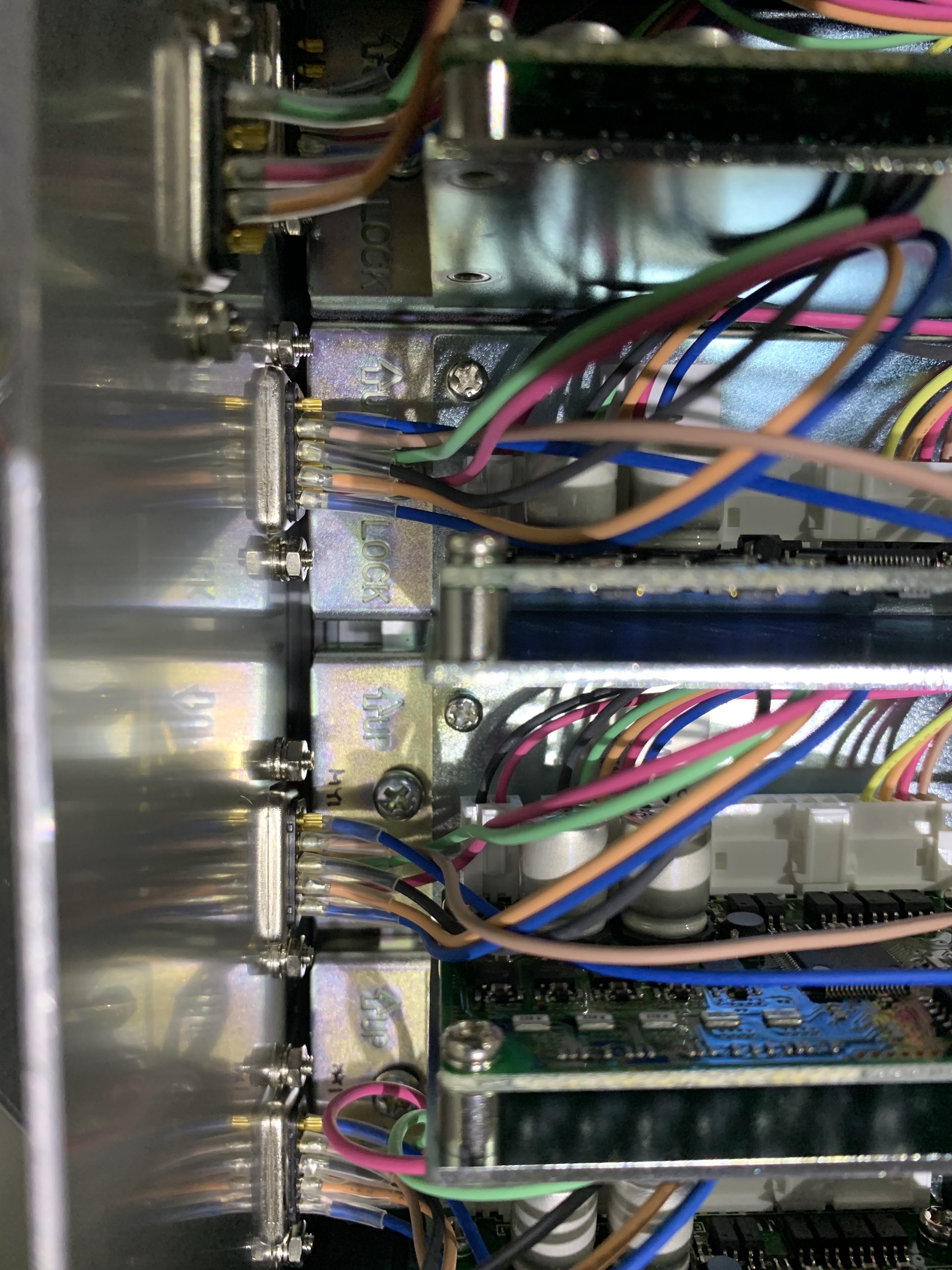
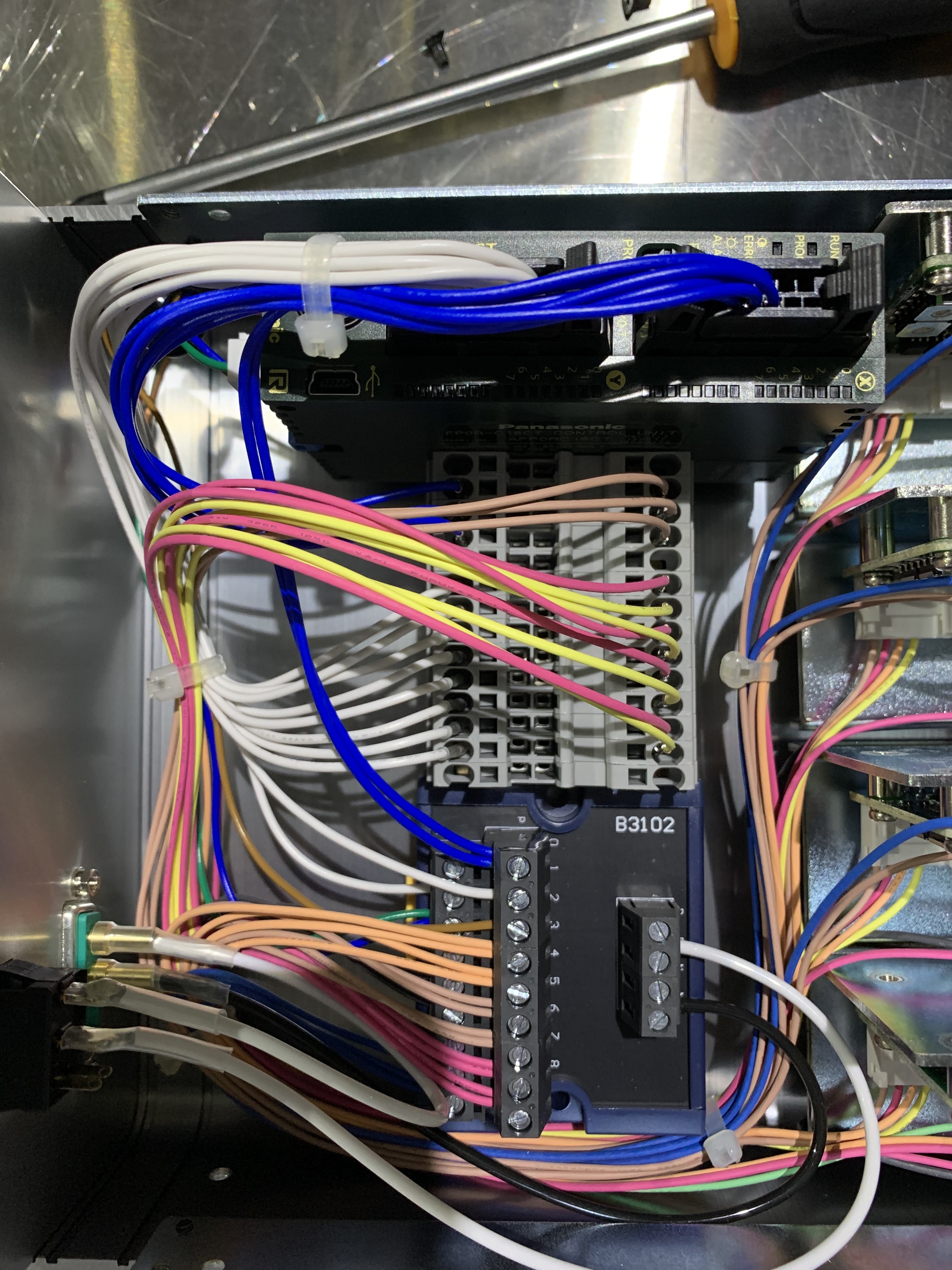
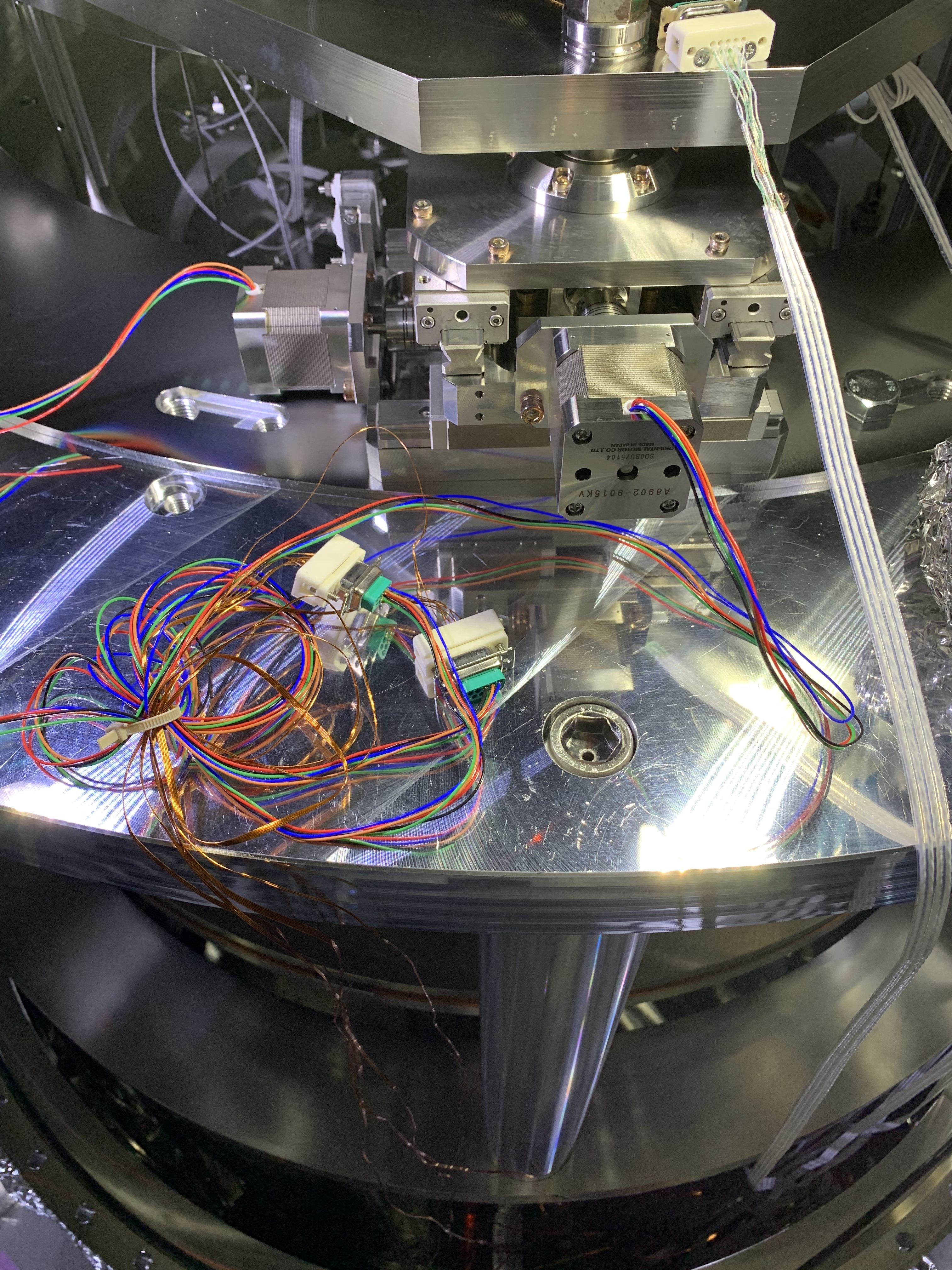
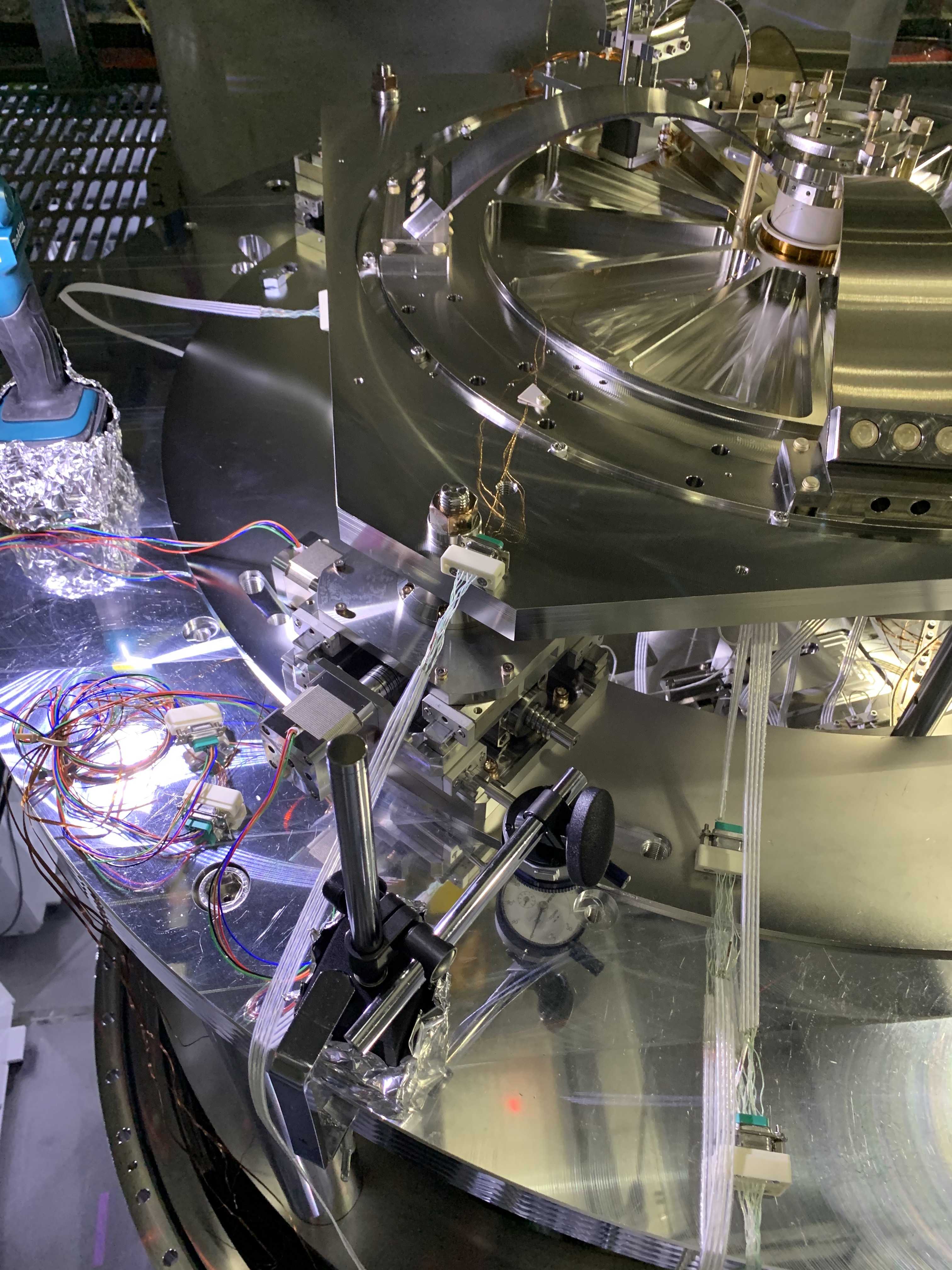
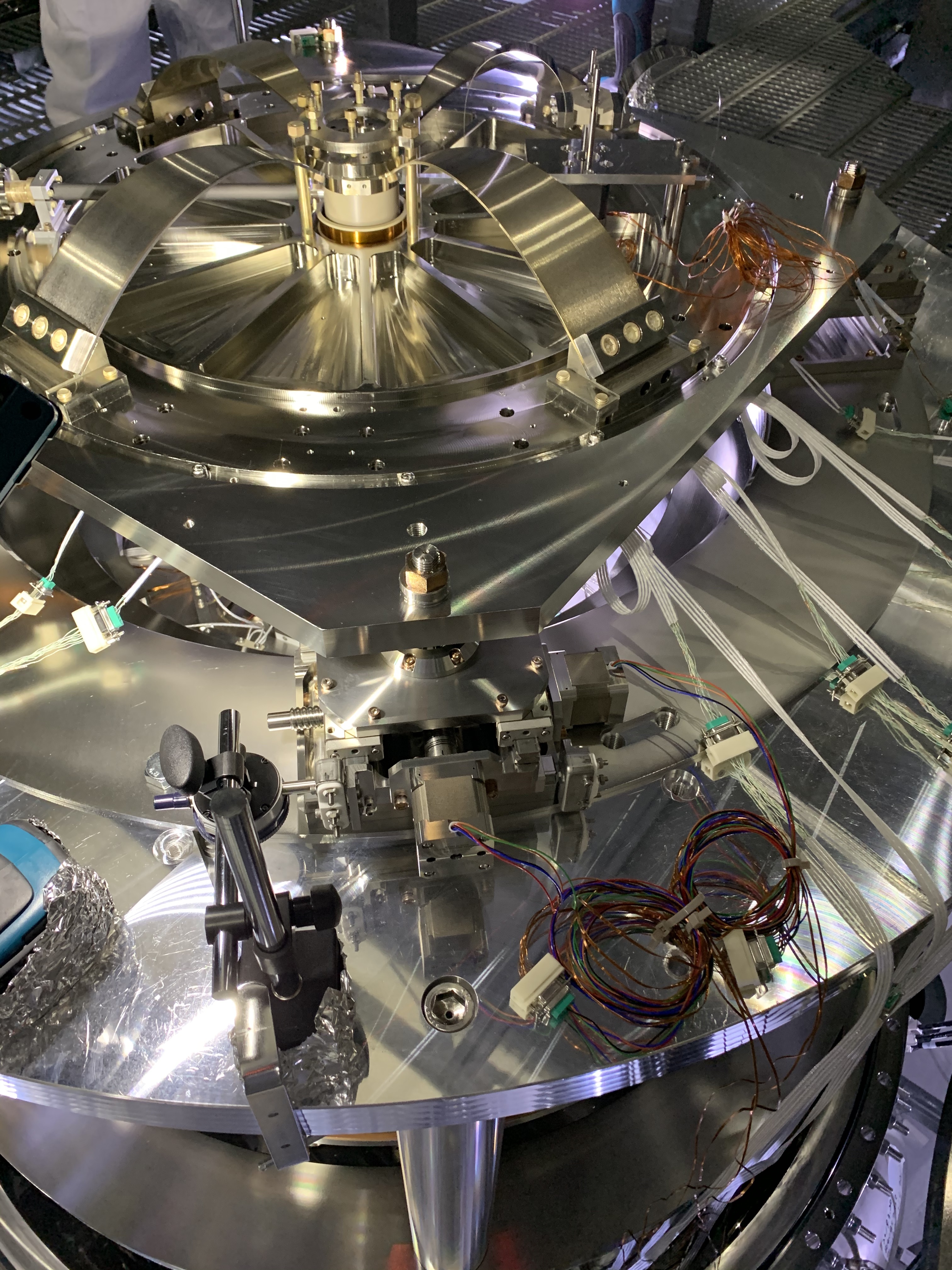
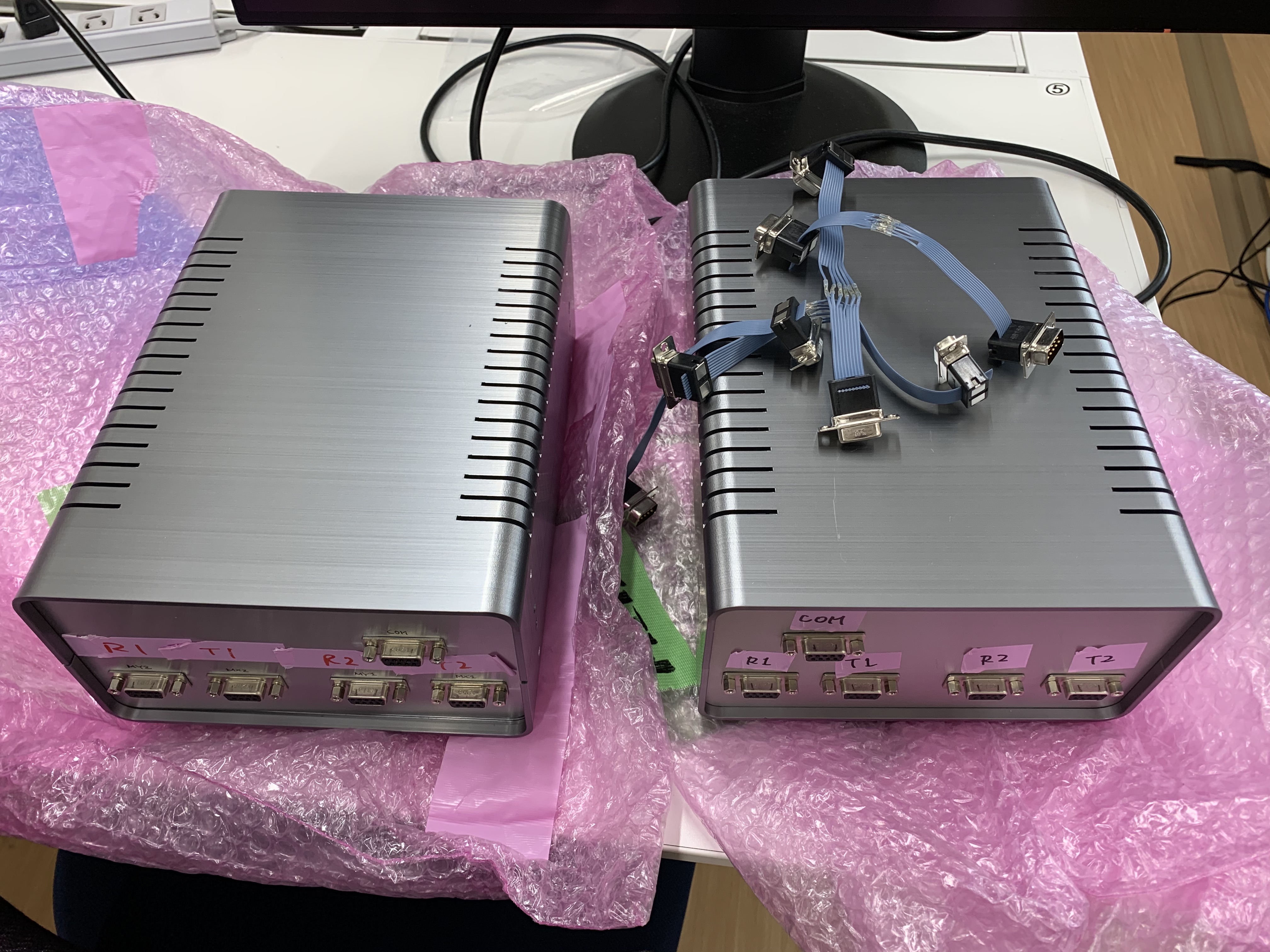
Today we aimed to test the traverser system, which includes the cabling, the driver and the script. 

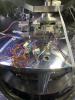
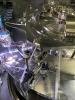
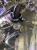
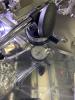
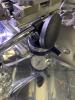
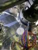
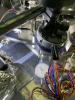
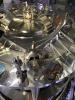
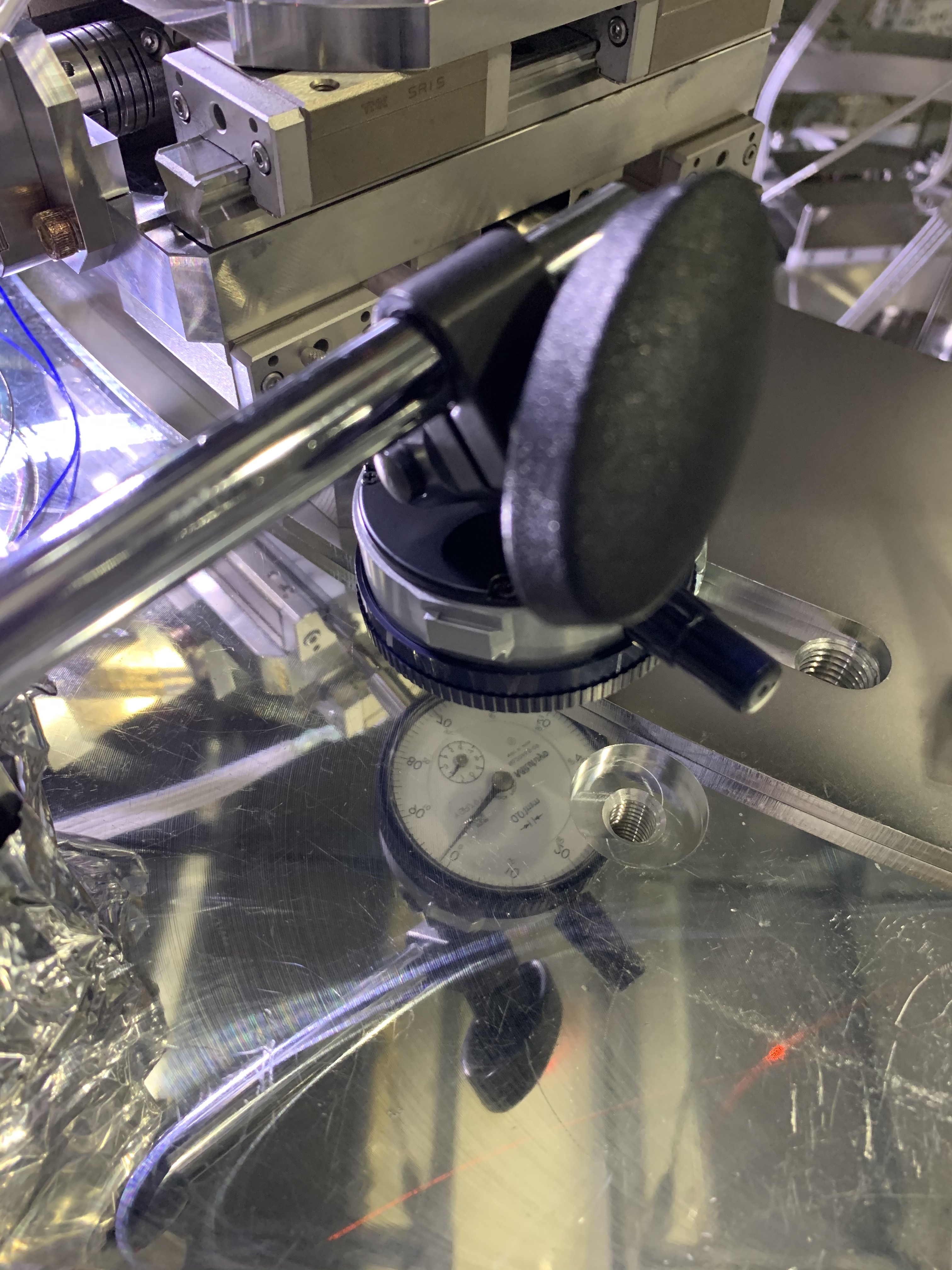
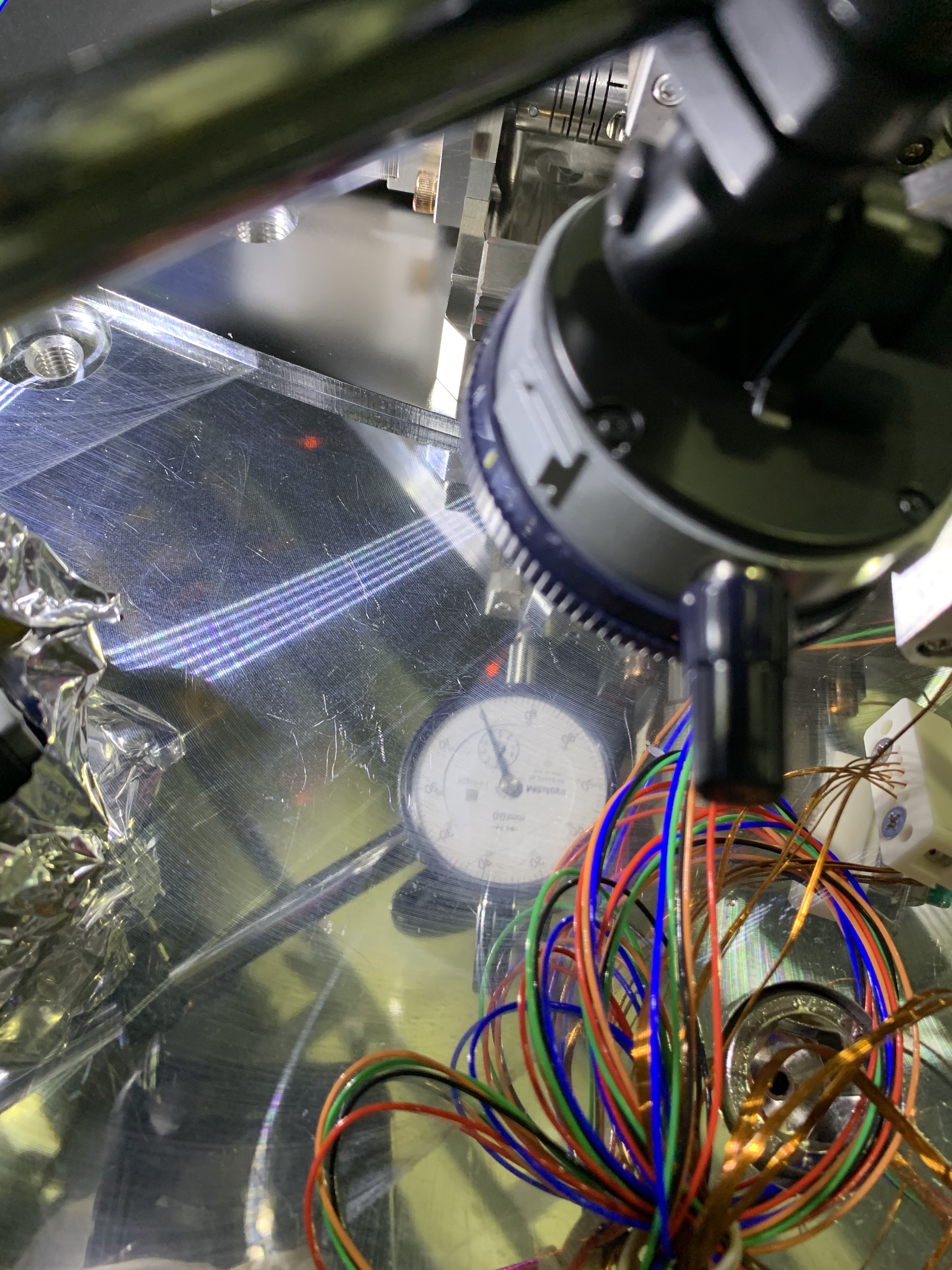
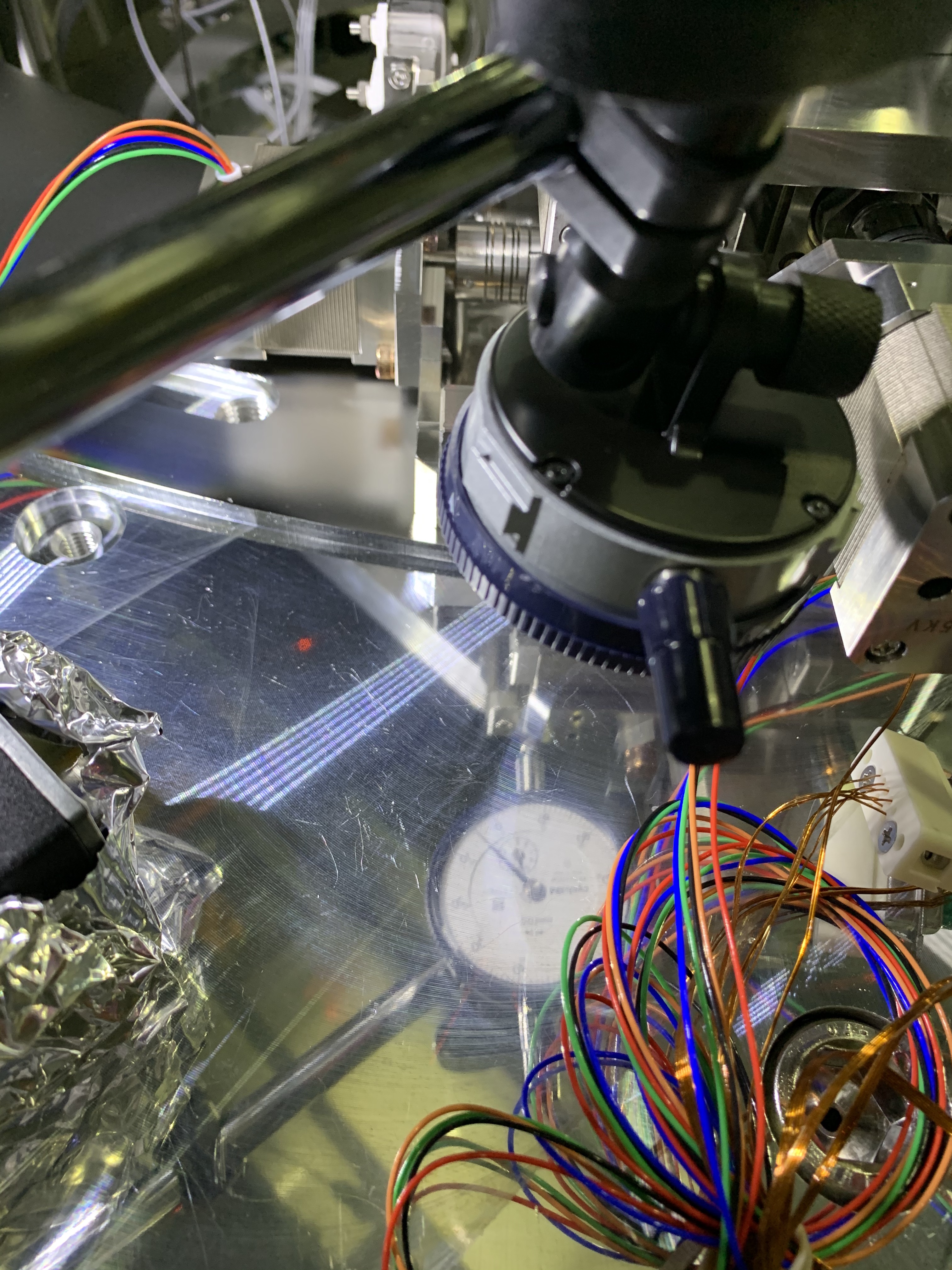
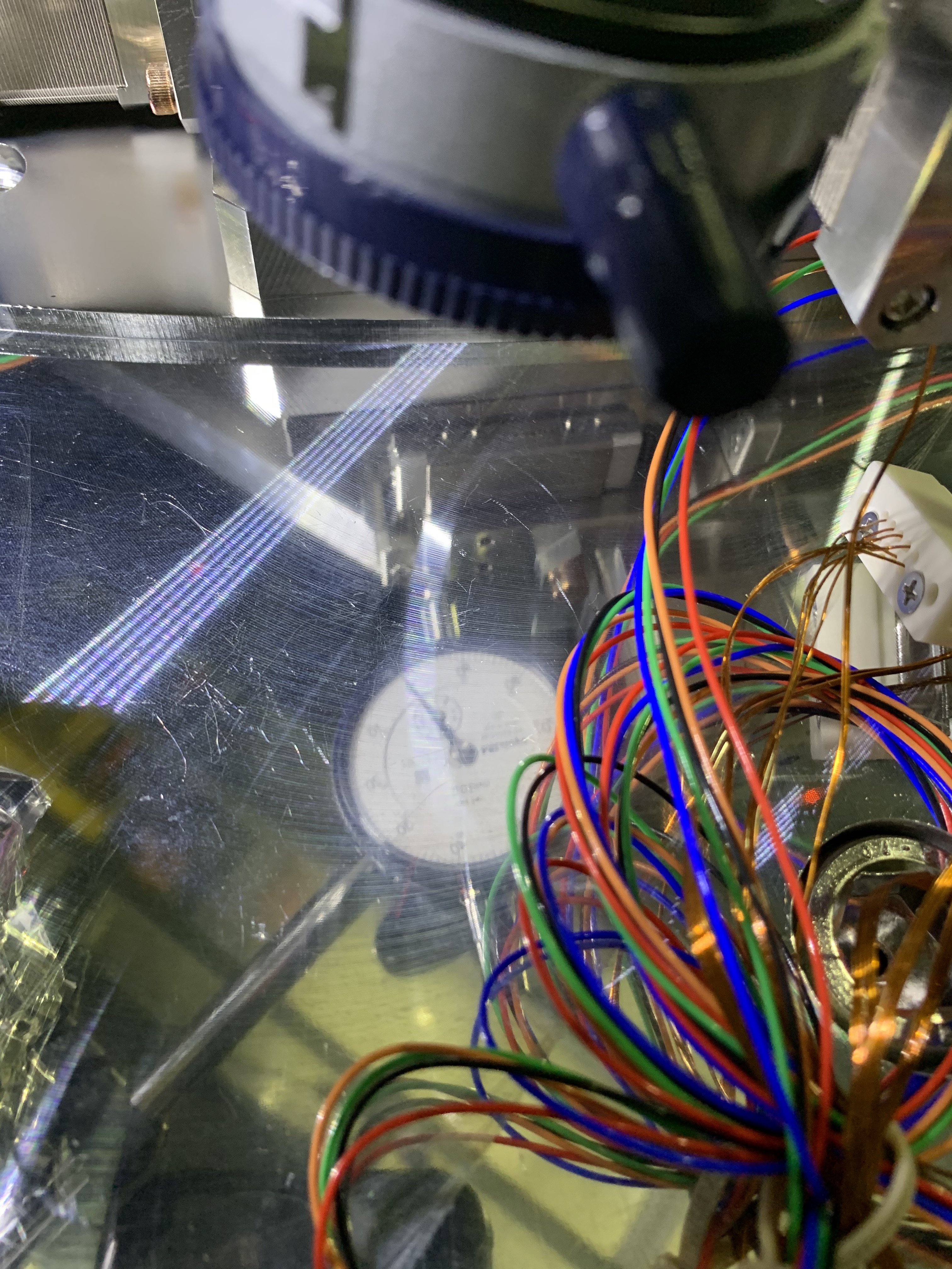
  • We wanted to check the motion of the motors themselves, so we set dial gauges directly onto the moving stages.
  • Due to the height of the stages we had to set the dial gauge downwards and use an inspection mirror to read it. See this picture and others in the album. Likely, there's some paralax error in this configuration.
  • We had to fix the dial gauge base with C-clamps because its is magnetic and the supposting surface is aluminium.

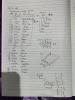
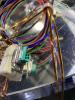
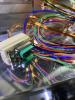
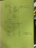
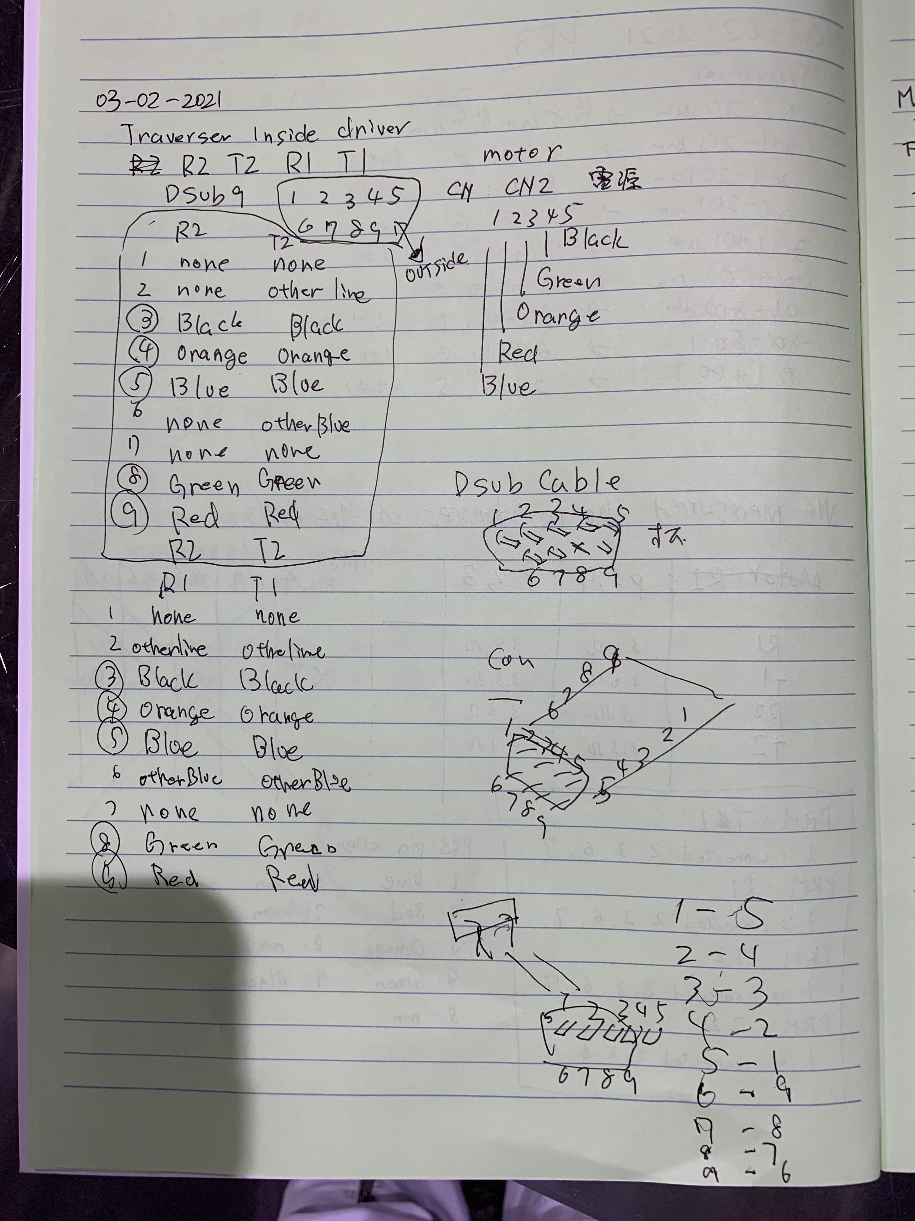
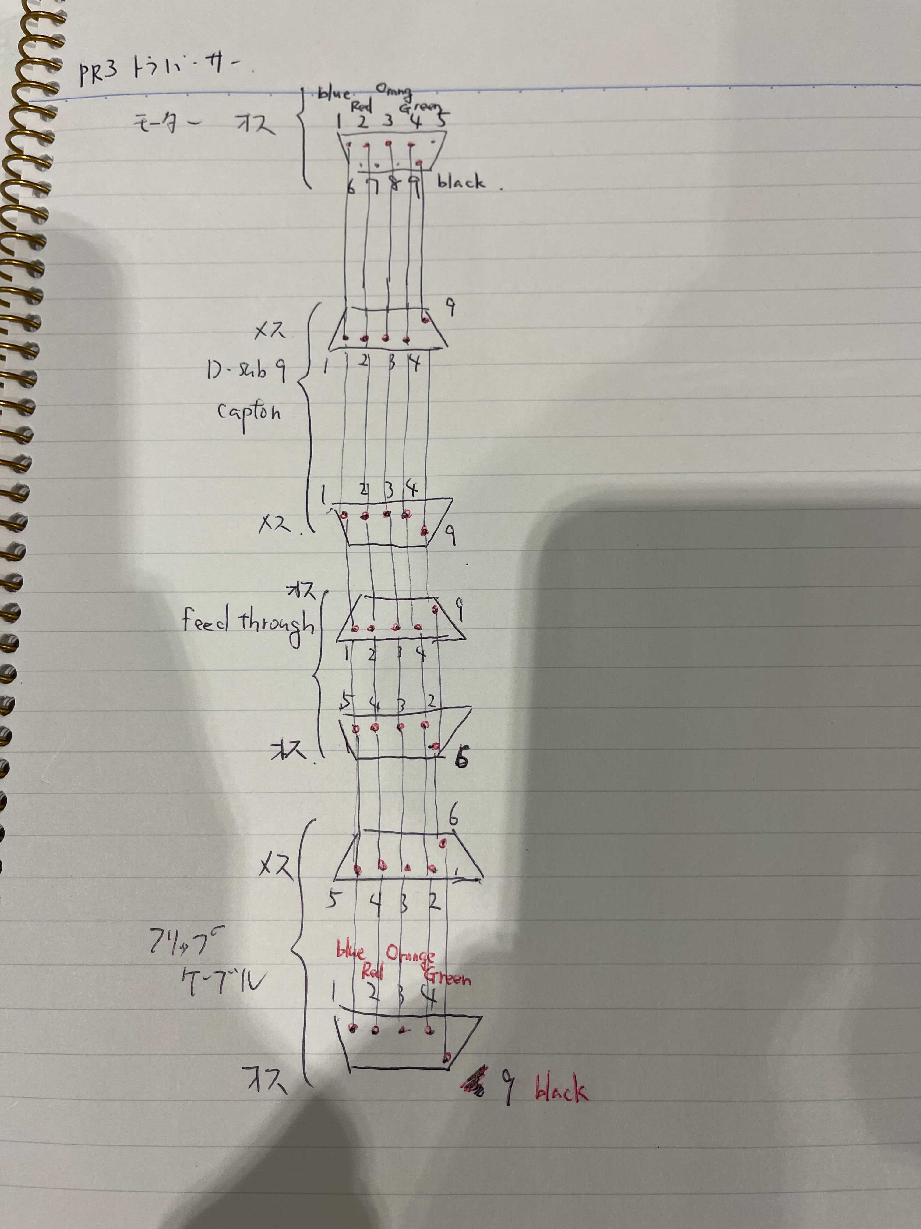
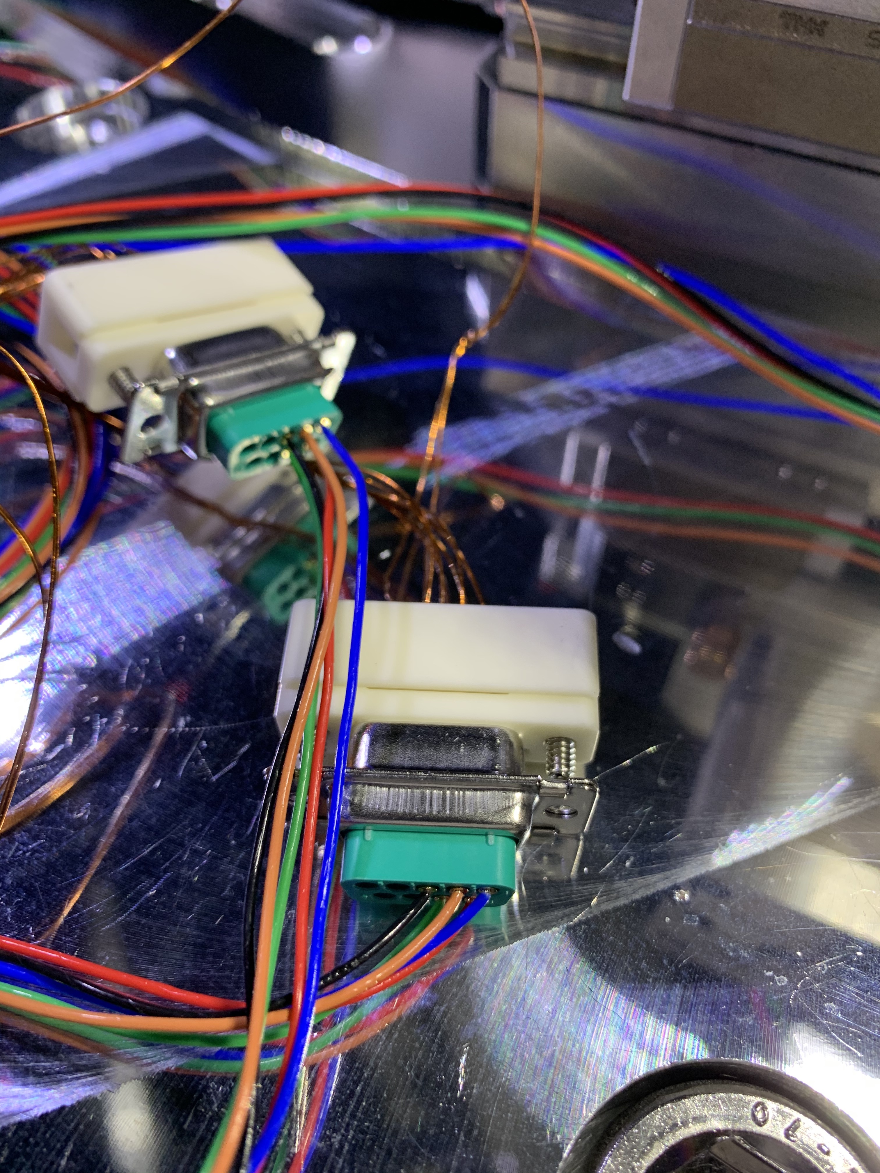
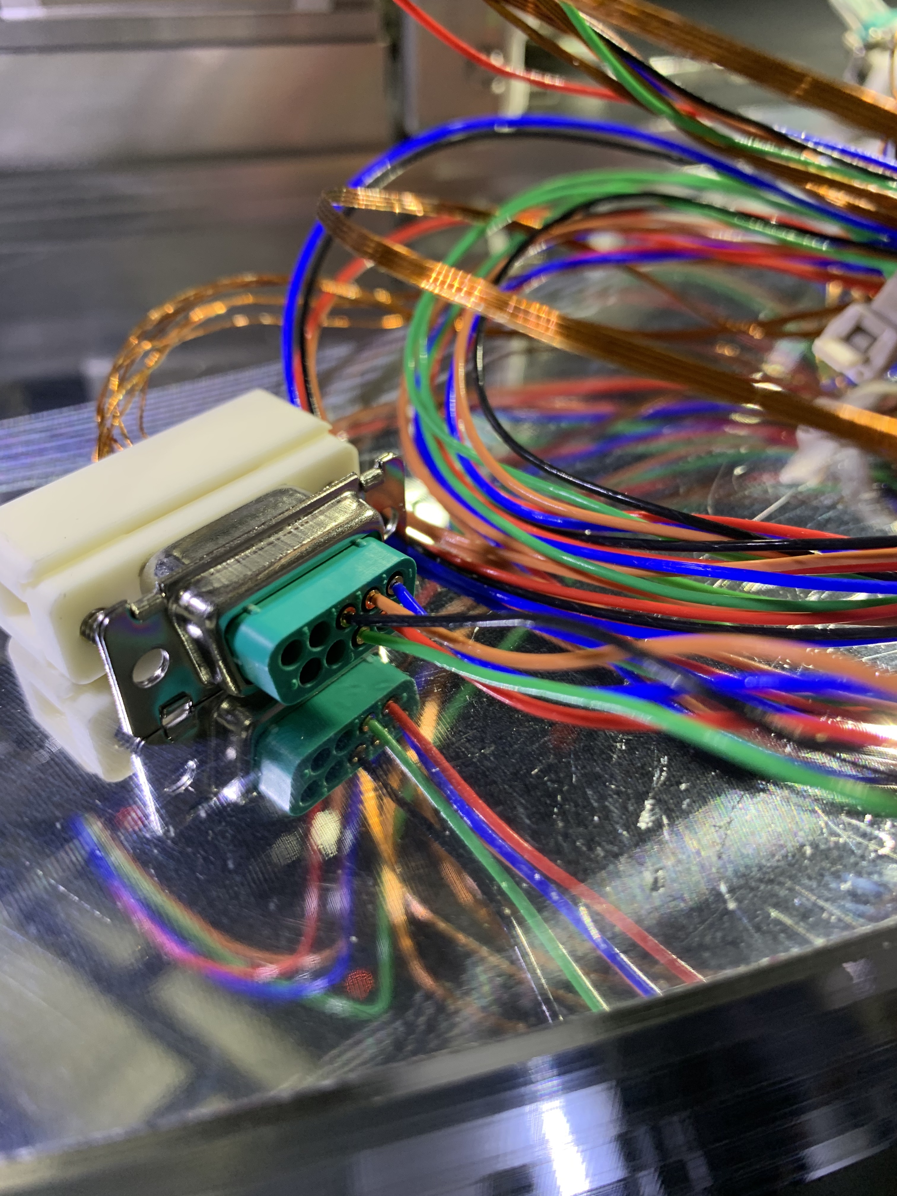
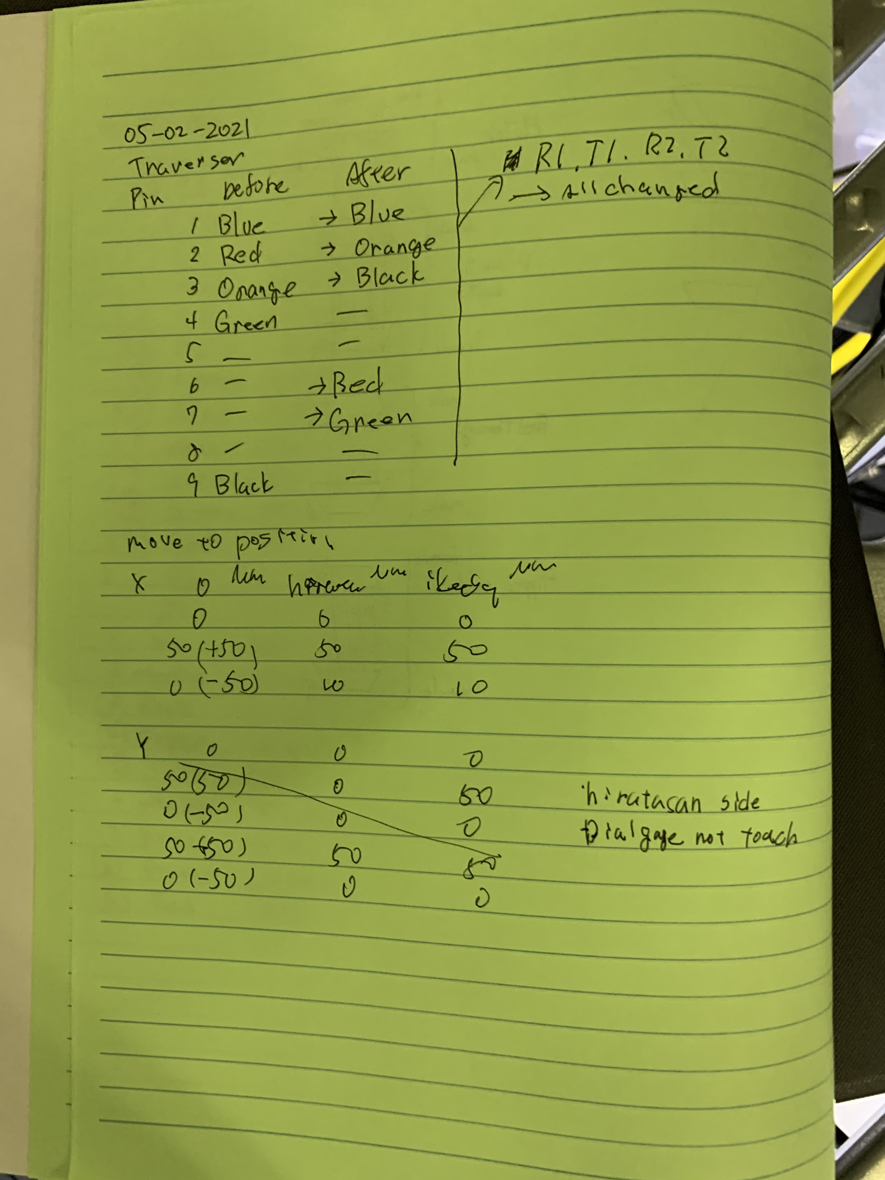
However, the traverser didn't move as expected. It barely moved and when it did, it moved in an irregular way. We measured the resistances between pins at the adapter ouitside of the chamber for the four motors. Between pins 1 and 9 and between pins 2 and 3 there were resistance values of around 3.4 Ohm.  See a table in this notebook page

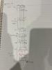
We were wondering what's wrong so de decided to check the connections in PRM and PR2. In those suspensions pins 1,2,3,6 and 7 are connected together. Pins 4,5,8 and 9 are not connected to any other pin. Likely the traverser driver only works for PR2 and PRM. We will check tomorrow.    

Comments to this report:
satoru.ikeda - 21:30 Tuesday 02 February 2021 (15890) Print this report

I ran a Python script against the PR3 Traverser.

The script is documented in the KAGRA Wiki.

It did not work as expected as reported by Fabian-san.

Therefore, I investigated the configuration of the motor driver.
It seems that the contents of the Traverser motor driver consists of an FP0R-C16CT and four CVD507-Ks.

JGW-T1503899

From the CN2 pin of this CVD507-K, it is connected to each color cable of the motor via a serial connector.
This connection is necessary.
It is not possible to change this pinout in the script.

Do it next time.
Check the pin layout on the motor controller side and the pin layout of the serial connector.
Check which of the serial connector and the color cable of the motor are connected.
 

Non-image files attached to this comment
satoru.ikeda - 18:07 Wednesday 03 February 2021 (15911) Print this report

[Ikeda, Fabian-san, Hirata-san]

I have checked the wiring of the Traver motor driver.

The wiring inside the motor driver is summarized below.
JGW-E2112507

After some research, I found that the PR3 is wired exactly as Fabian describes, K-Log #15889.
This is not connected to the terminals required by the motor driver side.

It is also written in K-Log#581.
> The 5 pin is moved to 9 pin, then we can actuate all the motors.
This means that the Black cable is moved.

The 5 pin is moved to 9 pin, then we can actuate all the motors.

I'll check the wiring in the PR2 chamber tomorrow, but I'm assuming it's normal.
K-Log#9262 shows the pin assignments for PR2.
If this is the outer pin assignment of the Feed through, then the FlipCable will connect to the motor driver correctly.
This will be confirmed next time.
 

Images attached to this comment
Non-image files attached to this comment
satoru.ikeda - 21:10 Wednesday 03 February 2021 (15920) Print this report

Supplemental Information on Pin Assignment in PR3

JGW-D1604795

Checking this document, the Pin 1, 2, 3, 4, and 9 used in PR3 were the same wiring used in iKAGRA.
Also, the motor driver side was also wired this way.

It seems correct to assume that the PR3 is still wired the same as the iKAGRA.

Perhaps the motor driver used in the PR3 exists separately from the PRM/PR2.

Non-image files attached to this comment
satoru.ikeda - 13:22 Friday 05 February 2021 (15944) Print this report

[Ikeda, Hirata-san]

We have changed the pinout from the motor to the D-Sub9pin connector on the PR3 traverser.
We modified it to match the pinout of the PR2 and motor driver.

PR3 Traverser Pin Assign
Pin Before After
1 Blue Blue
2 Red Orange
3 Orange Black
4 Green -
5 - -
6 - Red
7 - Green
8 - -
9 Black -

JGW-E2112507-v3


After the modification, the dial gauge was installed and the motor was driven.
We drove the motor from 0 to 50[um] and 0[um] for X(T) and Y(R), respectively, and read the scale of the dial gauge.
It was confirmed that the dials were driven to the specified positions.
X did not return by about 10[um] in the reading of the dial gauge when it was returned to the 0 position, but we judged that it returned to the original position because of the hysteresis and reading error.

From then on, the PR2 and PR3 traversers work directly on the cable with the motor driver () without having to connect a special transducer.

Images attached to this comment
Non-image files attached to this comment
satoru.ikeda - 20:32 Friday 12 February 2021 (16001) Print this report

Comments related to K-Log #15930, #15944, #15911, #15920.

I found two Traverser motor drivers and a conversion cable for Pin placement at the Hokubu-Kaikan.
Together with the one currently in the PR3 mini-rack, I now have three units.
I changed the Pin placement in K-Log #15944, so the conversion cable is no longer needed.

Images attached to this comment
Non-image files attached to this comment
satoru.ikeda - 8:46 Tuesday 16 February 2021 (16027) Print this report
Non-image files attached to this comment
Search Help
×

Warning

×