Yesterday, I took advantage of the suspended mode of KAGRA to investigate the strange response of the geophones installed on the Type A suspensions.
As reported in the klog 10334 the geophone shows strange phase response and this make hard to implement a suitable Inertial damping with blending frequency below 0.2 Hz.
After many discussions with Shoda-san and Aso-san, we figured out that this strange behavior could be associated with the calibration filter of the geophone used to change the signal into speed.
The geophone has an other big problem: It shows an huge DC noise. To reduce it, in the standard setting, the calibration filter with a 10 mHz cutoff has been implemented (4 poles at 0.01 Hz). As results of this implementation the DC noise is suppressed, but a phase shift of several degree is induced and It is well visible if we measure the TF= GEO/(LVDT*w).
To see if the phase could be fixed in digital way, we decided to make some trial by moving back the cutoff (3 mHz).
Below some details of the Yesterday's works.
%%%%%%%%
I measured:
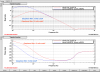
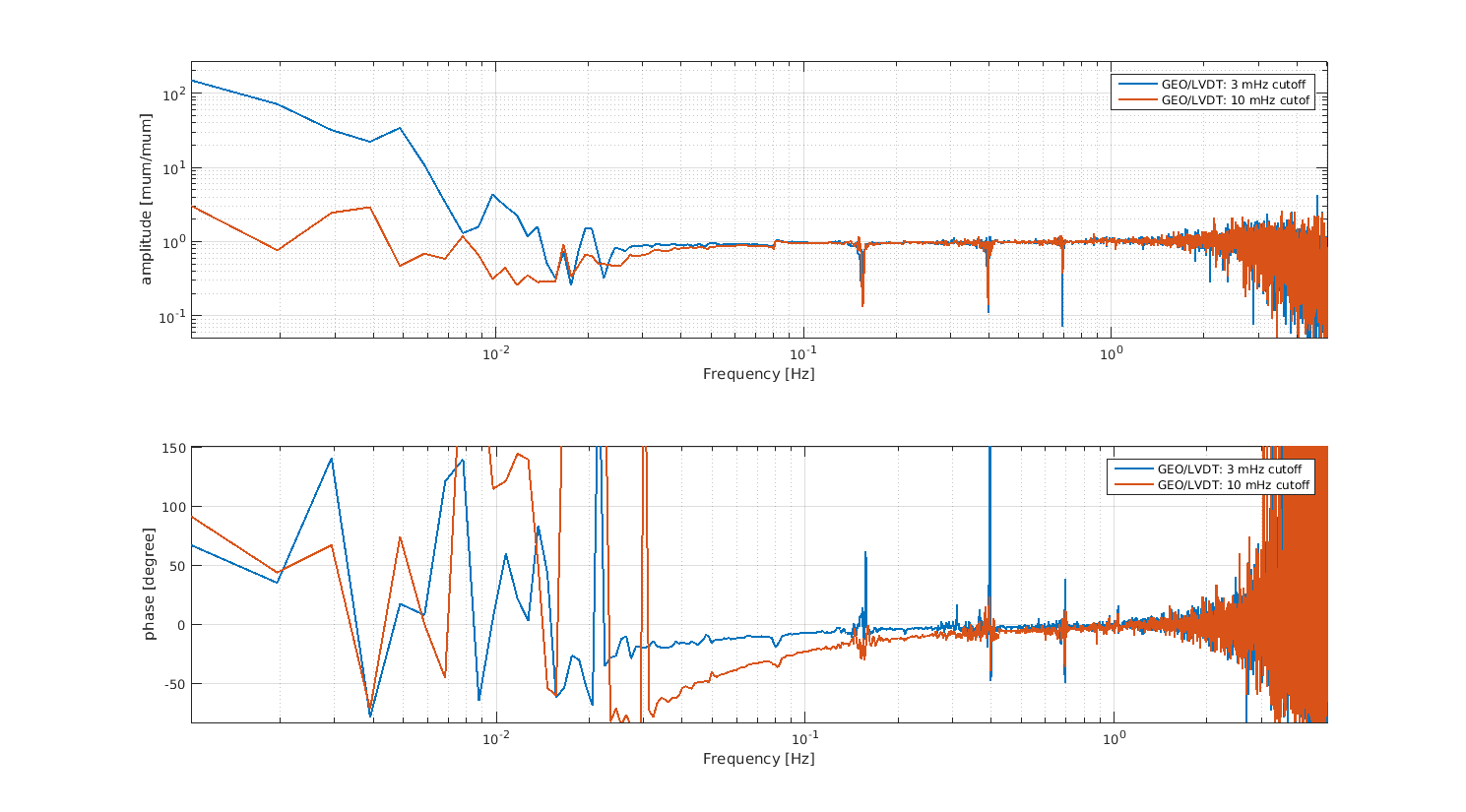
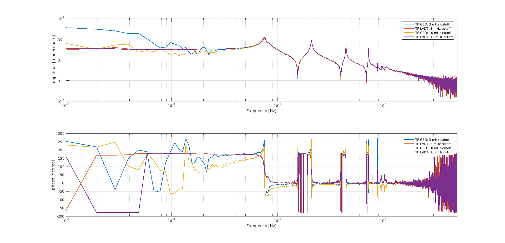
- TF= GEO/(LVDT*w) as well as the mechanical TFs when calibration filters with 10 mHz and 3 mHz cutoff have been measured (see Pic1, Pic2, Pic3 respectively).
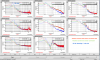
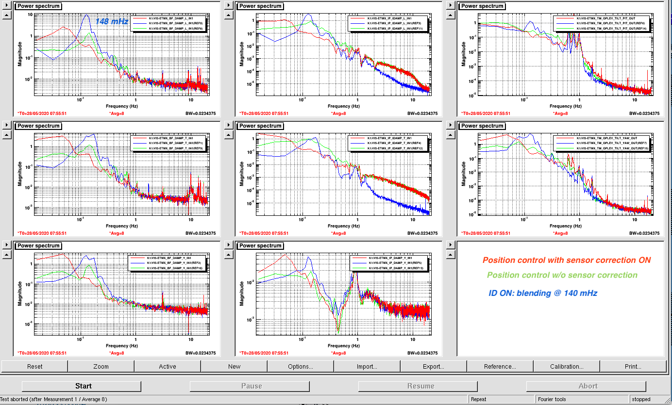
- I turned on the ID with blending frequency @ 140 mHz (Pic4 show the results).
- I measure the spectra of LVDT and geophone when the only the position control is turned on (Pic 5 and Pic6).
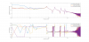
-In Pic2 we can see that by moving back to 3 mHz the DC cutoff the phase shift is reduced a lot, but the DC noise is growing up (see also Pic3).
- The intercalibration geophone/LVDT (done by using the procedure reported in this klog 7341) looks fine (magnitude of GEO/(LVDT*w)=1)
- TF_LVDT = TF_GEO/w and the phase lag between geophones and LVDTs is pi/2 as expected (Pic3)
- Pic 4 shows the spectra when ID, position control and sensor correction (without ID) are turned on.
By looking at this spectra we can see the @ 148 mHz peack got excited when the ID is on: maybe some excess of the geophone noise is exciting this peack?
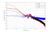
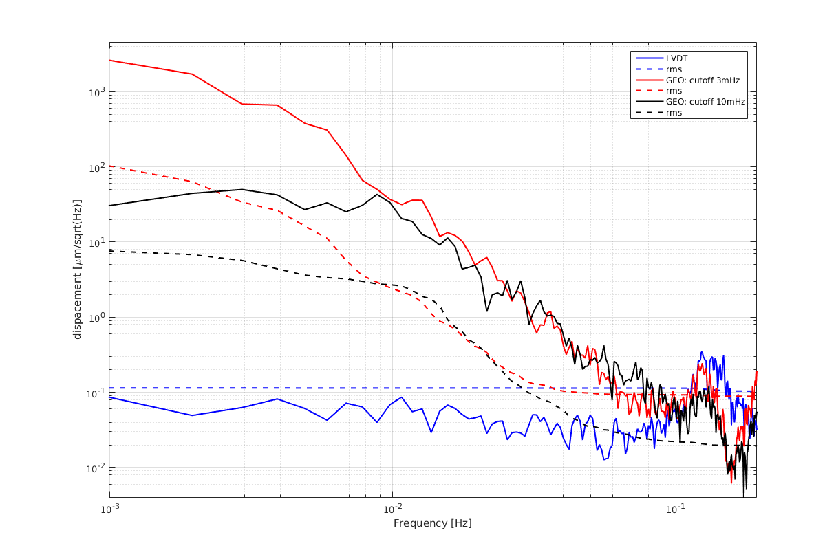
-Pic 5 and Pic 6 show the comparison between the LVDT and geophone spectra when the 10 mHz and 3 mHz cutoff are implemented on the geophone and when the IP LVDT control is on (without sensor correction).
We can see that:
- LVDT and GEO spectra are the same in the microseimic region (0.1, 0.6 Hz): the sensors are measuring the same amount of IP's displacement.
- below 0.1 Hz the LVDT (sensor in loop) is measuring the IP residual motion: 0.1 micron in DC
- below 0.1 Hz the geophone signal is too large compared with LVDT one and It is getting worse we change the cutoff from 10 mHz to 3 mHz:
GEO: 10 micron in DC (10 mHz cutoff ) to 100 micron in DC (3 mHz cutoff).
Since below 0.1 Hz not strange behaviors of the IP (like cradle effect see klog 10334 ) have been manifested so far, the large mismatch between LVDT and GEO signal can be explained just by an excess of DC noise.
Conclusions:
It is true that It is possible to reduce the phase shift of the geophone by moving back the cutoff frequency, but the effect is to increase of a factor 10 the DC noise of the geophones (among other things already huge) and to excite the 148 mHz peack when the geophone is used in the blending technique.
More investigation to understand where the geophone noise is coming from should be performed.

