[Lucia, Y. Fujii, Eleonora]
= Geophones calibration=
Assuming that the IP LVDT driving and sensing calibration is correct we used it to intercalibrate the IP geophones.
We follow the same procedure used for the accelerometers on ITMX IP ( see entry #7134).
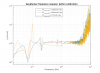
We injected noise in Yaw and measured the ratio between LVDT yaw and each geophone response (converted in diplacement): (Yaw_LVDT*r)/(GEO)/(w)
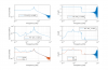
Such function (shown on pic1) should be flat in the region from 100 mHz to ~2 Hz. We remarked that there are some structures at 200 mHz and GEO3 has a strange, not flat behaviour.
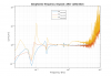
The extrapolated calibration factors are:
| cal G1 at 0.5 Hz | 1.250 |
| cal G2 at 0.5 Hz | 1.045 |
| cal G3 at 0.5 Hz | 0.77 |
As expected, after implementing the calibration the fuction is one in the flat region (pic 2), but GEO3 is higher above 1 Hz.
=Geophones sensing matrix=
Then we have computed the diagoanlized sensing matrix by injecting a line at 2 Hz for each d.o.f and measuring the amplitude and phase of the TF between each GEO (converted in displacement) and the diagonalized LVDT sensor.
TF_ji = (GEO_j/(2pi*f0))/LVDT_i j = 1, 2, 3 i = L, T, Y f0 = 2 Hz.
This values are reported in a matrix where the columns correspond to L, T and Y and the lines to the three geophones.
The sensing matrix, is computed as the inverse of such matrix, and it is reported below:
| H1 | H2 | H3 | |
| -0.6021 | 0.1258 | 0.409 | GEO_L |
| -0.0088 | 0.59510 | -0.9051 | GEO_T |
| -0.5128 | -0.7096 | -1.0556 |
GEO_Y |
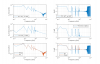
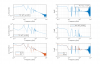
As a final check for this procedure we compared the TF measured injeecting noise from the diagonalized virtual acutators and looking at the diagonalized LVDT and geophones.
We verified that TF_LVDT = TF_GEO/w (See Pic 3, 4, 5). The phase lag between geophones and LVDTs is pi/2 as expected.