With the kind help of Paolo Ruggi (Virgo collaborations)
One possible reason of the blending failure below 100 mHz could be the “cradle effect”.
It is a mechanical coupling between longitudinal translation of the base ring and angular tilt of the top table and It can be due to a non perfect parallelism of the IP legs.
A way to detect this effect is to measure the TF between LVDT and Inertial sensor.
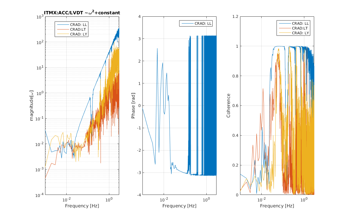
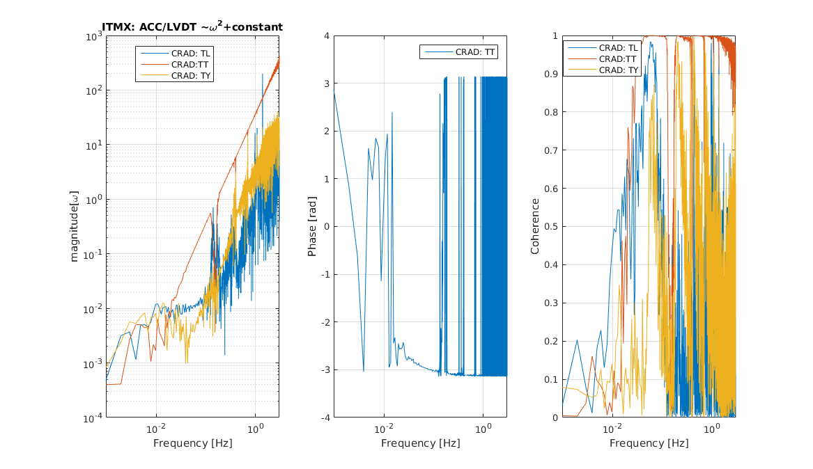
In the Ideal case (when the IPs legs are parallel) and if use the accelerometer we expect the ACC/LVDT~ (w)^2, while if the cradle is present the TF is ~a+w^2 with a~theta/x~b/(L*R).
where b is the parallelism error, L is length of legs and R is half distance between the legs.
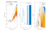
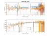
Pic1 and Pic2 show the Cradle estimation in ITMX along L and T direction respectively:
-along L: a~0.01
-along T is negligible
It seems that that this effect for KAGRA IPs is very low.
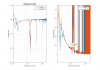
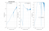
Pic3 show the TF= ACC/(LVDT*(w)^2).
We can see:
-the magnitude is about 1
-the phase difference ranges from 7 degree at 0.1 Hz to 1 at 0.2.
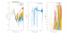
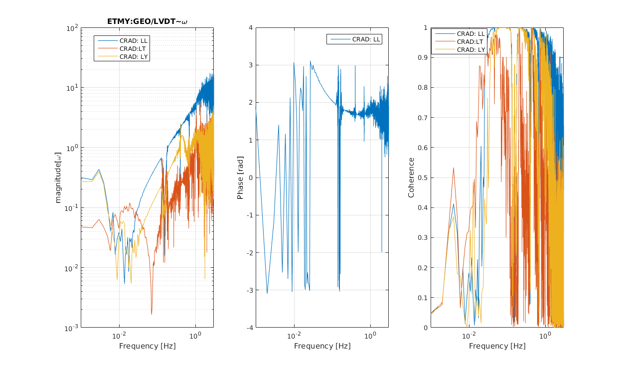
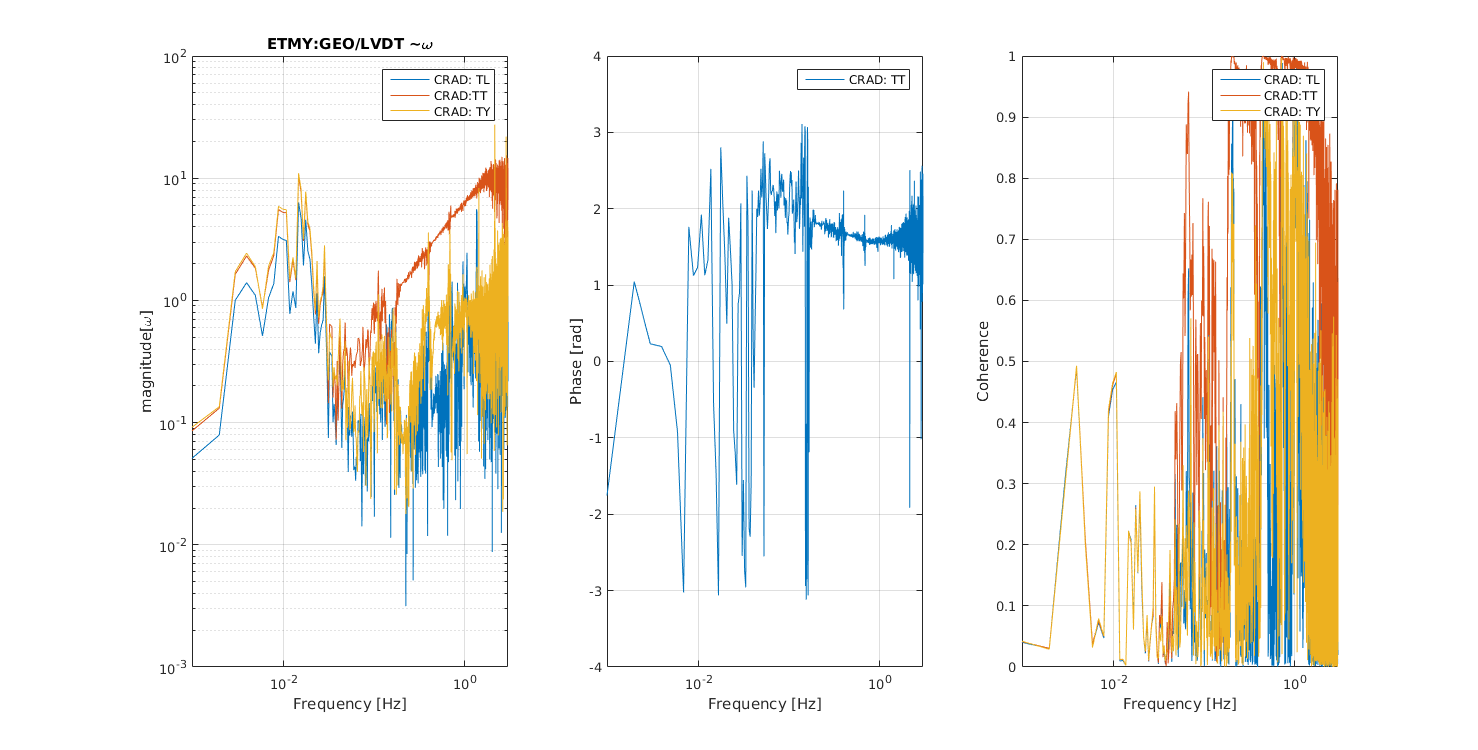
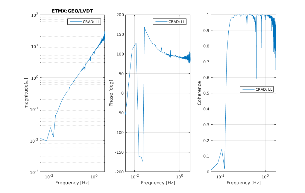
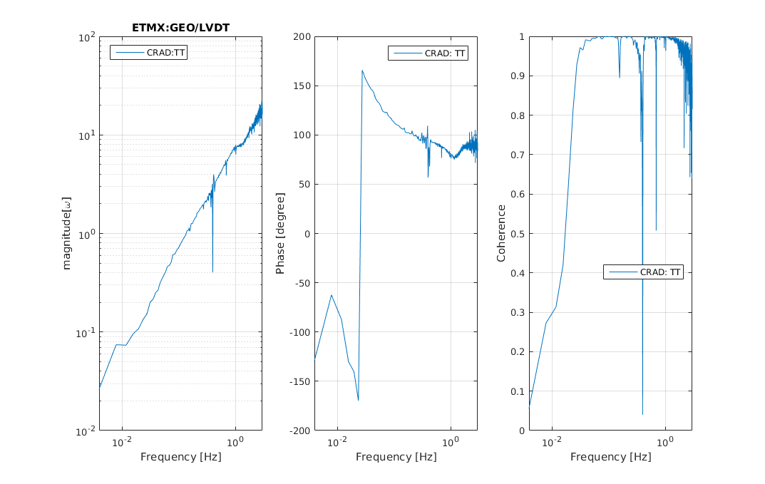
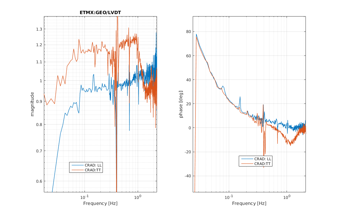
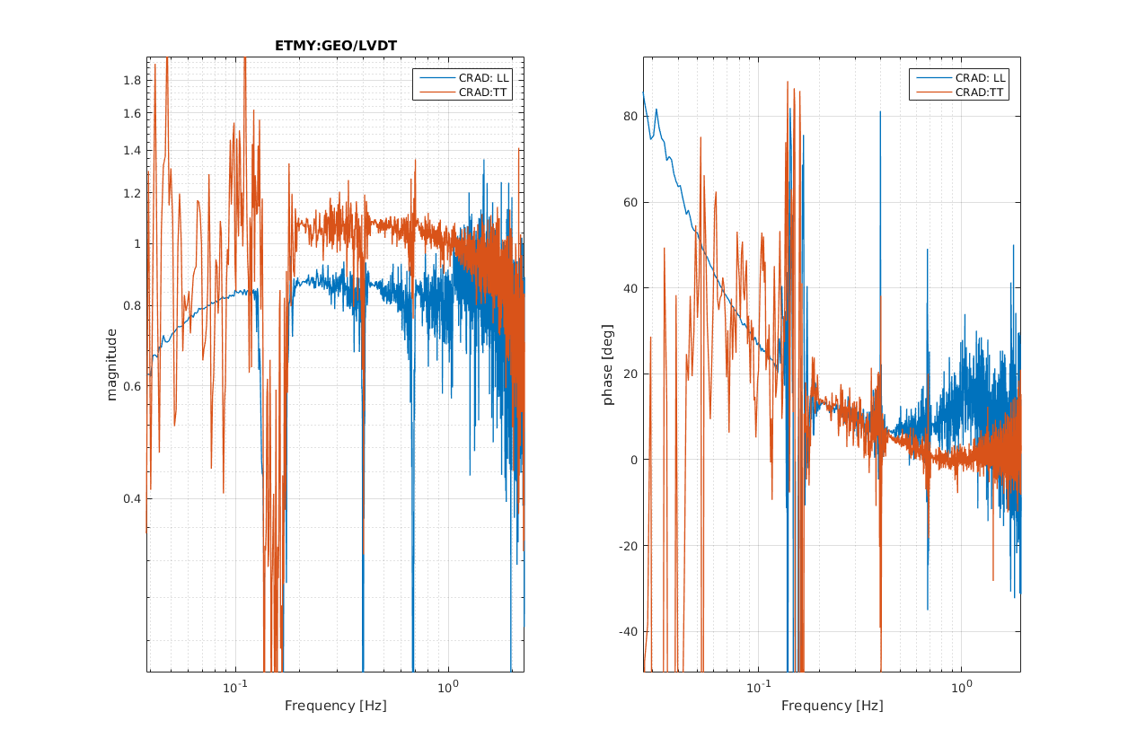
I measured the same TFs by using the geophones at EY and EX; in this case I expected to see a+w in the magnitude and 90 degree in the phase.
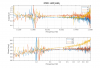
Pic4, Pic5, Pic6, Pic7 show the Cradle estimation for the End IPs along L and T direction respectively: In these cases because of the strange phase behavior I cannot estimate the cradle contributions.
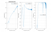
Pic8 and Pic9 show the TF= GEO(LVDT*w).
-the magnitude ranges from 0.8 to 1.1
-the phase difference ranges from 30 degrees at 0.1 Hz to 1degree at 0.7 Hz.
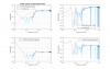
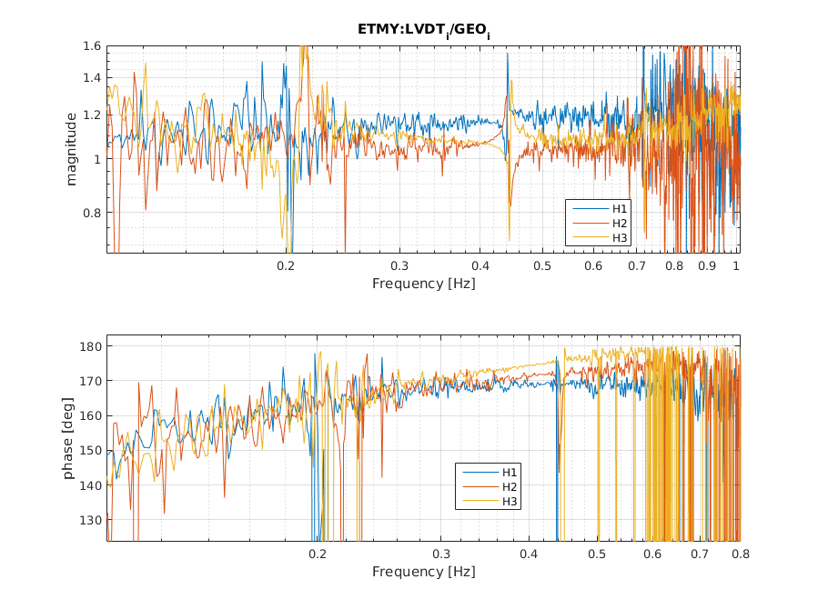
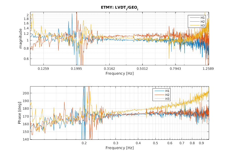
To undestand if this is an artfact or if It is the real behaviors of the geophones, I measured the TFs: LVDT_Hi/GEO_Hi (see Pic10 and Pic11):
-the phase difference ranges from 30 degrees at 0.1 Hz to 1degree at 0.7 Hz.
This phase shift in the geophone and in the accelerometer could explain why all blending below 0.3Hz (for geophones) and 0.1 Hz (for acc) induce large oscillations at BF stage.
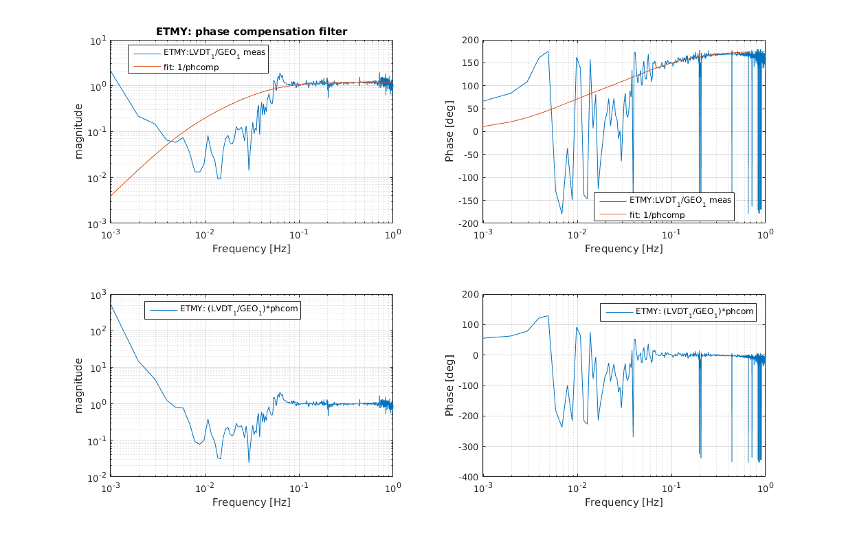
I tried to fit these TFs in order to equalize the phase response of the geophones (Pic12), but in the model I need to use one pole with negative frequency.
By using a phase compansation filter in principle is possible to equalize the geophone sensors to the LVDTs, but these compensations would bring up the low frequency noise of the geophones.
If in the future, we want to use the geophones we need to think how to shape a good phase compansation filter for the geophones.


