K. Miyo, Y. Fujii,
Brief update:
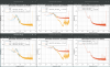
- Concerning the plot in klog#10179, it was found that the sign of the initial value was opposite from the optimal one. Figure 1 is the revised one; gain optimization did not change the situation. Basicaly the gain was aready aligned.
-
Except for this, for further tuning, we tried to modify the sensor correction filter for IP-L, so that the phase shift at around 0.1 Hz is 0 deg.
-
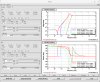
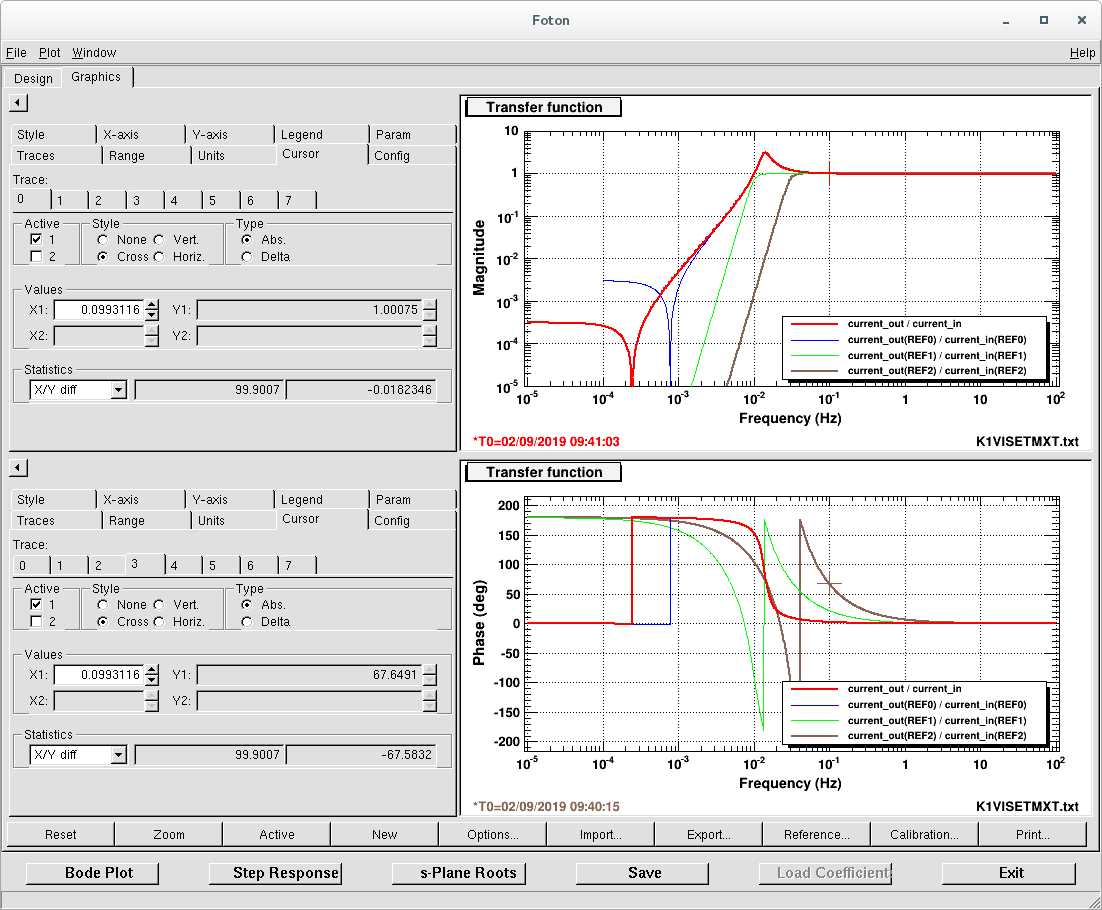
Figure 2 shows the tested filters:
- brown: the currently implemented one, 6th-Butter w/ 30mHz cut-off (1)
- green: 6th-Butter w/ 10mHz cut-off (2)
- red: 2nd-order, 80dB-attenuation, 10dB-passband, 0.01Hz cut-off (3)
-
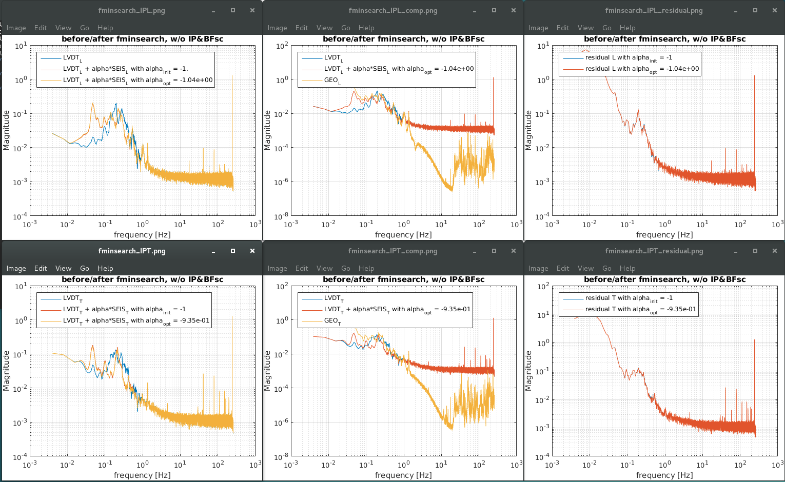
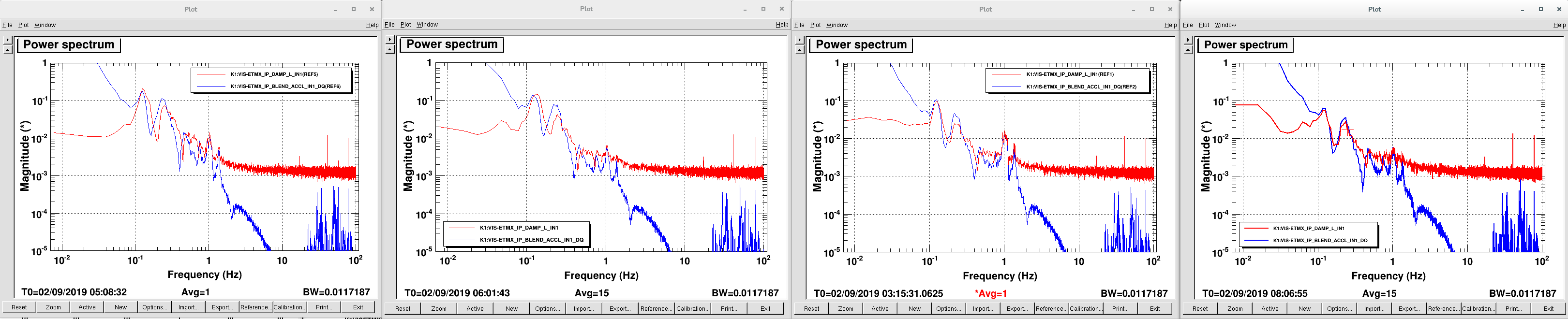
Figure 3 shows the comparison between the corrected-VDT and the geophones:
- w/o sensor-correction(sc) | (1) | (2) | (3)
- It seemed that the TML oplev signal just showed the ground motion or noise level, and no obvious improvement was observed. To be checked (with simuation as well).
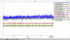
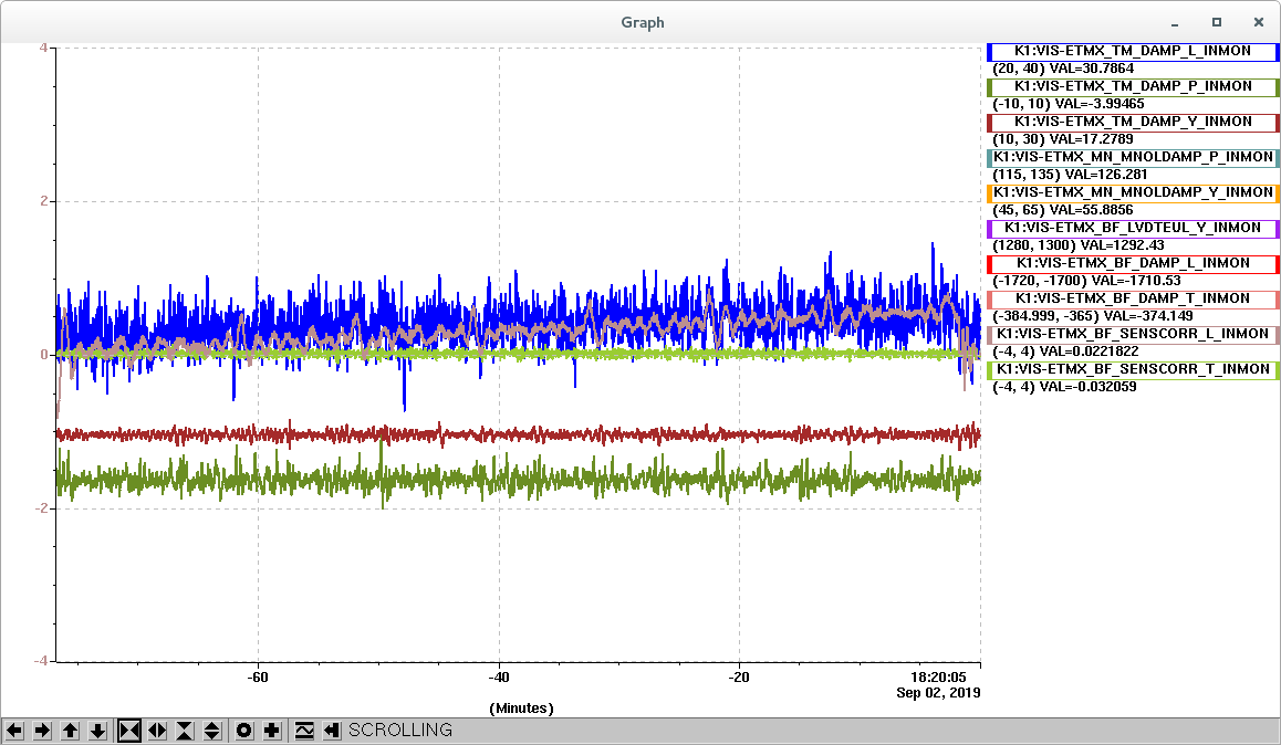
- It was found that the (3) fiter made a long-term drift as shown in figure 4, the low frequency shape of thte filter would be modified. The brown is thte output of the correction filter, and the blue one is the TML oplev signal.
-
Figure 2 shows the tested filters:
- Now the configuration is back to the this morning's.
-
For next:
- modify the sc-filter in lower frequemcy region.
- check the performance with the silumation.
- modify the IP loop hsape/gain.
