The network cable connector claw seems not to be properly fixed in the GigE cam even if I tried to push the connector to the GigE cam. So I attached an additional short network cable with the extension connector as the attached photo. In this case, the connector claw could be fixed properly. After that, I confirmed the PMC trans image could be displayed.

The water for the chiller was replaced from distilled water to tap water.
The image of PMC trans was lost maybe because of the disconnection of the network cable that had no claw in the Gige cam. I will check in this afternoon.
[Tanaka, Miyoki, Takase]
Summary
We recovered the BD chiller water circulation. So the FB output was set at the default current of 27.8A(~18W).
What we did
Firstly, we tried the water flow check of the Adjuster BD solely. We confirmed that the water flow is enough.
Secondly, we attached the the yellow tube to the chiller return and the transparent tubes from the PMC BD on the Adjuster BD in the space above the edge of the optical table after turn off the FB amp part (So the IR power was tiny round PMC). Then we put the Adjuster BD in the water basket and checked the water flow by operating the chiller. We confirmed the water flow in the all water paths and BDs. Actually, we sensed the BD temperature was cool by fingers.
The chiller was stopped again.
Thirdly, we replaced the 30W detectable power meter head with the recovered Adjuster BD. In this process, we found that the water tubes interfered with the PEM mike that was suspended from the metal mesh. So we pulled up the mike about 30cm to avoid interference. After that we also replaced the 50W detectable power meter with the original PMC BD at the rough position. Then we turned on the FB and got ~ 1W laser power. We realocated the PMC BD to have the beam be at the center. After that, PMC was locked, and we djusted the Adjuster BD height to introduce it at the center of the Adjuster BD. We also confirmed that the temperature of the PMC/Adjuster BD around was 20C by using the non-contacting type thermometer.
We restarted the chiller.
Fourthly, we increased the current of the FB upto 27.8A (~ 18W). If there was no water circulation, the temperature of the Adjuster BD became ~40C degrees when the FB output was 10W with in 30 minutes or so. After the recovery the chiller path for BDs, the temps of the Adjuster/PMC BDs were 21C just after the FB laser operation. After ~40minutes later, we checked the temps again, and got ~22C. So we recognized that the water chiller system was working well.
Tanaka, Miyoki, Uchiyama, Yuzu, Takase,
[Summary]
The stuck existed in the Adjuster BD.
[What we did]
After the STM2 cable cut and the STM1 cable fixing, we restarted the search for the stuck position in the water path in the BDs chiller path in the PSL room.
We replaced the Adjuster BD with 30W detectable power detector. Because the water tubes that are attached to the Adjuster BD were fixed on the ceiling metal mesh above around the center of the optical table, we scarcely could move the Adjuster BD just above the edge of the optical table.
At this position, we removed the yellow tube that directly went to the chiller return side above a water basket. We found there was almost no water in the yellow tube. When we injected air by using air duster can into this yellow tube, the return side had also slight water and air. In this sense, this yellow tube had no stuck.
After that, we checked the Adjuste BD itself. We injected air by using the air duster can to the water input where the transparent tube was connected (this tube came from the PMC BD), and checked whether the air could come out from the other side water input where the yellow tube was connected or not. Consequently, there was no airflow could path through the Adjuster BD even though I tried 3 times. After that, I retried the same air injection from the other side. The first trial failed to the air pass through. However, the second trial succeeded in letting the air pass through the BD with some dirty pieces as shown in the photo. After this first air conduction, all air injection trials have succeeded in passing through the BD. So we concluded that, at least this Adjuster BD had stuck.
After that, we injected air to the transparent tube that was connected to the PMC BD to check the airflow to the output side of the chiller through the shutter BD and several tubes. Then we obtained the expected airflow! So we concluded that there was no stuck in PMC BD and Shutter BD and their tubes.

From around 14:00, Ushiba-kun tried to LSC lock of IMC and it suceeded. However, ASC did not work even though it seemed to work in the morning time. After several checks of IMMT1 trans and so on, he suspected the laser beam was hidden by something at somewhere. Finally, we found the aluminum foil between IFI and IMMT was shading the beam! The aluminum foils inside seemed to roll inside because of no fixing and its rolling seemed to shade the beam.
Ushiba-kun, Hitrata-san and I fixed this nasty aluminum foil coveres. After that the IMC lock with LSC and ASC was successfully done.
> At the same time, the cleaning in the water vessel of the original chiller was done.
I attached the photos for the record. [before the cleaning] [after the cleaning]


[miyoki, tanaka, yuzu, takase]
We replaced the PMC REFL BD with the 50W detectable power meter. the PMC REFL BD was just reset at other place near the original position on the same optical table in the PSL room.
Adter that, Tanaka-kun set the FB laser power at 10W to investigated the lock of PMC and IMC. PMC and IMC was successfully locked, and ASC seemed to work because the IMC output increased after angaging.
At the same time, the cleaning in the water vessel of the original chiller was done.
> At the same time, the cleaning in the water vessel of the original chiller was done.
I attached the photos for the record. [before the cleaning] [after the cleaning]
From around 14:00, Ushiba-kun tried to LSC lock of IMC and it suceeded. However, ASC did not work even though it seemed to work in the morning time. After several checks of IMMT1 trans and so on, he suspected the laser beam was hidden by something at somewhere. Finally, we found the aluminum foil between IFI and IMMT was shading the beam! The aluminum foils inside seemed to roll inside because of no fixing and its rolling seemed to shade the beam.
Ushiba-kun, Hitrata-san and I fixed this nasty aluminum foil coveres. After that the IMC lock with LSC and ASC was successfully done.
Tanaka, Miyoki, Uchiyama, Yuzu, Takase,
[Summary]
The stuck existed in the Adjuster BD.
[What we did]
After the STM2 cable cut and the STM1 cable fixing, we restarted the search for the stuck position in the water path in the BDs chiller path in the PSL room.
We replaced the Adjuster BD with 30W detectable power detector. Because the water tubes that are attached to the Adjuster BD were fixed on the ceiling metal mesh above around the center of the optical table, we scarcely could move the Adjuster BD just above the edge of the optical table.
At this position, we removed the yellow tube that directly went to the chiller return side above a water basket. We found there was almost no water in the yellow tube. When we injected air by using air duster can into this yellow tube, the return side had also slight water and air. In this sense, this yellow tube had no stuck.
After that, we checked the Adjuste BD itself. We injected air by using the air duster can to the water input where the transparent tube was connected (this tube came from the PMC BD), and checked whether the air could come out from the other side water input where the yellow tube was connected or not. Consequently, there was no airflow could path through the Adjuster BD even though I tried 3 times. After that, I retried the same air injection from the other side. The first trial failed to the air pass through. However, the second trial succeeded in letting the air pass through the BD with some dirty pieces as shown in the photo. After this first air conduction, all air injection trials have succeeded in passing through the BD. So we concluded that, at least this Adjuster BD had stuck.
After that, we injected air to the transparent tube that was connected to the PMC BD to check the airflow to the output side of the chiller through the shutter BD and several tubes. Then we obtained the expected airflow! So we concluded that there was no stuck in PMC BD and Shutter BD and their tubes.
[Tanaka, Miyoki, Takase]
Summary
We recovered the BD chiller water circulation. So the FB output was set at the default current of 27.8A(~18W).
What we did
Firstly, we tried the water flow check of the Adjuster BD solely. We confirmed that the water flow is enough.
Secondly, we attached the the yellow tube to the chiller return and the transparent tubes from the PMC BD on the Adjuster BD in the space above the edge of the optical table after turn off the FB amp part (So the IR power was tiny round PMC). Then we put the Adjuster BD in the water basket and checked the water flow by operating the chiller. We confirmed the water flow in the all water paths and BDs. Actually, we sensed the BD temperature was cool by fingers.
The chiller was stopped again.
Thirdly, we replaced the 30W detectable power meter head with the recovered Adjuster BD. In this process, we found that the water tubes interfered with the PEM mike that was suspended from the metal mesh. So we pulled up the mike about 30cm to avoid interference. After that we also replaced the 50W detectable power meter with the original PMC BD at the rough position. Then we turned on the FB and got ~ 1W laser power. We realocated the PMC BD to have the beam be at the center. After that, PMC was locked, and we djusted the Adjuster BD height to introduce it at the center of the Adjuster BD. We also confirmed that the temperature of the PMC/Adjuster BD around was 20C by using the non-contacting type thermometer.
We restarted the chiller.
Fourthly, we increased the current of the FB upto 27.8A (~ 18W). If there was no water circulation, the temperature of the Adjuster BD became ~40C degrees when the FB output was 10W with in 30 minutes or so. After the recovery the chiller path for BDs, the temps of the Adjuster/PMC BDs were 21C just after the FB laser operation. After ~40minutes later, we checked the temps again, and got ~22C. So we recognized that the water chiller system was working well.
The image of PMC trans was lost maybe because of the disconnection of the network cable that had no claw in the Gige cam. I will check in this afternoon.
The water for the chiller was replaced from distilled water to tap water.
The network cable connector claw seems not to be properly fixed in the GigE cam even if I tried to push the connector to the GigE cam. So I attached an additional short network cable with the extension connector as the attached photo. In this case, the connector claw could be fixed properly. After that, I confirmed the PMC trans image could be displayed.
It appears that there is some issue with the laser. Trending to the lockloss preceding this failure, it looks like the laser failure caused the lockloss. The lockloss occurred during locking ALS DARM (state 210 of LSC_LOCK). At the time of the lockloss, the laser power drops from about 20W to 1 W.

The water level of the chiller for the fiber laser was 1/5 from the bottom level. I refilled the water at 1/2 level.
(Kuroi, Miyakawa)
We tested a handmade beam profiller using PMC transmitted light.
Since the PMC transmitted light is collimated, a 100 mm lens was used to make large aperture downstream waist.
As a result, it was found that the handmade beam profiller (11x7mm) can measured the lager beam aperture that the commercial beam profiler (7x5mm) cannot measure.
(Kato, Sako, Maeda, Miyakawa)
We brought the ISS O4 system from U-Toyama and fixed the optical system to the optical table. The table is placed still outside the clean booth.
The required length of the cable for the PD signal was measured.
The servo circuit brought from U-Toyama was placed in the IOO rack and cables were connected.


I added a little bit contents.
Contents
-
Ushiba-kun encountered the loss of laser power during the power budget measurement around PR area.
-
Yamamoto-kun reported that the loss of PMC out value. Ushiba-kun confirmed that the laser power was also lost in the PSL room.
-
Ushiba-kun asked Miyoki whether were there any activities around the PSL room or not. Because I accidentally noticed that the lid of the SC-8 electrical board near the PSL room was opened, I asked an engineer about his activities. He reported that one breaker was turned off and on because he thought that the consumed current was so small and it was not used for anything.
-
I checked the end of the electrical line which was connected with this breaker. Then I found it was connected to only the interlock system for the laser system. So I understood the down of the interlock system resulted in the laser down.
-
Firstly, I confirmed the chiller for the laser was operated and the temp was 19.0C.
-
Ushiba-kun recovered the interlock system by pushing a button according to Uchiyama-kun's instruction.
-
Tanaka-kun also joined us, and we checked the laser status in the control application. It showed that "Error on the high thermal temperature", although the chiller system was operated and actually the water was sensed to be cool with our "hand" sensor.
-
We decided to do reverse process of turning on the laser according to the manual in order to turn off the laser system.
-
We performed the laser turning-on process and we confirmed that the laser power was recovered. PMC lock was also recovered.
-
We decided to leave the laser for one night to expect the thermally stable status although the PMC reflection beam image was distorted a lot just after the operation.
[Miyoki, Tamaki, Tanaka, Uchiyama, Ushiba, with Yamamoto (remote)]
Abstract:
Interlock of the laser worked today, and main laser was stopped.
According with the IOO manual, we turned it on and recovered.
Detail:
For doing power budget after IMC (klog21594), we brought power meter from CAL storage and started to setup it between IMC and IFI.
Then, we found that IMC lock was lost and cannot be back due to the laser output itself was almost zero.
We lookd for the reason and then found that interlock of main laser was working.
After confirming the cause of interlock working and safety of the laser, we turned it on according with the IOO manual (JGW-T1808998-v3).
First, laser control software showed temperature of over 50 degrees.
So, we checked chiller of laser and confirmed it was working properly.
Since there are related trouble-shooting description in the manual (in the case of showing high temperature without any troubles of the chiller), we followed the procedure and the laser came back.
After the recovery of the main laser, we confirmed PMC and IMC can be locked from IO guardian.
I added a little bit contents.
Contents
-
Ushiba-kun encountered the loss of laser power during the power budget measurement around PR area.
-
Yamamoto-kun reported that the loss of PMC out value. Ushiba-kun confirmed that the laser power was also lost in the PSL room.
-
Ushiba-kun asked Miyoki whether were there any activities around the PSL room or not. Because I accidentally noticed that the lid of the SC-8 electrical board near the PSL room was opened, I asked an engineer about his activities. He reported that one breaker was turned off and on because he thought that the consumed current was so small and it was not used for anything.
-
I checked the end of the electrical line which was connected with this breaker. Then I found it was connected to only the interlock system for the laser system. So I understood the down of the interlock system resulted in the laser down.
-
Firstly, I confirmed the chiller for the laser was operated and the temp was 19.0C.
-
Ushiba-kun recovered the interlock system by pushing a button according to Uchiyama-kun's instruction.
-
Tanaka-kun also joined us, and we checked the laser status in the control application. It showed that "Error on the high thermal temperature", although the chiller system was operated and actually the water was sensed to be cool with our "hand" sensor.
-
We decided to do reverse process of turning on the laser according to the manual in order to turn off the laser system.
-
We performed the laser turning-on process and we confirmed that the laser power was recovered. PMC lock was also recovered.
-
We decided to leave the laser for one night to expect the thermally stable status although the PMC reflection beam image was distorted a lot just after the operation.
15:40-15:49 JST I was in the PSL preparation room.
12:08-12:20 JST I was in the PSL room.
By the way I forgot to repoer this:
I entered the PSL preparation room on 4 August 2021.
- 14:00-14:08 JST
- 15:06- XX? (At least, befor 15:40... in my memory around 5 min or less) JST
- 15:40-15:42 JST
I entered the PSL room on 2021 July 27.
- Entered: 16:28 JST
- Got out: 16:34 JST
yes, thanks for the information. I believe the pylon was rigidly fixed also in such direction in the first days (5-6 yrs ago)... althogh only using two clamps. The usual procedure to set the pylon included kicking-like brute attack to the pylon to check its stability as I deeply understood the importance of this pillar... did someone relocate the pylon other than me?? annyway, I'll check it.
ISS PDs on the table at the transmitted port of IMMT1 have been removed. All other QPDs and DC PDs are left as they are.
On the same time, the heavy box surrounding optics on the table was removed.
I noticed that the pylon below the table is fixed by two clamps, and the pilon is strong to the motion to the parallel direction to the two clamps, but the pilon is apparently weak for the orthogonal direction to clamps. It can be moved by pushing by hands. I told this behavior to Akutsu-kun.
yes, thanks for the information. I believe the pylon was rigidly fixed also in such direction in the first days (5-6 yrs ago)... althogh only using two clamps. The usual procedure to set the pylon included kicking-like brute attack to the pylon to check its stability as I deeply understood the importance of this pillar... did someone relocate the pylon other than me?? annyway, I'll check it.
2021/03/30
We installed a desiccator in the PSL room.
A power strip is required to use the desiccator.
ISS continued to be locked for more than 1 hour with integrator. Drift compensation servo seems to work well.

I found one problem of the new control scheme. If there is the offset between the error point and the monitor point, actual error signal cannot be zero. And due to the integrator, the AOM output will drift due to that offset.
I put new path named DRIFT_COMP from the AOM output to the error point of the DC cut loop. It seems to be working fine for several minutes. Let's see the long term stability.
And we might not need the AOM output loop anymore. At some point, I will remove it.
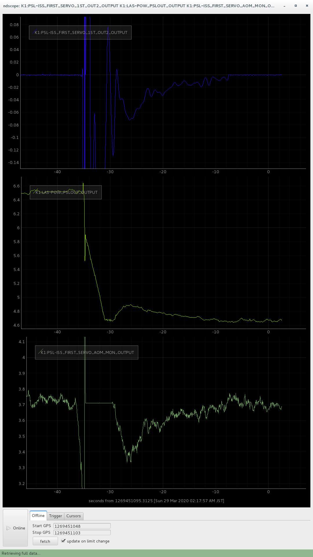
ISS has been modified. ISS can be locked within 30 sec after lock-loss. However, it cannot follow the PSL power change. So, we should engage the ISS after the powering up.
- I changed the error point of the DC cut-off loop from AOM output to the error point (FIRST_SERVO_1ST_OUT2) and engaged the loop all the time. We don't need any zeroing state in the guardian. The UGF of this loop is below 0.1 Hz.
- I also implemented the AOM output loop which fixes the AOM output to the setpoint. The UGF of this loop is below 0.1 Hz. This will be disabled after the integrator got engaged.
- The attached figure shows the time series of the error signal (top), PSL output power (mid), and AOM output(bottom). As shown in the figure, the ISS recover the lock within 20 seconds.
- I modified the guardian also. I tried several lock-loss and the guardian could recover the ISS with a 100 % success rate.
- However, I'm not sure about the long term stability. I might need another zero-pole for AC-coupled ISS.
- I also implemented gain normalization with the IMC output power.
-


![[before the cleaning]](https://klog.icrr.u-tokyo.ac.jp/osl/uploads/29414_1715068196_IMG_3745.jpg)
![[after the cleaning]](https://klog.icrr.u-tokyo.ac.jp/osl/uploads/29414_1715068200_IMG_3747.jpg)
I found one problem of the new control scheme. If there is the offset between the error point and the monitor point, actual error signal cannot be zero. And due to the integrator, the AOM output will drift due to that offset.
I put new path named DRIFT_COMP from the AOM output to the error point of the DC cut loop. It seems to be working fine for several minutes. Let's see the long term stability.
And we might not need the AOM output loop anymore. At some point, I will remove it.
ISS continued to be locked for more than 1 hour with integrator. Drift compensation servo seems to work well.
I modified the ISS model to implement the DC cut loop. The detail would be reported by Miyakawa-san.
I put new filter named as K1:PSL-ISS_FIRST_SERVO_DC_CUT_FILT.