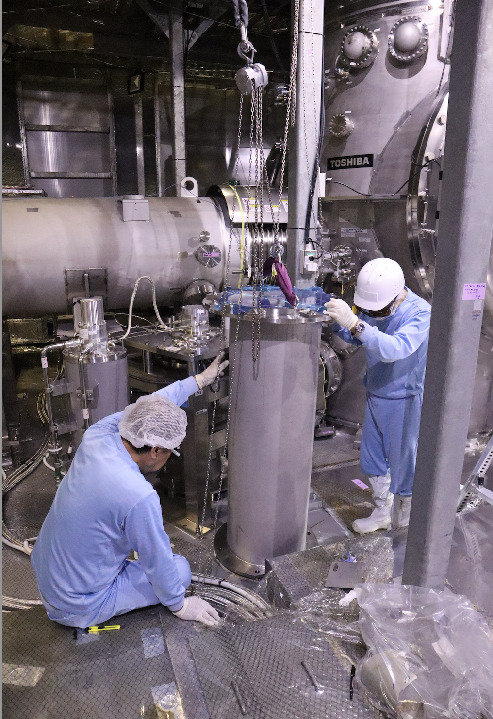
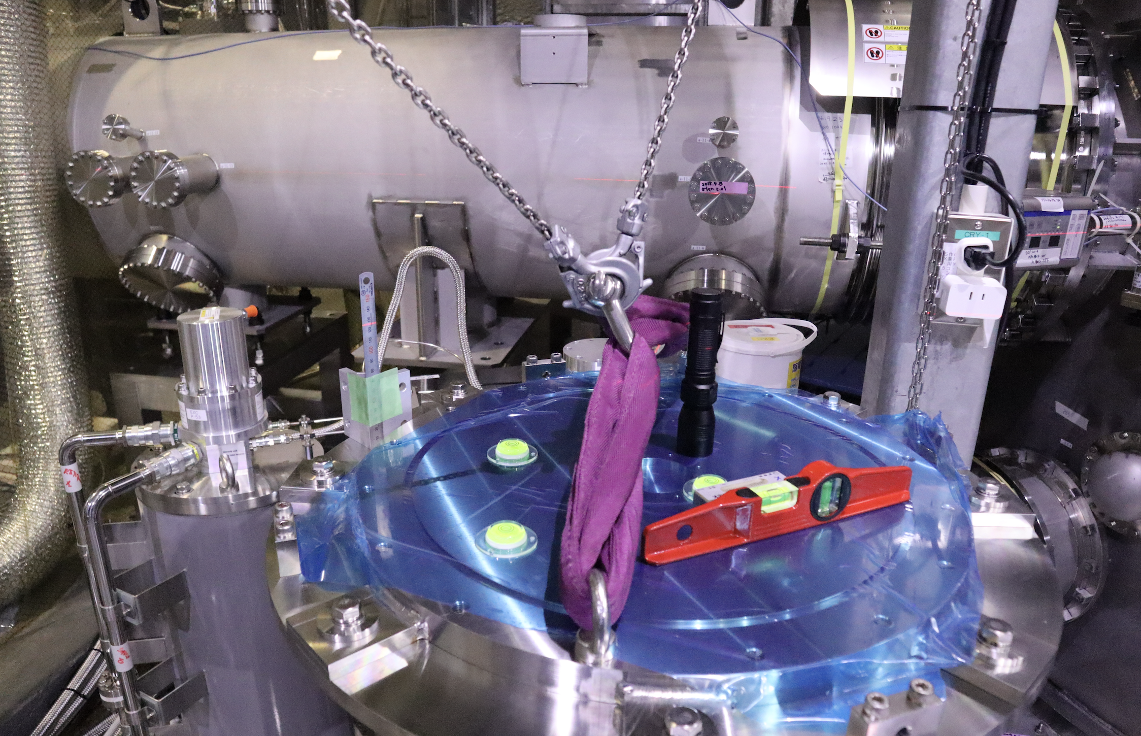
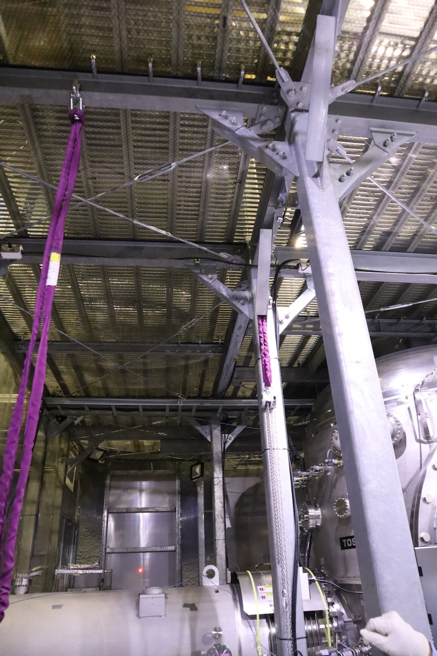
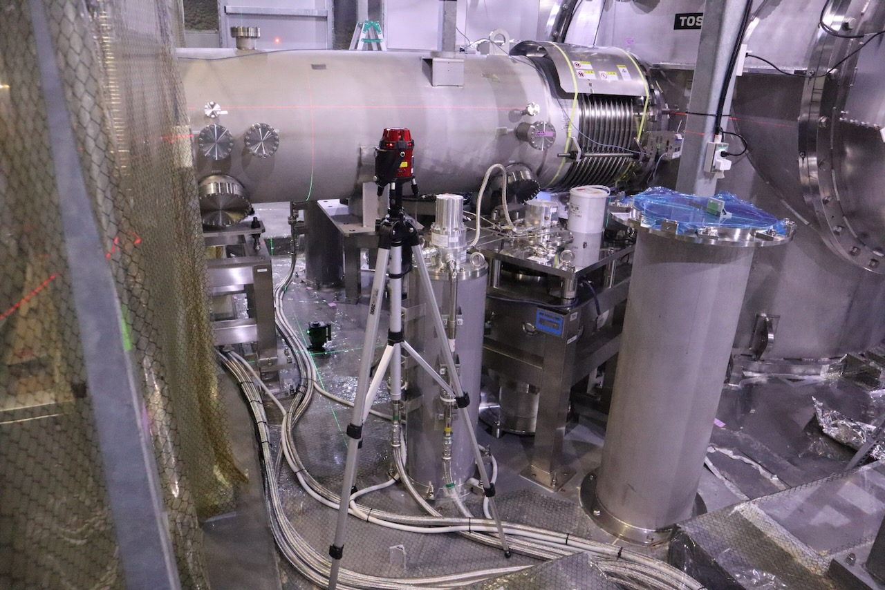
We try install Ncal Pylon @ Xend Y-minus.
We roughly tune high and inclination of NCal pylon using sims.
We didn't finish the work, so We will continue tomorrow.


Details of the NCal pylon installation
Before starting the installation, we transported the required tools and equipment from the central area to Xend, including a steel ruler, a laser level, slings, and a chain block. We also removed the floor mat in the anteroom of the EXC clean booth and cleaned the floor.
One NCal pylon was moved today. In front of the C-chamber anteroom, the pylon was lifted from its pallet using a tripod and placed on a Bishamon lift table. It was then transported into the anteroom. The protective plastic covering was removed, and both the pylon and the lift table were carefully wiped and cleaned.
Inside the clean area, we moved a workbench that had been located between the anteroom and the installation position. We used some C-clamps, slings, and chain blocks to a beam of the clean booth, and slings and chain blocks were connected to it. The pylon was then moved into the clean booth.
At the installation position, we removed the tape covering the anchor holes and cleaned the area. We also removed the waterproof sheet. We found that there is a boundary or gap in the floor near the installation position, which needs to be considered carefully when adjusting the balance of the pylon.
The pylon was suspended from two directions and moved above the installation position. Shim plates equivalent to those used under the cryocoolers in the cryogenic area were inserted between the floor and the pylon to adjust the inclination.
During this work, we found that the prepared M16 bolts were too long, and therefore the pylon could not be completely fixed to the floor. At present, the pylon is temporarily held by the long bolts and the lifting equipment.
Height and inclination adjustment
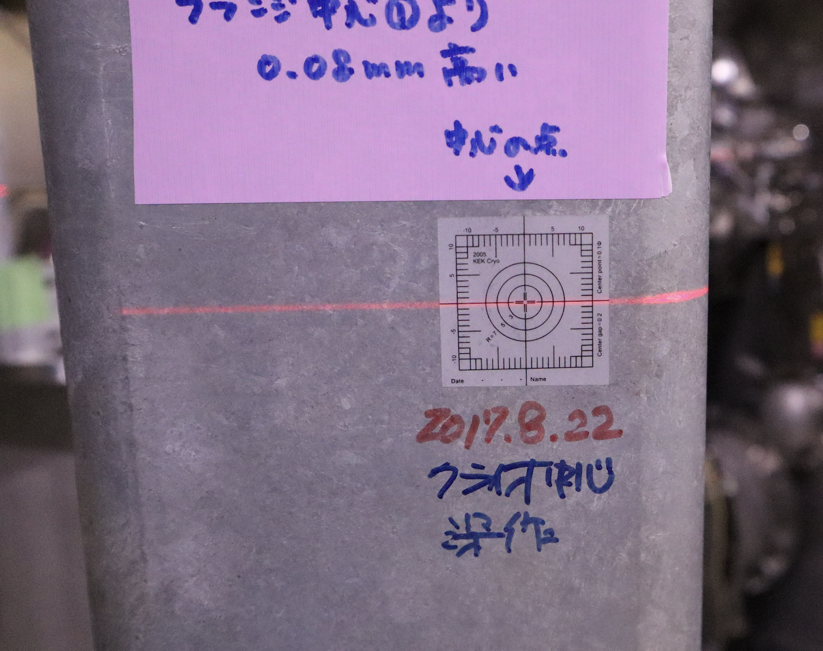
The pylon height and inclination were adjusted using a laser level. The reference height was the mark labeled “Cryogenic center,” which was created on August 22, 2017, and reconfirmed on May 3, 2021. We also confirmed that this reference point is approximately consistent with the center of the arm pipe.
This reference point appears to be the one described in klog16644. According to that klog, ETMX was located 8.5 mm below this reference height. However, we have not yet checked whether this relation was modified in later work. For the NCal installation, the important quantity is not simply matching the ETMX height, but accurately determining the relative position between the NCal and ETMX.
A steel ruler was placed on the 640-mm-diameter intermediate positioning plate on top of the pylon. The laser height was measured at four positions corresponding to the (-y), (+x), (+y), and (-x) sides relative to the pylon center.
The final ruler readings today were:
(-y, +x, +y, -x) = (127.5, 127.5, 126.0, 126.0) mm.
Assuming that ETMX is located at the reference height, the nominal design value is approximately 125 mm. However, future fine height adjustment is planned to be performed using shim plates underneath the NCal unit itself rather than underneath the pylon. Therefore, we decided to keep the current readings slightly larger than 125 mm.
Remaining work
- Replace the currently used M16 bolts with shorter bolts. Suitable shorter M16 bolts were found in the central area.
- Replace the current shim plates, whose lateral dimensions are too large, with smaller shim plates. Suitable plates were also prepared in the central area.
- Complete the fixing and alignment of this pylon.
- Install the second pylon on the (+y) side.
The work was not completed today and will continue tomorrow.
Pictures will appear here: link

I have not found any later klog entries describing further changes to its height.
In klog 20036 describes an attempt to identify the center of the test mass using TCam images. By applying a similar method, it may be possible to estimate the current position of the test mass by comparing its position relative to stationary objects visible in both the TCam images taken around the time of klog 16535 and the current TCam images.
Replacement of the Shim Plates for the Y_minus Pylon and Rough Measurements in the x and y Directions
klog 37274 and klog 37276 describe the installation of the Y_minus pylon. This report describes the work performed after the pylon was installed in the condition documented in those klog entries.
Replacement of the Shim Plates
The shim plates used during the work described in klog 37274 and klog 37276 were too large and protruded beyond the base of the pylon. Therefore, the pylon was lifted again, and the existing shim plates were replaced with smaller ones.
Measurement of the Pylon Height
After replacing the shim plates, the height of the pylon was measured. The reference height used for this measurement appears to be the one described in klog 16644. According to that klog entry, ETMX was located 8.5 mm below this reference height. However, we have not yet confirmed whether this relationship was modified during subsequent work.
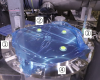
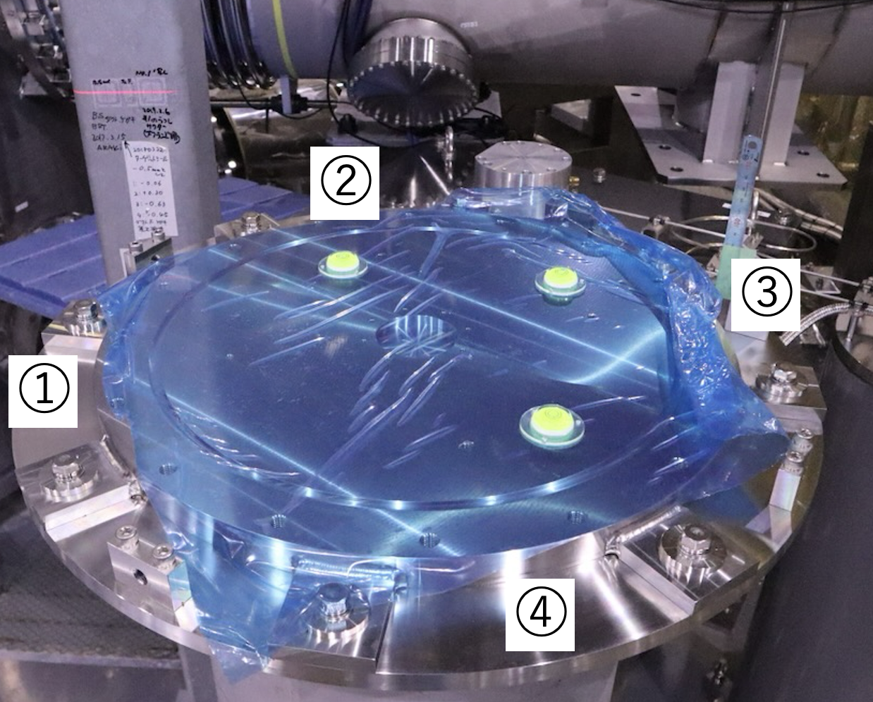
A laser level was used to establish a horizontal reference plane. The four measurement points were labeled ①–④, as shown in the photograph. The positions of the laser line on the scale were as follows:
(①, ②, ③, ④) = (127.5, 127.5, 126.5, 127.0) mm
Rough Measurements in the x and y Directions
Rough measurements were performed to check whether the pylon had been installed approximately at its design position.
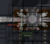
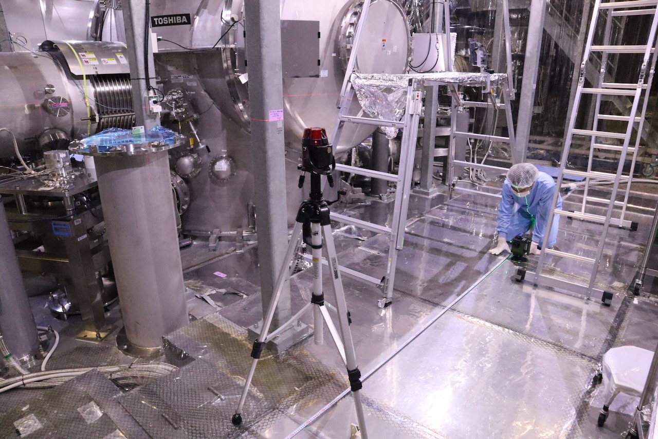
The C chamber has a marker indicating its center, together with lines extending from the center in the L and T directions. A laser level was aligned with these markings to establish the chamber centerlines. A second laser level was then used to transfer the reference lines to the pylon location. The reference lines were transferred by aligning the laser lines from the two laser levels so that they overlapped.
The distance between the two laser levels was measured using a tape measure. A scale was placed at the center of the bottom surface of the NCal vacuum chamber installed on the pylon, and the position of the laser line on the scale was recorded.
The center of the bottom surface of the NCal vacuum chamber was assumed to correspond to the center of the pylon. Based on this assumption, the measured distance from the L-direction centerline to the pylon center was 2240 mm, and that from the T-direction centerline was 1865.5 mm.