[Tanaka, Fujimoto, Saito]
When the LO frequency was adjusted relative to the beat frequency so that the error signal became close to 0 V, it was found that the beat frequency and LO frequency matched at higher frequencies, whereas an offset appeared at lower frequencies. Next, in order to achieve locking using only the SR560, the SR560 was configured as a first-order low-pass filter with a cutoff frequency of 1 Hz and a gain of 200. Under this condition, locking was successfully achieved. Measurement of the open-loop transfer function showed that the UGF was approximately 17 Hz. Next, we attempted to use the FM modulation function of the LO source (Keysight E8663D) in order to sweep the LO frequency and scan the SRY. However, the FM modulation option was not installed. Therefore, the function generator of the Moku:Lab was used instead. When the frequency modulation was performed at a rate of 1 Hz, no SRY flashes were observed on the OMC REFL PD. This is likely because the frequency modulation was carried out at 1 Hz, whereas the cutoff frequency of the high-pass filter in the SR560 used for the OMC REFL PD signal was 300 Hz. Therefore, the cutoff frequency was lowered to 100 Hz, but the main-laser noise became comparable to the amplitude of the sub-laser flashes, so the cutoff frequency was restored to 300 Hz. In addition, increasing the frequency modulation rate of the LO caused the beat signal waveform to become distorted.
-
First, the LO frequency was adjusted relative to the beat frequency so that the error signal became close to 0 V. The resulting frequencies were as follows:
Beat frequency LO frequency
33 MHz 54 MHz
78 MHz 85 MHz
139 MHz 139 MHz
179 MHz 179 MHzTherefore, at higher frequencies there appears to be no offset, and the beat frequency matches the LO frequency. Furthermore, at lower frequencies, the beat signal and LO signal were directly observed using the Moku:Lab oscilloscope. The measured beat frequency agreed with the frequency observed on the Moku:Lab spectrum analyzer after the signal had been split by the power splitter, and the LO frequency agreed with the set value. Therefore, the observed offset appears to originate from the PFD.
-
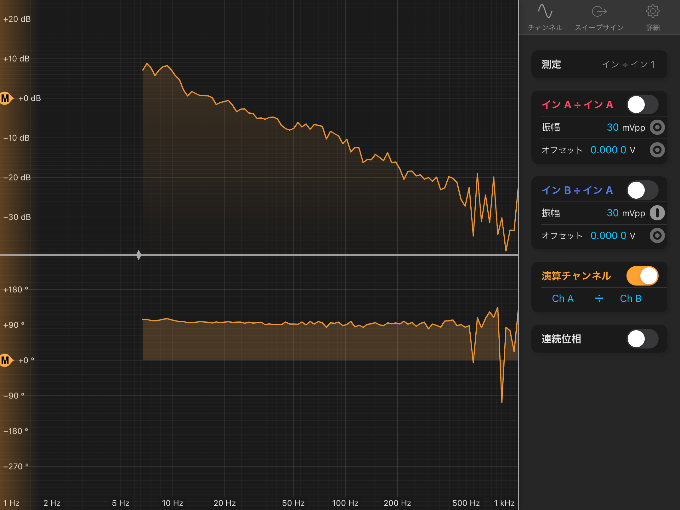
Next, a DC voltage was applied to the SR560 to determine its allowable input and output voltage ranges before overload occurred. The maximum allowable input voltage was found to be 2 V, while the maximum output voltage was 5 V. When the error signal was near 0 V, observation of the error signal with a 100 kHz low-pass filter showed fluctuations of approximately 4 Vpp. Therefore, a 20 dB attenuator was inserted to ensure that the signal could be safely input to the SR560. Furthermore, when the error signal was 150 mV, the beat frequency and LO frequency differed by approximately 10 MHz, corresponding to a sensing efficiency of approximately 15 nV/Hz. To achieve locking using only the SR560, the SR560 was configured as a first-order low-pass filter with a cutoff frequency of 1 Hz and a gain of 200, and stable locking was achieved. The current control loop from the RFPD output to the sub-laser PZT is as follows:
RFPD→ 12 MHz high-pass filter→ 20 dB RF amplifier→ 45 dB RF amplifier→ 10 dB attenuator→ PFD→ 20 dB attenuator→ 100 kHz low-pass filter→ SR560 (1 Hz cutoff frequency, gain ×200, first-order low-pass filter)→ Sub-laser PZT
The open-loop transfer function was then measured, yielding a UGF of approximately 17 Hz (Fig. 1).
-
Next, in order to scan the SRY by sweeping the LO frequency, we attempted to use the FM modulation function of the LO source (Keysight E8663D). However, this option was not installed. Therefore, a 1 Vpp sinusoidal signal was generated using the Moku:Lab function generator and used as the LO signal. The LO frequency was first matched to the beat frequency and then frequency-modulated by ±2 MHz at a modulation rate of 1 Hz (Fig. 2). However, no SRY flashes were observed on the OMC REFL PD. This is likely because the modulation rate of 1 Hz is below the 300 Hz cutoff frequency of the high-pass filter in the SR560 used for the OMC REFL PD signal. The cutoff frequency was therefore reduced to 100 Hz, but the main-laser noise became comparable in magnitude to the sub-laser flash signal, so the cutoff frequency was returned to 300 Hz. The dominant main-laser noise frequency was approximately 60 Hz. In addition, the frequency modulation rate of the LO was increased, but the shape of the beat signal became distorted.


