Reports 1-1 of 1 Clear search Modify search
MIF (General)
shun.saito - 2:15 Thursday 18 June 2026 (37086) Print this report
Modification of the optical layout following the addition of a lens before the FI

[Smith, Tanaka, Hirose, Fujimoto, Saito]

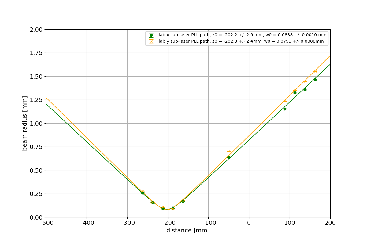
The mount of a mirror located near the BS was found to be malfunctioning, so it was replaced. As a result, this mirror can now be used for alignment. The power of the main laser incident on the PLL RFPD was measured and found to have increased from approximately 19 μW (klog:37020) before the BS was replaced with a mirror in klog:37058 to approximately 69 μW. Mirrors and lenses were then installed according to the redesigned optical layout. In the PLL path, the mode-matching ratio between the main laser and the sub-laser was found to be approximately 33%. This is due to a mismatch in the waist positions. If the waist positions are matched, the mode-matching ratio is expected to improve to approximately 94%. Therefore, we plan to modify the sub-laser optical path length after the 50 mm focal-length lens. The mode-matching ratio for the optical path that injects the sub-laser into the interferometer will be evaluated in the next measurement.


  • The mirror located near the BS, which is the last mirror encountered by the sub-laser before entering the interferometer, had a faulty mount, making alignment using this mirror impossible. Therefore, the mount was replaced. Before the replacement, the alignment of the PLL optical path was adjusted so that the DC signal at the RFPD was maximized. After replacing the mount, alignment was performed using only this mirror, again maximizing the DC signal at the RFPD.
     
  • The power of the main laser incident on the RFPD was then measured. Before the BS was replaced with a mirror in klog:37058, the power was approximately 19 μW (klog:37020), whereas it is now approximately 69 μW.
     
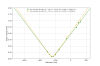
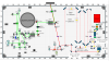
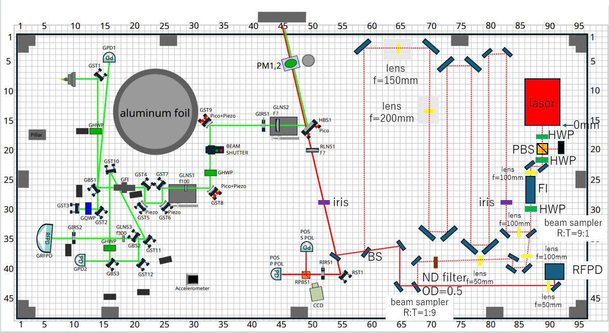
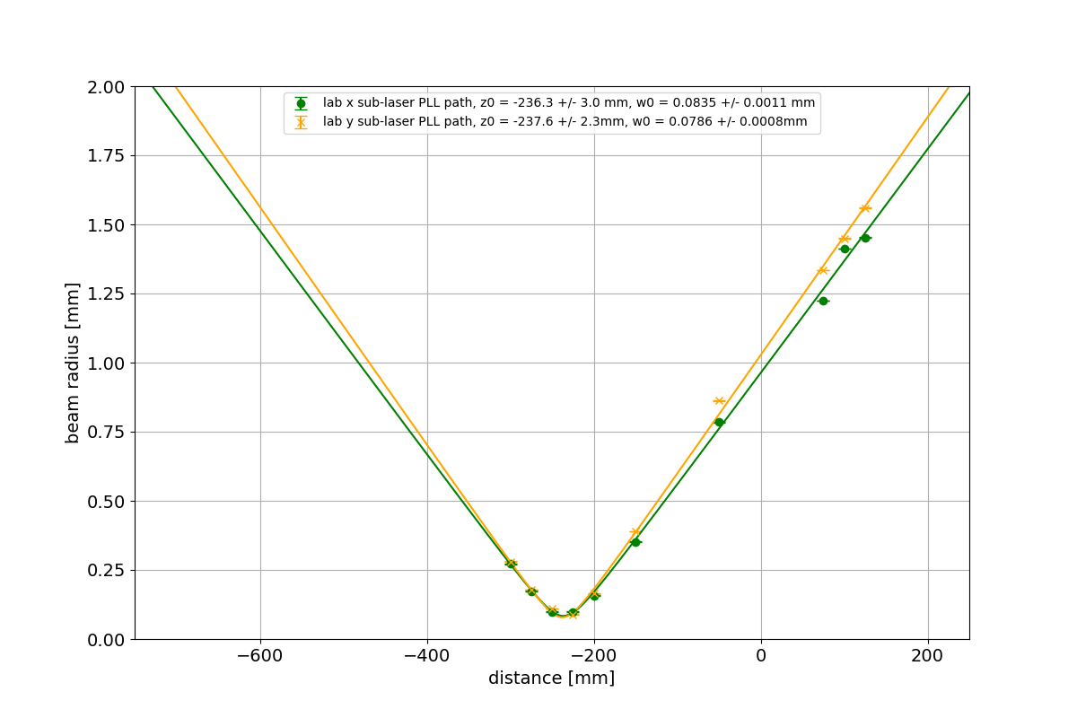
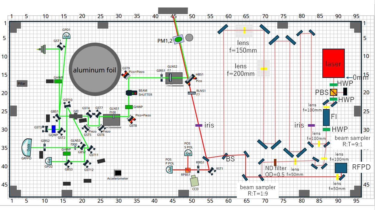
  • Next, the mirrors and lenses used in the PLL optical path were reinstalled according to the redesigned optical layout (Fig. 1). The beam profile was measured after the 50 mm focal-length lens and fitted (Fig. 2). The waist positions and waist radii obtained from the fitting are listed below. The coordinate origin is defined at the beam sampler (R:T = 1:9) where the main-laser and sub-laser beams are combined.

    Sub-laser

    x direction: Waist position= −236.3 ± 3.0 mm, Waist radius= 0.0835 ± 0.0011 mm
    y direction: Waist position= −237.6 ± 2.3 mm, Waist radius= 0.0786 ± 0.0008 mm
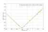
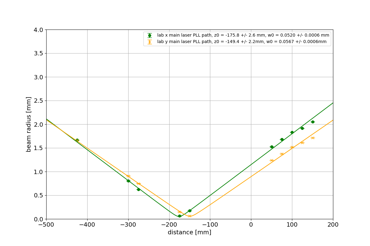
    →Average: Waist position= −237 mm, Waist radius= 0.081 mm

    For comparison, the beam-profile results of the main laser from klog:37020 were used:

    Main laser

    x direction: Waist position= −220.1 ± 3.7 mm, Waist radius= 0.0577 ± 0.0006 mm
    y direction: Waist position= −170.7 ± 7.6 mm, Waist radius= 0.0674 ± 0.0014 mm
    →Average: Waist position= −195.4 mm, Waist radius= 0.0626 mm

    Using these results, the mode-matching ratio was calculated to be approximately 33%. Since the waist positions differ by 41.5 mm, the beam sampler (R:T = 1:9), where the main and sub-laser beams are combined, needs to be moved 20.8 mm to the right in Fig. 1. If the waist positions are perfectly matched, the mode-matching ratio is expected to improve to approximately 94%. In addition, one of the mirrors in the main-laser optical path was moved slightly relative to its position in klog:37020. Therefore, before moving the beam sampler (R:T = 1:9), we plan to remeasure the beam profile of the main laser and determine the required adjustment based on the new measurement results. Once the mode-matching ratio has been improved, the beat signal will be investigated again.
     

  • Finally, based on the optical layout shown in Fig. 1, four additional mirrors were installed to increase the optical path length of the sub-laser beam directed toward the interferometer. As a result, the 200 mm and 150 mm focal-length lenses require little or no repositioning. In the next measurement, beam profiles will be measured both before and after the waist to confirm whether the waist position is correct. If satisfactory mode matching is achieved, alignment of the sub-laser beam into the interferometer will then be performed.

Images attached to this report
Comments to this report:
shun.saito - 1:47 Friday 19 June 2026 (37093) Print this report

[Ushiba, Tanaka, Hirose, Fujimoto, Saito]

In the PLL optical path, the beam sampler (R:T = 1:9), where the main-laser and sub-laser beams are combined, was moved to match the waist positions of the two beams. As a result, the mode-matching ratio improved to approximately 85%. After aligning the PLL optical path, a beat signal was successfully observed. In the optical path that injects the sub-laser into the interferometer, a beam profiler was placed at the expected beam-waist location, and the lens positions were adjusted so that the waist occurred at that location. When the beam profile was examined from upstream toward the waist, the beam initially had a reasonably clean shape, but gradually became distorted into a vortex-like pattern. Around the waist position, however, the beam profile became clean again. Although the cause of this behavior remains unclear, the beam shape at the point where it enters the interferometer was clean, so we decided to proceed with alignment. After alignment, we attempted to observe flashes from the SRC, but none were detected. This was likely because the main laser was not properly aligned to the SRC. In the next experiment, we plan to realign the system and attempt to observe the flashes again.
 

  • First, the beam profile of the main laser in the PLL optical path was measured and fitted (Fig. 1). The waist positions and waist radii obtained from the fitting are listed below. The coordinate origin is defined at the beam sampler (R:T = 1:9), where the main-laser and sub-laser beams are combined.

    Main laser

    x direction: Waist position = −175.8 ± 2.6 mm, Waist radius = 0.0520 ± 0.0006 mm
    y direction: Waist position = −149.4 ± 2.2 mm, Waist radius = 0.0567 ± 0.0006 mm
    → Average: Waist position = −163 mm, Waist radius = 0.0544 mm

    Comparing these results with the sub-laser waist position measured previously (klog:37086), the waist positions differed by approximately 74 mm. Therefore, the beam sampler (R:T = 1:9) where the main-laser and sub-laser beams are combined was moved approximately 1.5 holes to the right (Fig. 2). The beam profile of the sub-laser was then measured and fitted (Fig. 3). The resulting waist positions and waist radii are listed below. The coordinate origin is defined at the new position of the beam sampler (R:T = 1:9).

    Sub-laser

    x direction: Waist position = −202.2 ± 2.9 mm, Waist radius = 0.0838 ± 0.0010 mm
    y direction: Waist position = −202.3 ± 2.4 mm, Waist radius = 0.0793 ± 0.0008 mm
    → Average: Waist position = −202 mm, Waist radius = 0.082 mm

    To compare the waist positions of the main and sub-laser beams, the main-laser waist position was shifted by the same amount that the beam sampler was moved (approximately 1.5 holes to the right), yielding an adjusted waist position of −200.5 mm. Based on these results, the mode-matching ratio was calculated to be approximately 85%. Next, two irises were installed, and the alignments of the main and sub-laser beams were adjusted so that both beams passed through them. The RFPD position was then adjusted while only the sub-laser beam was incident on the RFPD, and the mirror immediately before the RFPD was used to maximize the DC signal. When the main-laser beam was also directed onto the RFPD, a beat signal was observed. The alignment of the main laser was then optimized to maximize the beat-signal amplitude.
     

  • Next, in the optical path that injects the sub-laser into the interferometer, a beam profiler was placed at the expected waist location, and the lens positions were adjusted so that the beam waist occurred there. However, the beam profile appeared distorted (Fig. 4). We first considered the possibility that the beam was being clipped somewhere in the optical path. However, no significant power loss was observed between the FI output and the beam waist. All mirrors and lenses downstream of the FI were inspected and adjusted to ensure that no clipping was occurring, but the beam profile remained distorted. The optical surfaces of the mirrors and lenses were also checked and cleaned, but no improvement was observed. Furthermore, the beam profiler was positioned near the waist, and the mirror angles were adjusted while observing the beam profile. The distorted beam shape persisted and merely shifted laterally, suggesting that the distortion was not caused by clipping. When the beam profile was observed while moving from upstream toward the waist, the beam initially appeared reasonably clean, then gradually developed a vortex-like distortion, and finally became clean again around the waist position. Although the cause of this behavior remains unknown, the beam shape at the point where it enters the interferometer was clean, so we decided to proceed with alignment. Regarding mode matching, since the beam waist was adjusted to occur at the intended waist location, the mode matching is expected to be reasonably good. The beam-waist radii were approximately 0.076 mm in the x direction and 0.074 mm in the y direction, corresponding to an average waist radius of approximately 0.075 mm. If the waist positions are matched, the mode-matching ratio is expected to be approximately 90%. Finally, alignment was performed using the two irises, and the main-laser beam was blocked so that only the sub-laser remained in the SRC. We then attempted to observe SRC flashes, but none were detected. However, because the main laser was not aligned to the SRC, the alignment of the sub-laser, which had been adjusted to match the main laser, was likely also incorrect. This is considered the most probable reason why no flashes were observed. In the next experiment, we plan to realign the system and continue searching for SRC flashes.

Images attached to this comment
Non-image files attached to this comment
Search Help
×

Warning

×