[Ushiba, Smith, Hirose, Saito]
The optical layout was slightly modified to make the alignment procedure easier. The beam profile of the sub-laser was measured, and the beam waist position and waist radius were determined. Comparing these values with those of the main laser measured in klog:36730, the mode-matching ratio was estimated to be approximately 89%. In addition, the alignment of the sub-laser beam incident on the SRC was performed using two irises. When the sub-laser PZT was driven, flashes were observed with the OMC REFL PD (K1:OMC-REFL_DC_OUT_DQ). By adjusting one mirror to maximize the signal while the PD gain was set to 40 dB, the maximum signal reached approximately 478 counts. Further improvements in alignment and mode matching are expected to increase the signal to approximately 1700 counts.
-
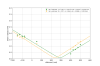
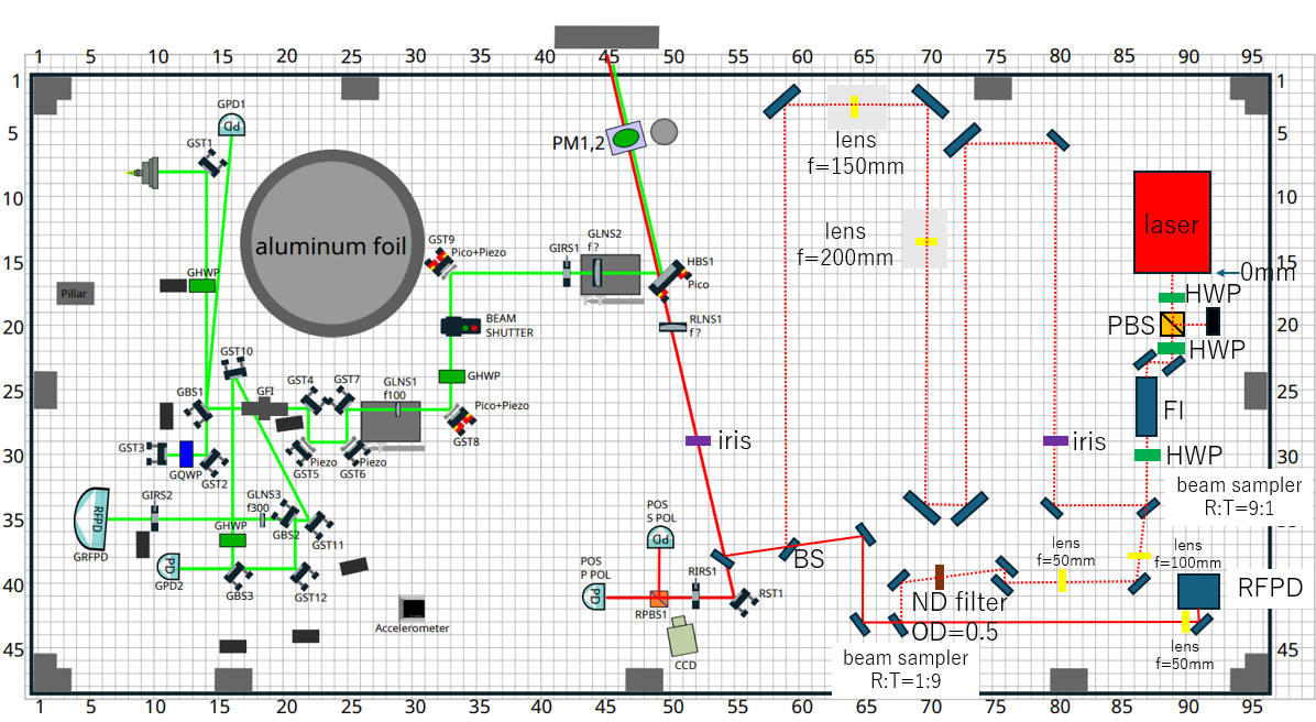
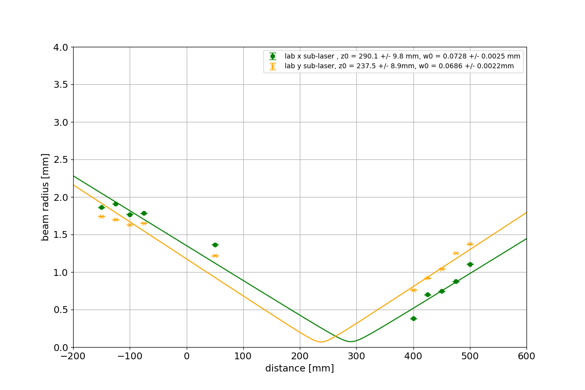
First, the optical layout was modified slightly to facilitate alignment (Figure 1). Using the sub-laser beam, the alignment was adjusted to avoid beam clipping. Next, the beam profile of the sub-laser was measured at locations far from the beam waist using a beam profiler, and a fit was performed (Figure 2). The resulting waist positions and waist radii were as follows:
Sub-laser
x-direction: Waist position = 290.1 ± 9.8 mm, Waist radius = 0.0728 ± 0.0025 mm
y-direction: Waist position = 237.5 ± 8.9 mm, Waist radius = 0.0686 ± 0.0022 mm
→Average: Waist position = 264 mm, Waist radius = 0.071 mmFor comparison, the main-laser beam profile measured in klog:36730 was used. The results were:
Main laser
x-direction: Waist position = 264.3 ± 5.1 mm, Waist radius = 0.0526 ± 0.0025 mm
y-direction: Waist position = 253.6 ± 2.3 mm, Waist radius = 0.0555 ± 0.0013 mm
→Average: Waist position = 259 mm, Waist radius = 0.054 mmUsing these results, the mode-matching ratio was calculated to be approximately 89%.
-
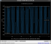
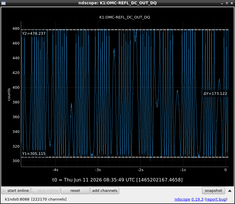
Next, two irises were used to ensure that the optical paths of the main laser and the sub-laser coincided. The alignment was adjusted using the BS and a nearby mirror. The main laser was then blocked so that only the sub-laser beam was present in the SRC. The sub-laser PZT was driven with a sinusoidal signal generated by the Moku:Lab function generator, and the OMC REFL PD (K1:OMC-REFL_DC_OUT_DQ), which had been installed by Tanaka-san(klog:37057), was monitored for flashes. Initially, no flashes were observed. However, after adjusting the mirror associated with the BS, flashes became visible (Figure 3). By adjusting one mirror to maximize the signal, the signal amplitude oscillated between approximately 305 counts and 478 counts.
-
Assuming that the optical power of the sub-laser incident on the SRC is 500 mW, the optical power reaching the OMC REFL PD at resonance is expected to be approximately 16 μW. The responsivity of the OMC REFL PD (Thorlabs PDA100A2) is approximately 680 V/W, and the PD gain was set to 40 dB. Therefore, the output voltage at resonance is expected to be approximately 1.1 V. Using the calibration factor of 610 μV/count, this corresponds to approximately 1700 counts at resonance. Therefore, by using the second mirror to further improve the alignment, the signal should be increased further.


