With Jiahui Xiong
Today, we checked the circuit and cabling for the QPD readout at Pcal-X.
First, we checked the circuit diagram: DocDB 9608 . From the diagram, this circuit seems to provide the 15 V power supply to the PDQ80A and to convert the QPD signals, X, Y, and Sum, from single-ended signals to differential signals.
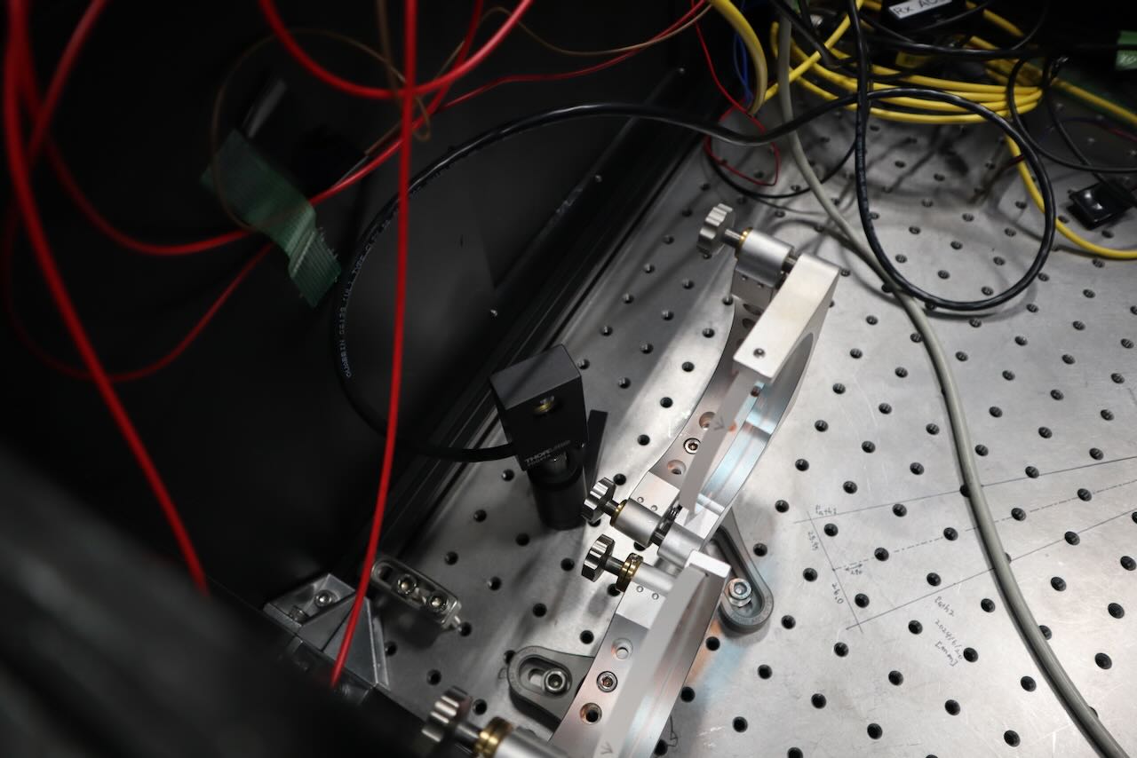
Then we checked the setup at the Pcal-X area, and found the cable connecting the PDQ80A and the D-sub 9-pin connector.
We also tried to check the actual circuit, but it was difficult to remove the cables, so we could not directly inspect the inside of the circuit box.
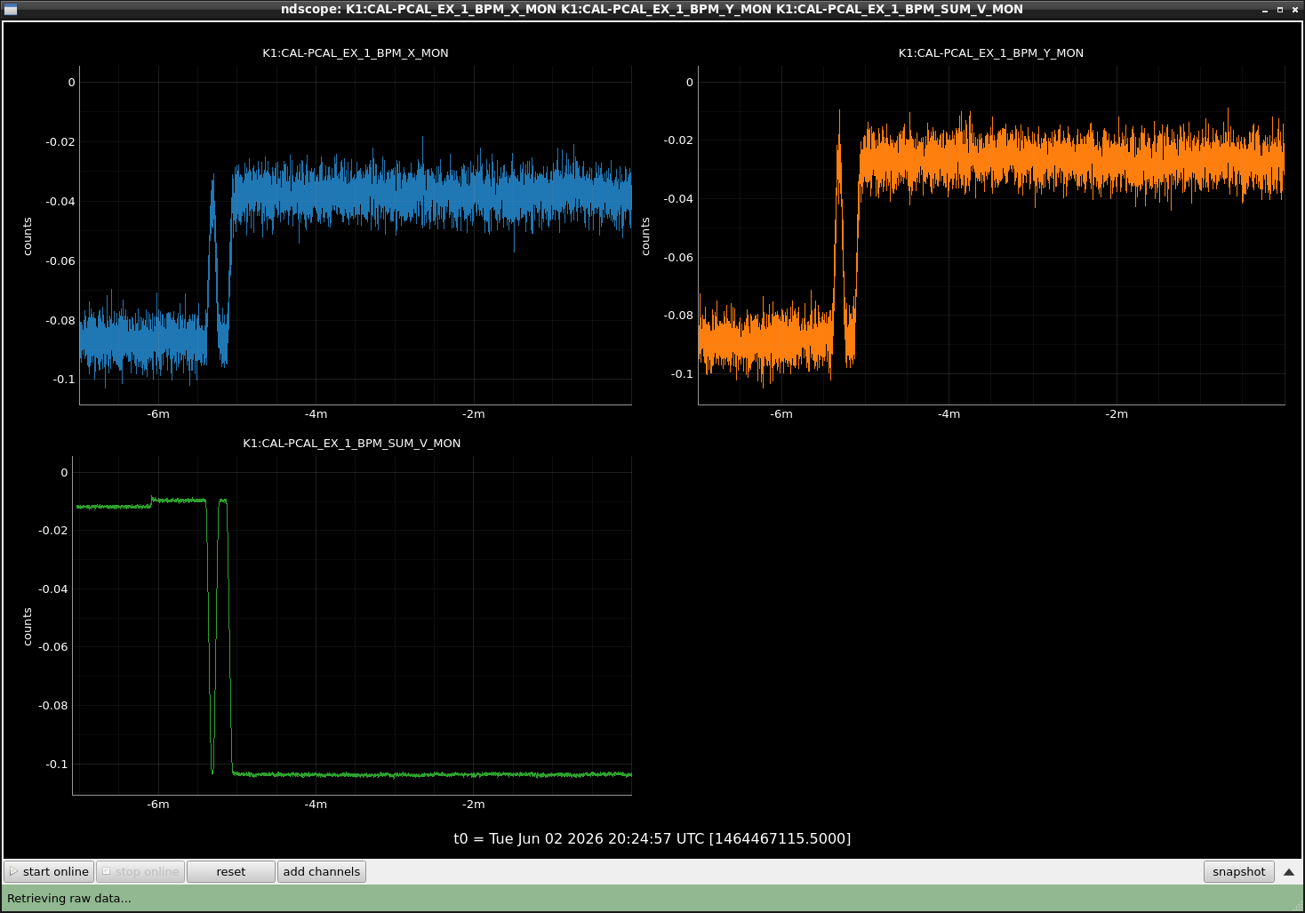
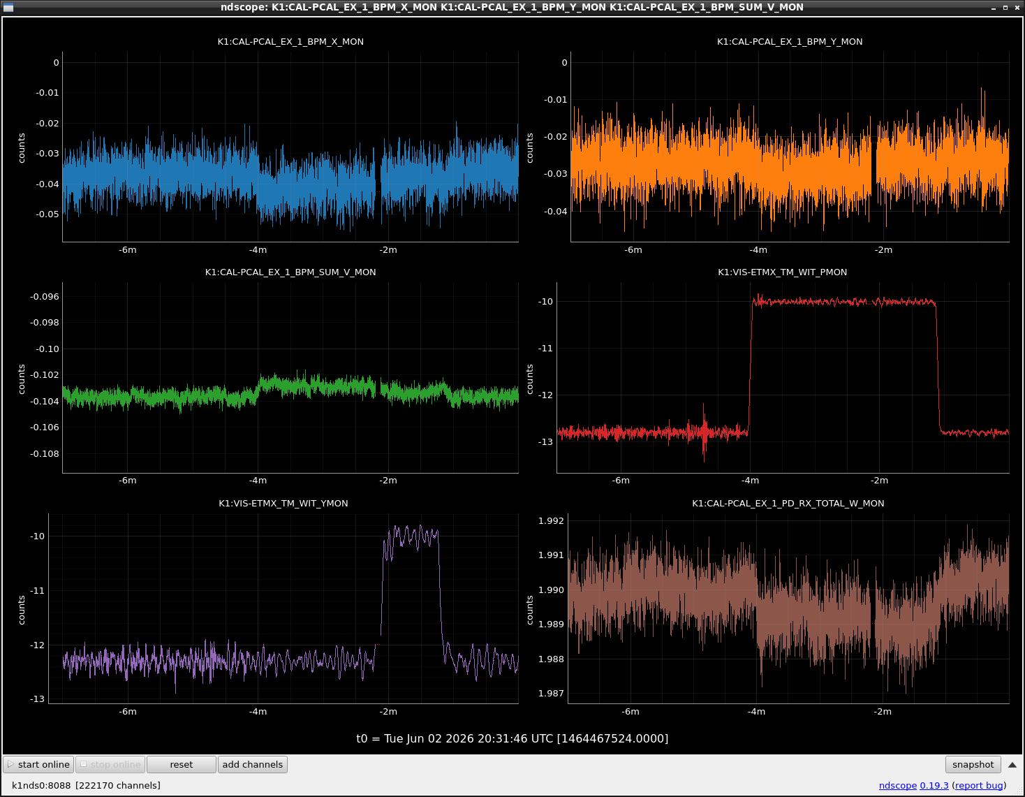
However, after connecting the PDQ80A, we could confirm that the QPD signals were visible in the Pcal real-time model. Therefore, the basic signal readout seems to be working.
Although the alignment was not available today, we fixed one PDQ80A behind the mirror inside the Rx module as a temporary setup.
If possible, we would like to align the ETMX suspension tomorrow morning and adjust the position of QPDs.


