Detail
The first trial
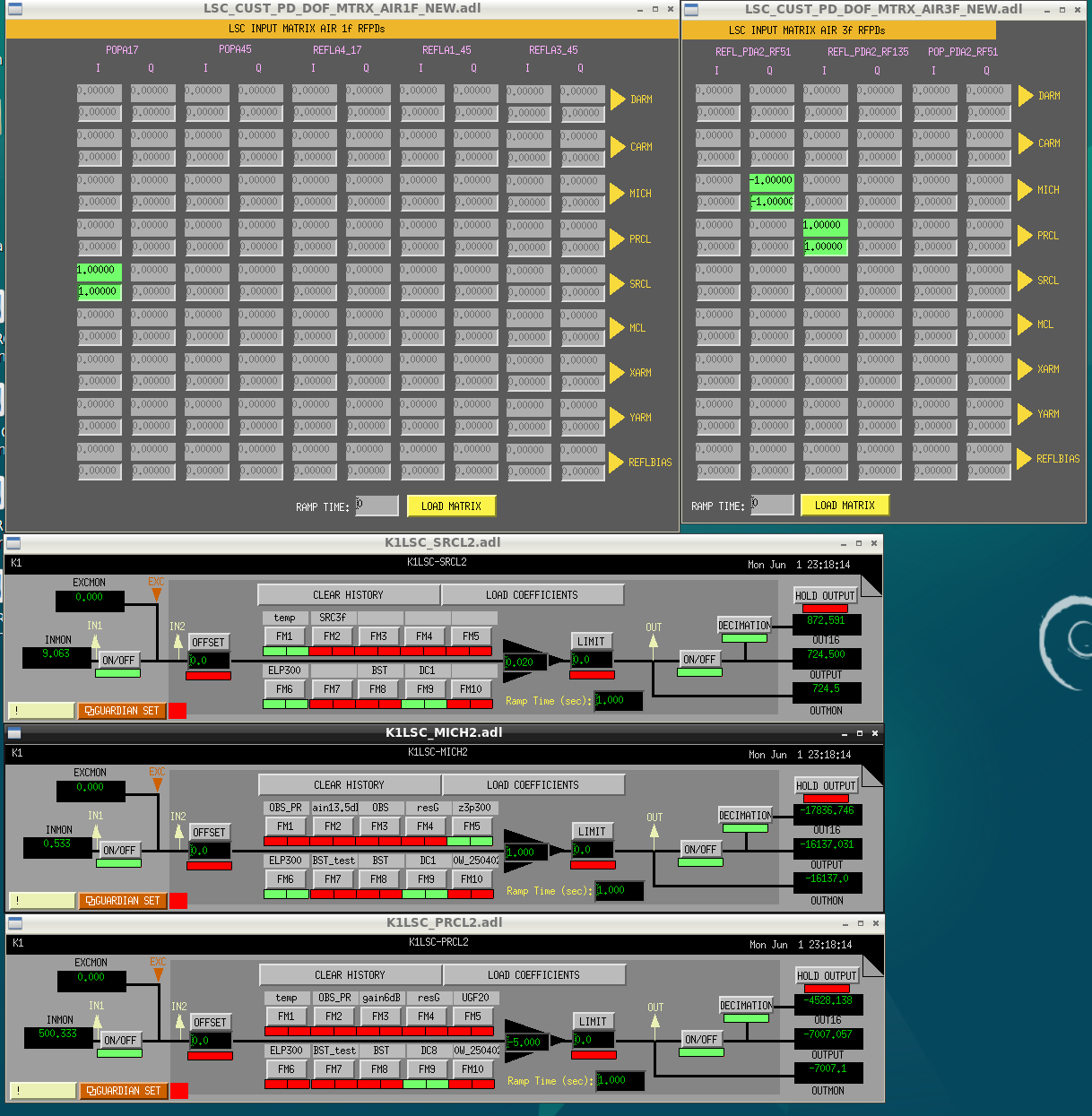
First, we started using 1f signals for locking the DRMI. The signals were as follows:
- PRCL: REFL 45I
- MICHL POP 17Q
- SRCL: POP 17I
The gain settings of them were decided as follows:
- PRCL: Measured the relative gain between REFL 45I and REFL 135I when PRMI was locked using 3f signals. Multiplied the factor by the gain for PRMI 3f locking.
- MICH and SRCL: Estimated the relative gain from SRMI to DRMI using Finesse simulation as shown in Fig. 1 (15 for MICH and -17 for SRCL). Multiplied the factors by the gains for SRMI 1f locking.
The initial guess of the appropriate gains and the actual gains after tuning are as follows:
| DoF | Initial | Tuned |
| PRCL | -0.02 | -0.02 |
| MICH | +20 | +40 |
| SRCL | +0.1 | +0.05 |
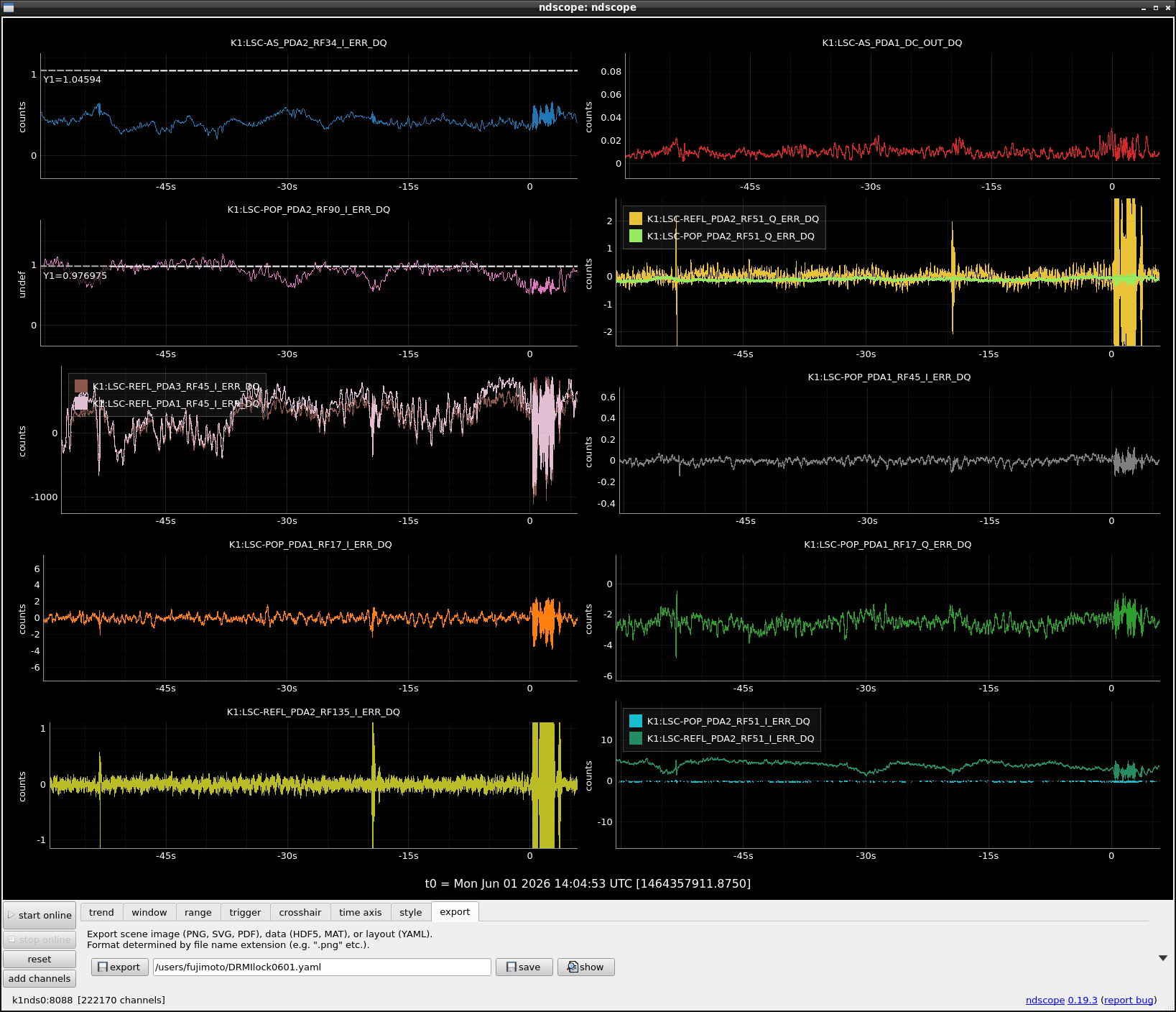
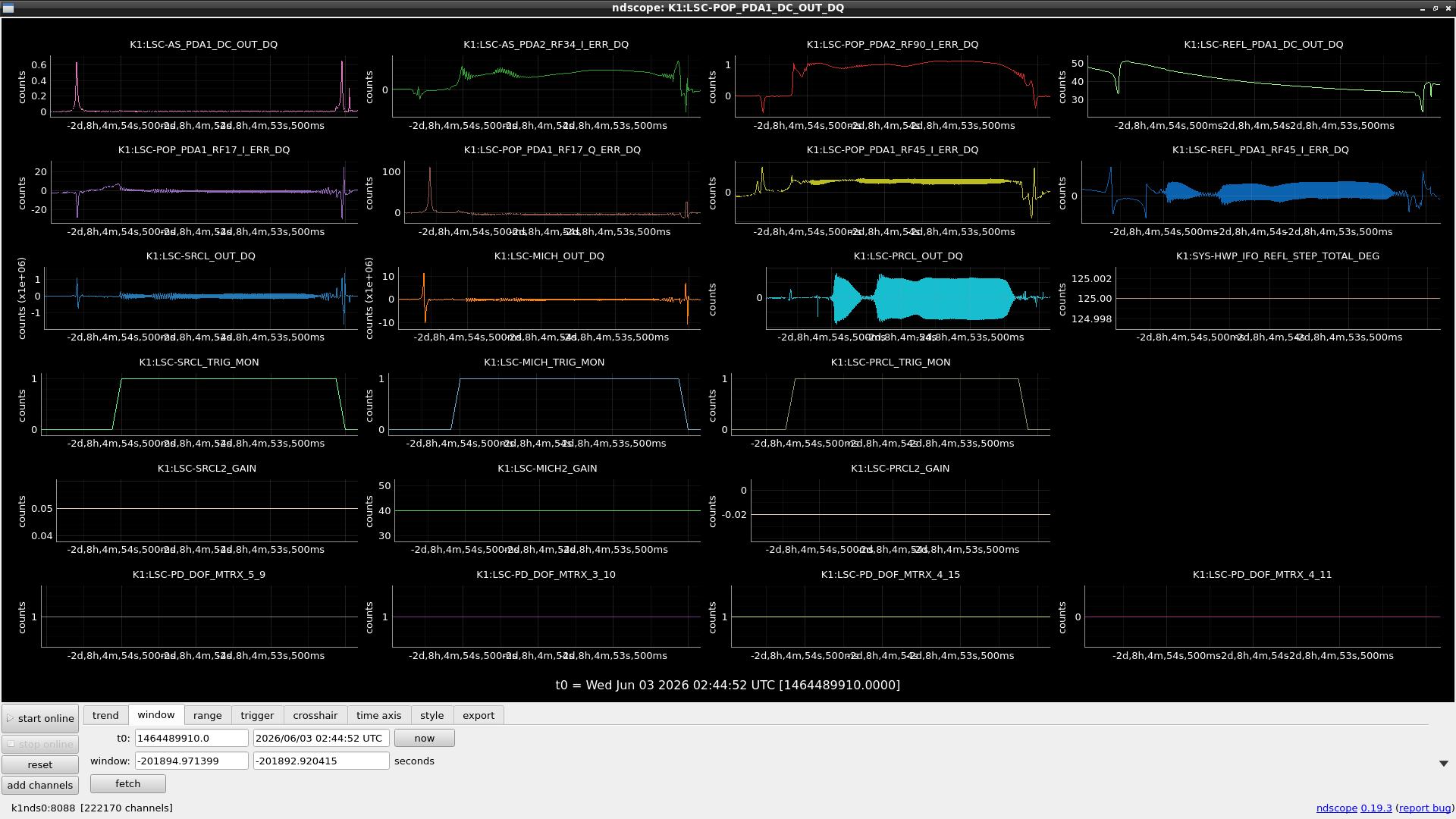
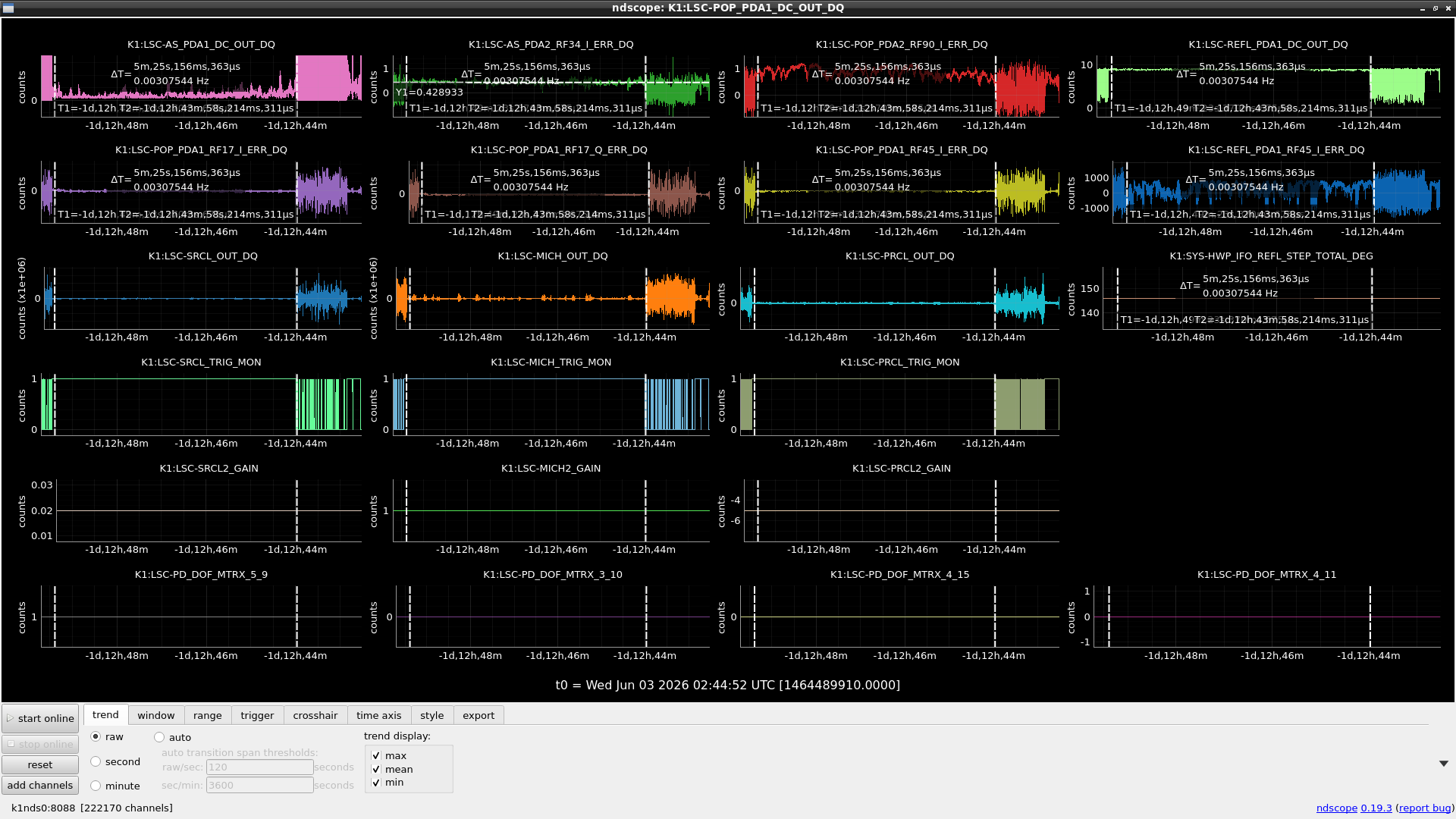
We built these gains beforehand and set triggers to trigger the output when POP90 and AS34 buildups exceeded a certain level. With these configurations, we could hold the interferometer in a good position for ~1 sec (Fig. 1).
Second trial
Next, we changed the PRCL error signal from REFL45I to POP17I, because in RSE, REFL45I is used for CARM and POP17I for PRCL. We tried w/o and w/ triggers, but we could not lock the DRMI, even tweaking the gains. The situation got worse.
We noticed that the PRCL feedback was incredibly small, more than 2 orders of magnitude smaller than the others, so we increased the gain of PRCL, but the stability didn't change significantly. We decided to use REFL135I, which is used for PRMI3f lock, to control PRCL instead of REFL45I. The PRCL gain for the new signal was chosen to maintain the overall gain from POP17I to REFL135I. Soon after changing the signal, we could lock the DRMI in 26 seconds (Fig. 2). Something was wrong with POP17I.
Tuning gains, changing signals
Then we started further tuning of the gains and selecting the signals. We tried replacing POP17Q (1f) with REFL51Q (3f) for MICH control, and it seemed that 3f was better than 1f. We also tried replacing POP17I (1f) with REFL51I (3f) for SRCL control, but in this case, 1f seemed better than 3f.
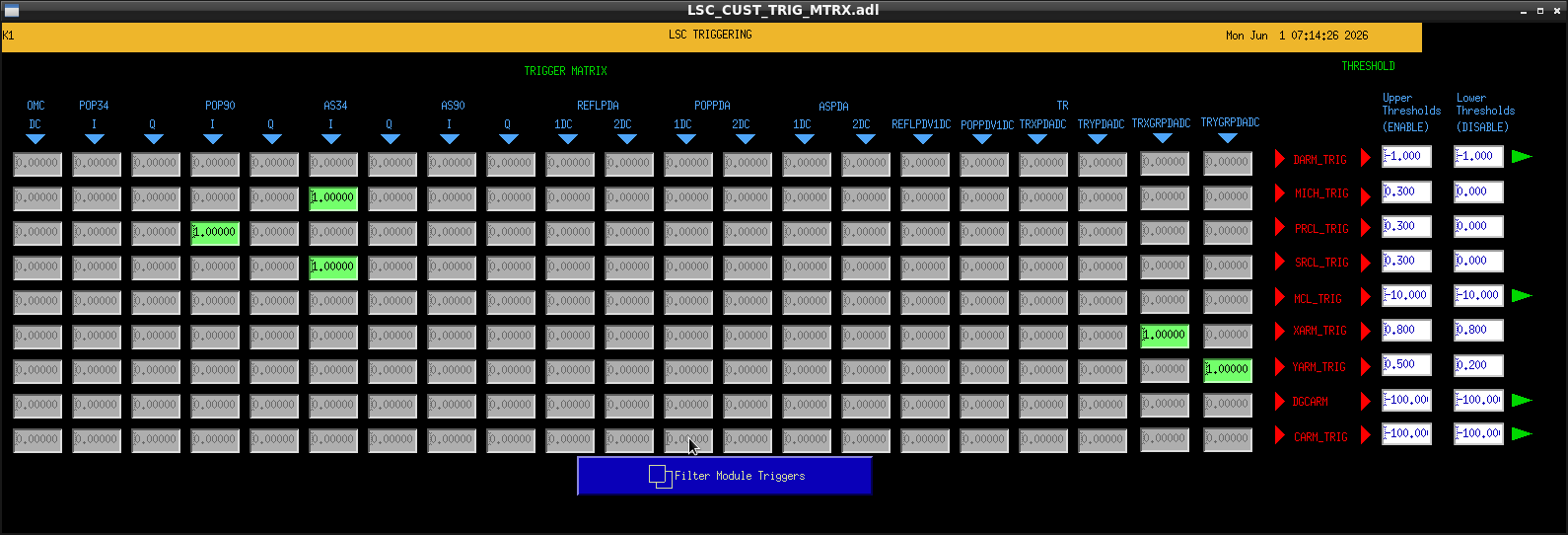
The final configuration of the selected signal, the control gain, and the upper and lower thresholds for each DOF are shown below:
| DoF | Signal | Gain | Upper TH | Lower TH |
| PRCL | REFL135I | -5 | 0.3 | 0 |
| MICH | REFL51Q | 1 | 0.3 | 0 |
| SRCL | POP17I | 0.02 | 0.3 | 0 |
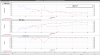
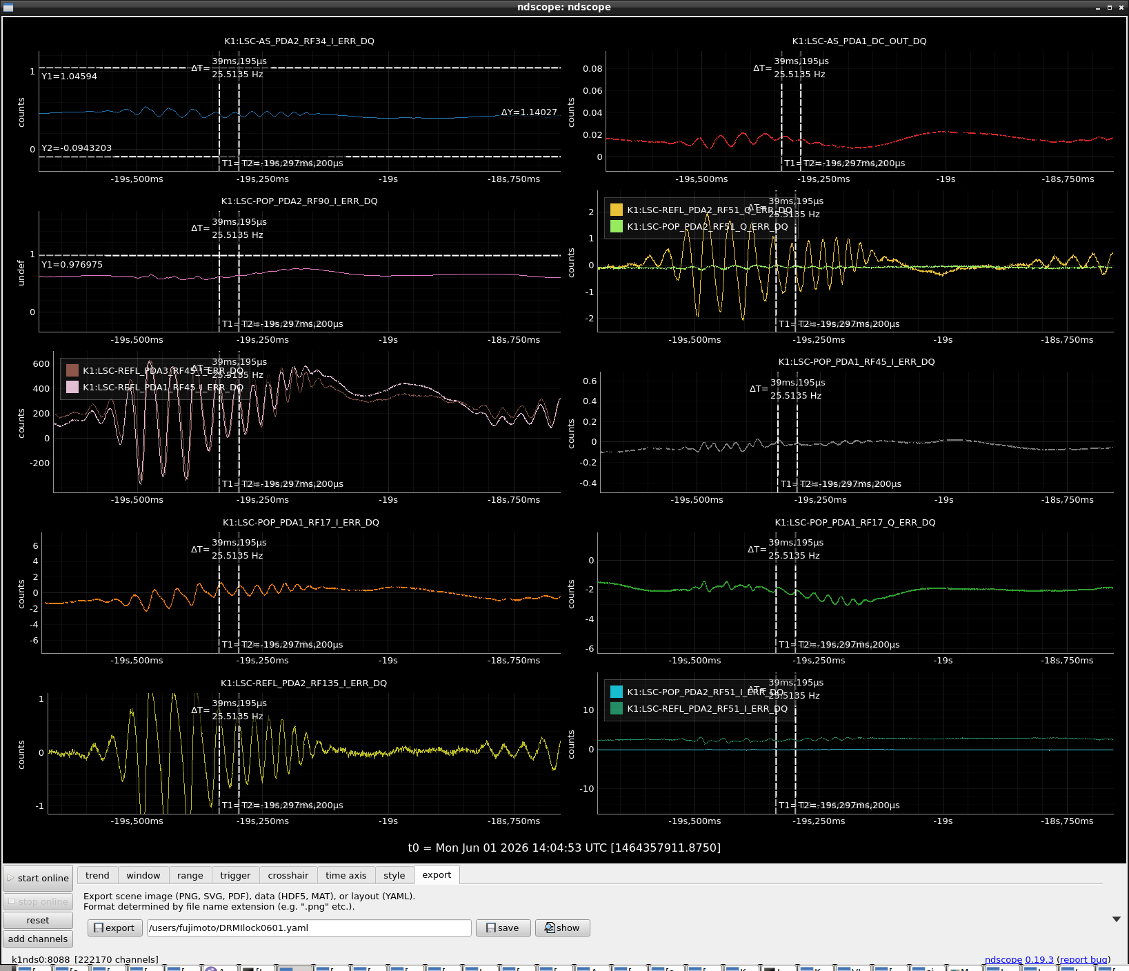
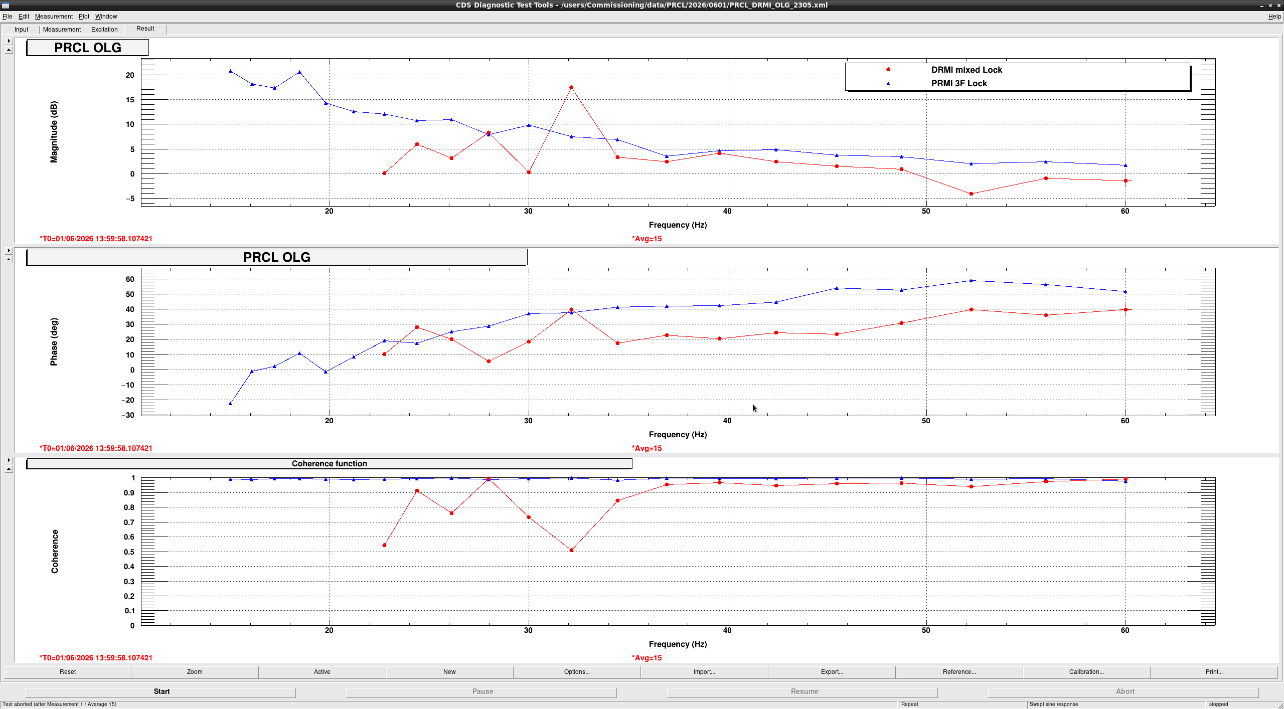
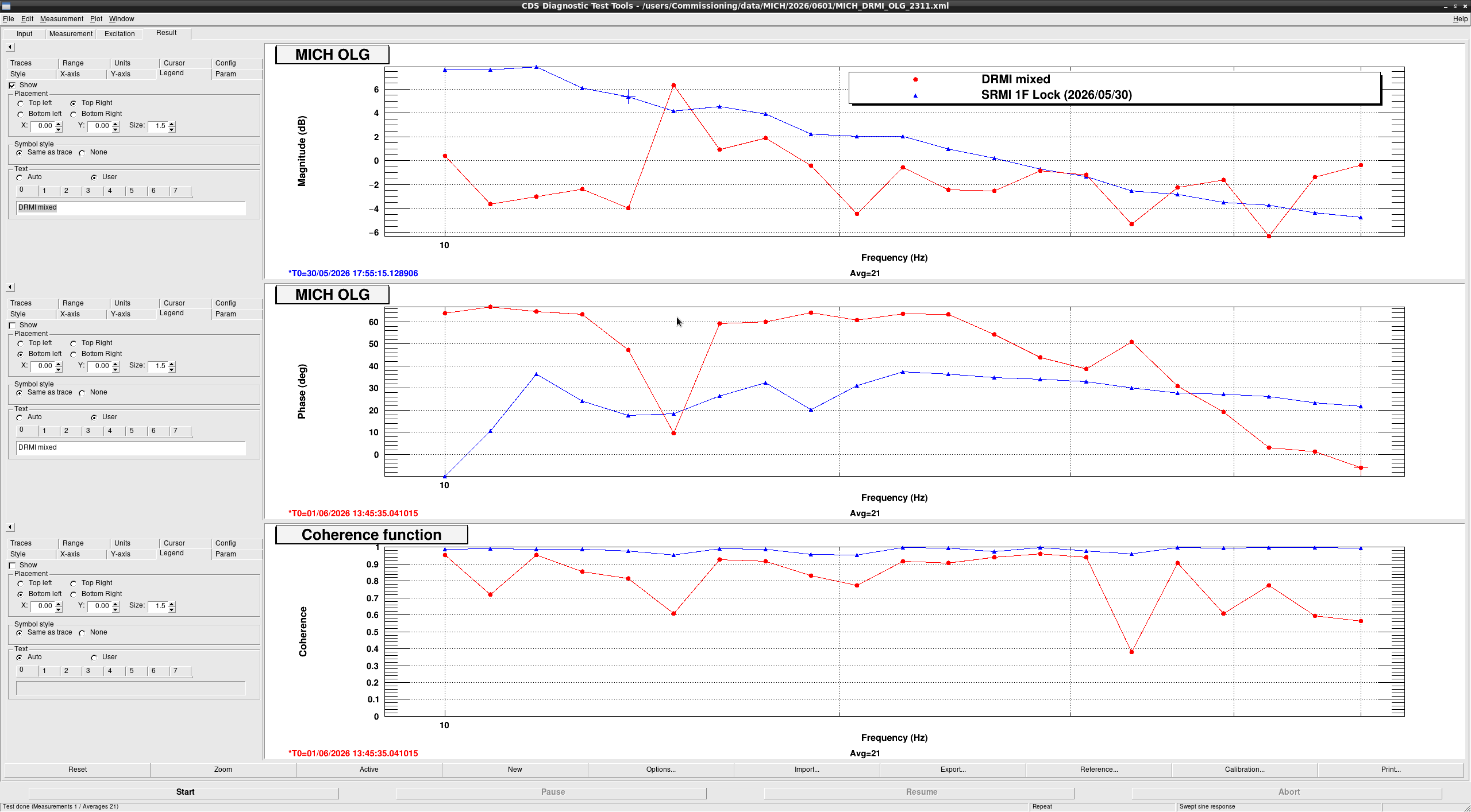
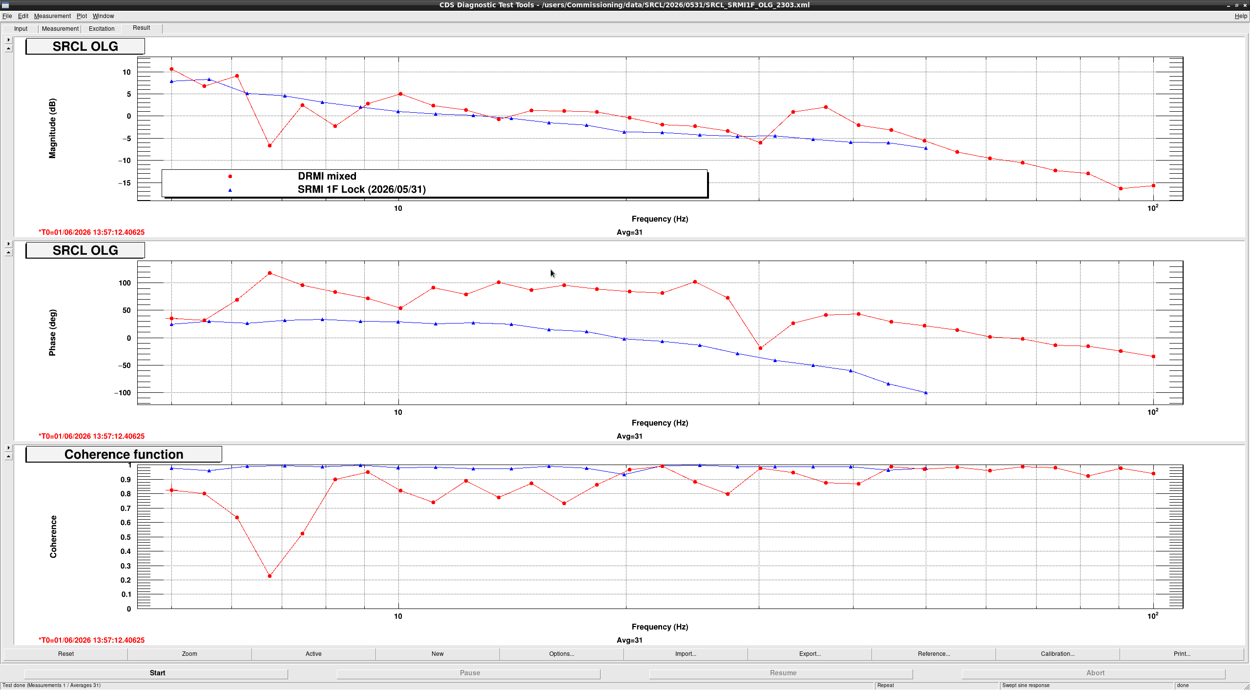
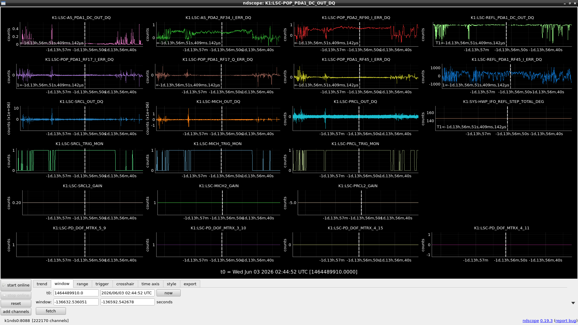
With these conditions, we could lock DRMI in> 5 minutes (Fig. 3). We could barely measure the open-loop transfer function of each DoF, as attached (Fig.4 for PRCL, Fig. 5 for MICH, Fig. 6 for SRCL). Probably because of control instability, the measurement data have lower coherence, so it is not clear exactly what they looked like.
Issues
As reported here, the buildup of AS34 would be more than 5, whereas it is currently 0.5-0.6. It could be that the current locking point is not what we want due to the incorrect signs of the gains and the offset in the error signals. However, the POP90 buildup looked good (it's almost 1, as expected), suggesting the SRCL might be controlled at a weird point. On the other hand, the buildup during DRMI swings reached ~2 and never reached 5. It could be due to poor alignment of SRMI, but I'm not sure.
Another issue is the coupling between the DoFs. The open-loop transfer functions looked very weird in shape, especially in the 10s of Hz, and we suspect the couplings are the cause. At least, we know the demodulation phase of REFL51I is far from optimal (~7 deg rotated from the optimal angle, according to Ushiba-san). We have to tune the phase in SRMI or DRMI, and also tune the control gain again.


