[Abe, Tanaka, Hasegawa, Fujimoto, Saito]
To use in the PLL system, we verified the output signal of a Phase Frequency Discriminator (PFD) built by Nishino-san and brought from Mitaka. A PLL test was performed using Moku:Go and Moku:Lab. In addition, the open-loop transfer function was measured.
- First, the output signal of the PFD was examined. Please refer to JGW-D1809187 for the circuit diagram. A signal generated by the Moku:Go function generator with an amplitude of 300 mVpp and a frequency of 10.1 MHz was input to the PFD as the RF signal, while another signal with an amplitude of 300 mVpp and a frequency of 10 MHz was input as the LO signal. The output signal was then observed using the oscilloscope function of Moku:Lab. The observed waveform resembled a partially saturated version of Figures 8 and 9 in the datasheet of the PFD component AD9901KP. In addition, when the RF signal was changed to 10 MHz and the LO signal to 10.1 MHz, the output signal was found to invert. Furthermore, when the frequency difference between the RF and LO signals was reduced to 1 Hz and the output signal was observed as a function of phase difference, a linear response was confirmed, although part of the signal appeared to be saturated.
- However, since this behavior was considered acceptable for practical use, we proceeded to test whether PLL operation could be achieved using Moku:Go and Moku:Lab. First, a signal with an amplitude of 300 mVpp and a frequency of 10.1 MHz generated by the Moku:Go function generator was input to the PFD as the RF signal, while a signal with an amplitude of 300 mVpp and a frequency of 10 MHz was input as the LO signal. Next, the PFD output signal was connected to Moku:Lab and passed through a flat filter with 0 dB gain implemented using a PID controller. The output signal from Moku:Lab was then fed back to Moku:Go, where the frequency modulation function of the function generator was used to apply feedback. While observing the RF and LO signals on the oscilloscope, it was found that, after the control loop was engaged, the RF signal stopped drifting relative to the LO signal (Photo 1). The yellow trace corresponds to the RF signal, and the blue trace corresponds to the LO signal. Therefore, the PLL appeared to operate successfully.
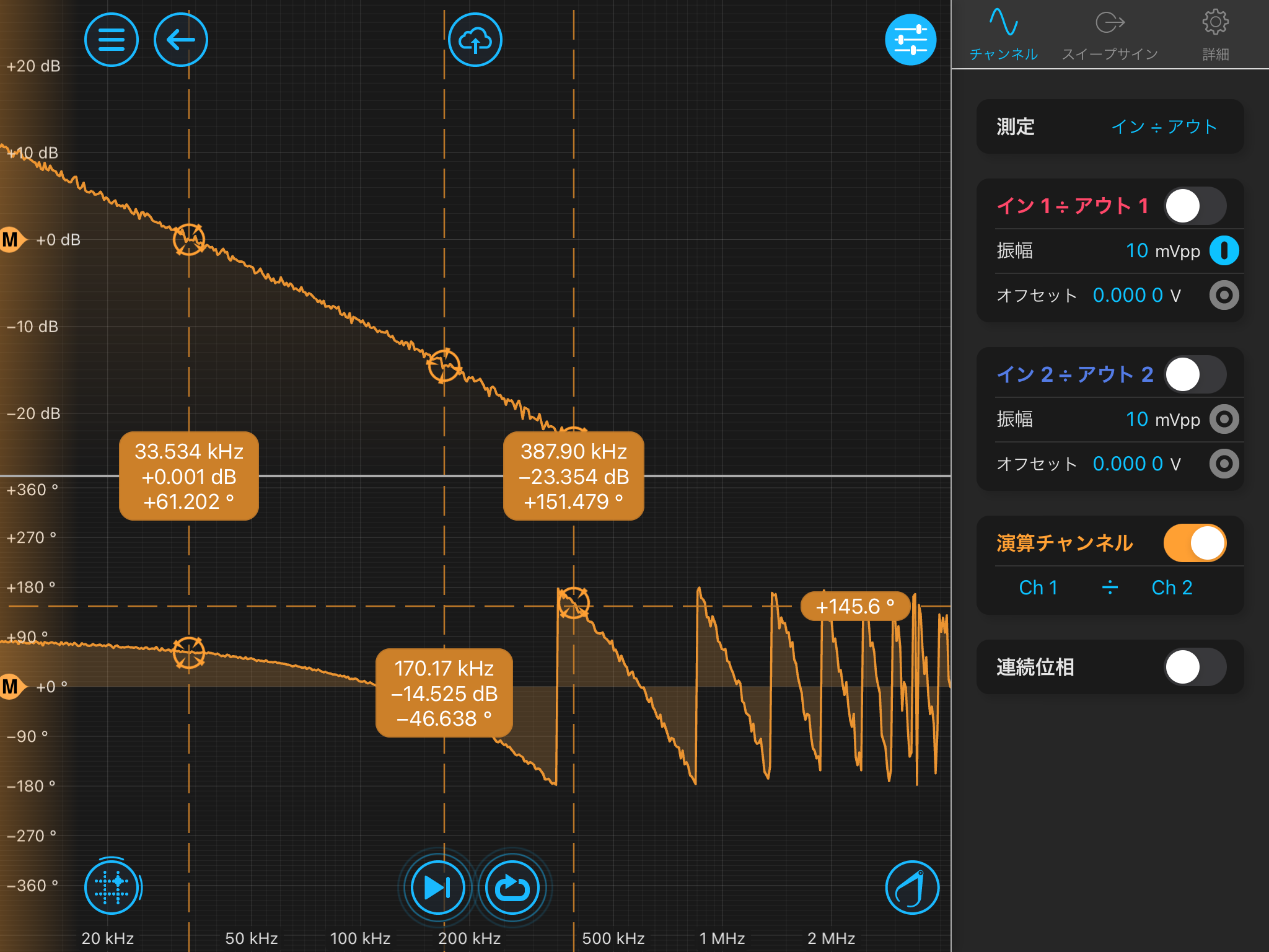
- Next, the open-loop transfer function was measured. Another Moku:Lab unit was prepared, and the measurement was performed using the input and output signals of the Moku:Lab used for filter generation. The excitation signal was applied through the other input port and summed using the PID controller. The signal path connected to PID Controller Output 1 was used for the PLL loop, while the path connected to Output 2 was used for open-loop transfer function measurements. As a result, the UGF was found to be around 387.90 kHz, as shown in Photo 2. Since the phase had already crossed 180 degrees, the loop should theoretically have been unstable. However, the oscilloscope still indicated successful PLL operation, suggesting that the open-loop transfer function might not have been measured correctly.
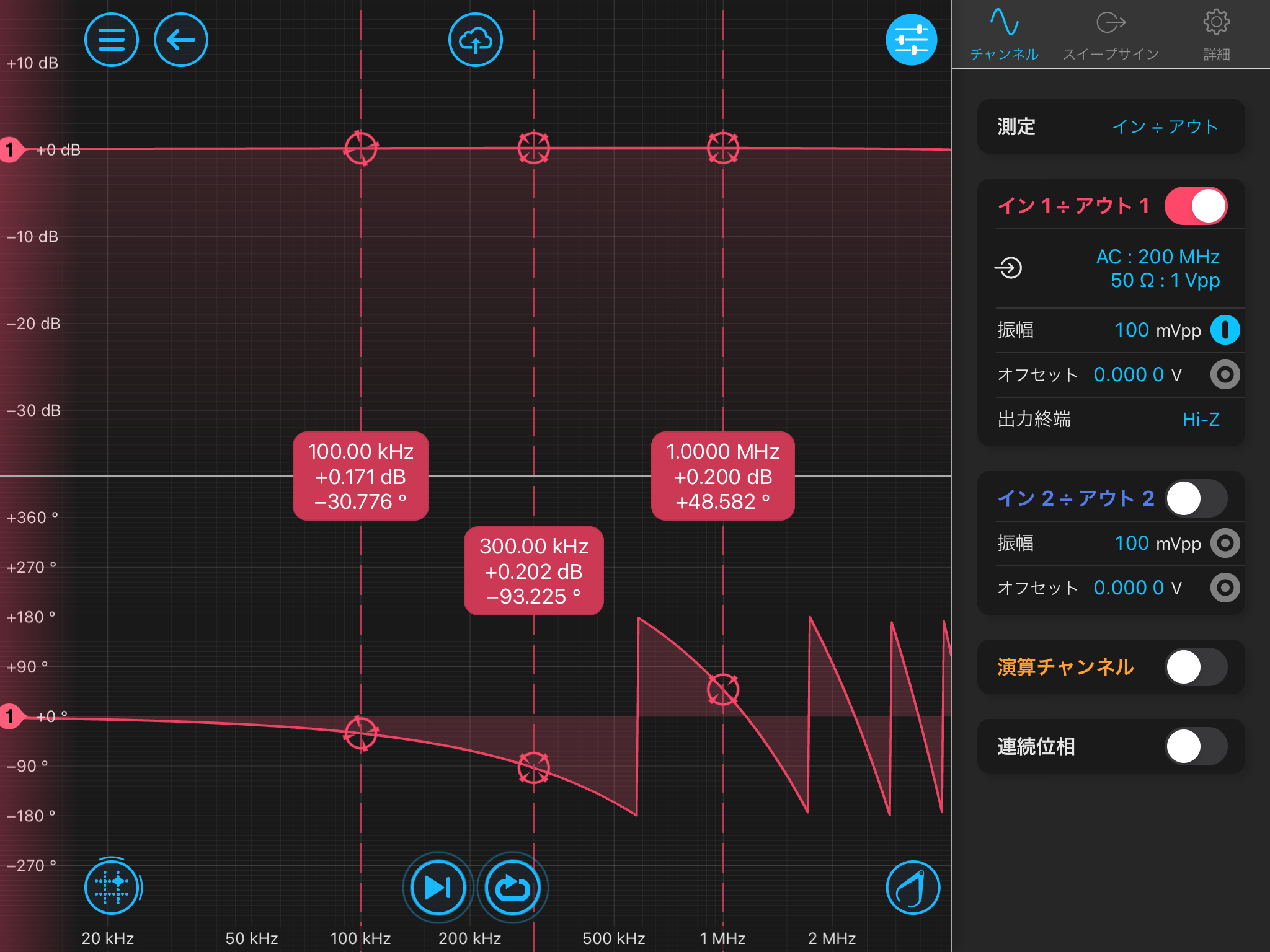
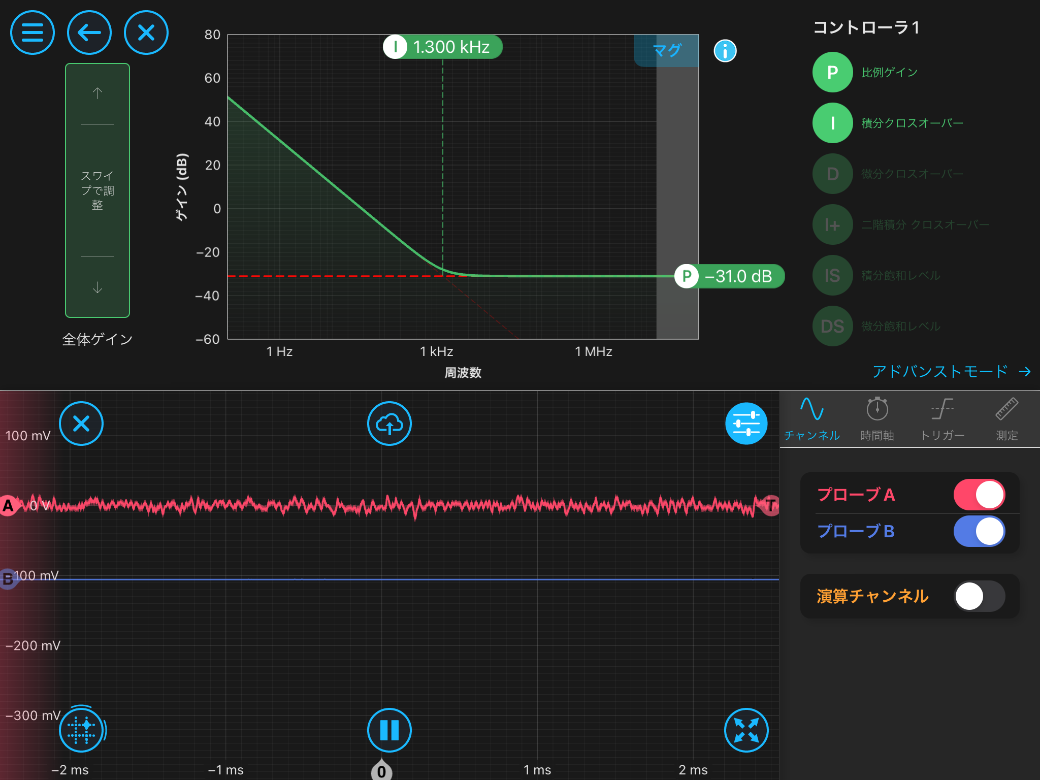
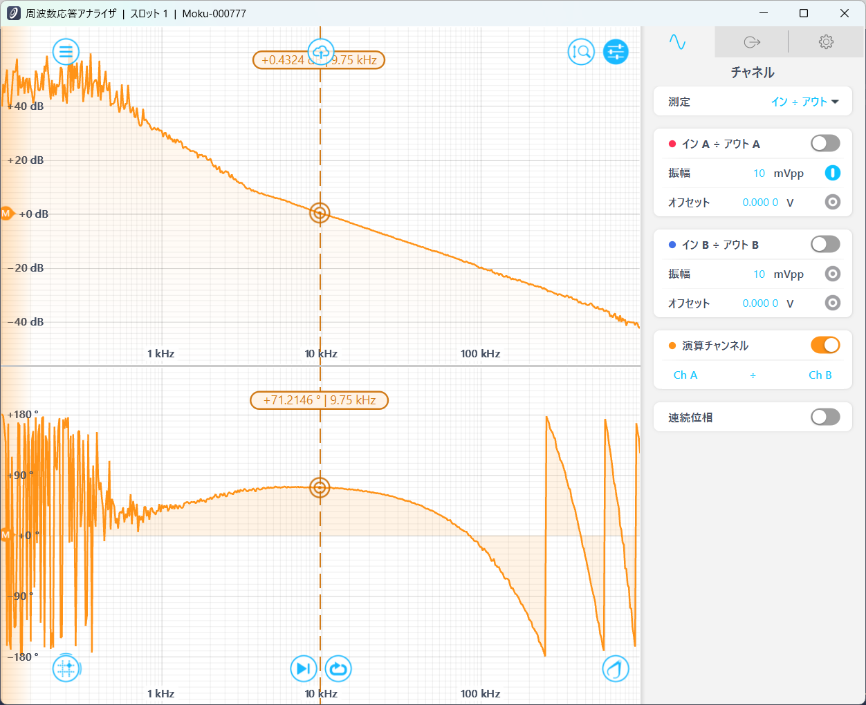
- Upon closer consideration, because a filter existed between the signals used for the measurement, the measured transfer function actually represented only the Moku:Go and PFD section. In other words, if the open-loop transfer function is represented as G and the filter transfer function as F, the measured quantity was -G/F. To determine the phase delay of the filter section, the transfer function of Moku:Lab was measured separately (Photo 3). From this measurement, the phase delay of Moku:Lab was estimated to be approximately 0.865 μs. Based on this result, the gain of the PLL loop filter alone was changed to -23 dB so that the UGF would shift to a frequency region where the Moku:Lab phase delay is nearly zero. The resulting transfer function is shown in Photo 2. Since the oscilloscope signal also behaved similarly to that shown in Photo 1, the PLL operation is considered to have been successful.