Reports 1-1 of 1 Clear search Modify search
VIS (SRM)
ryutaro.takahashi - 22:19 Tuesday 07 April 2026 (36711) Print this report
Adjustment of suspension

[Washimi, Takahashi]

We adjusted the suspension.

  • After offloading the BF and F1 GAS filters, we adjusted the V1/2/3 OSEM positions to the center of the range.
  • We removed the 1kg ballast ring from the IP. The resonant frequencies for L and T were changed (klog).
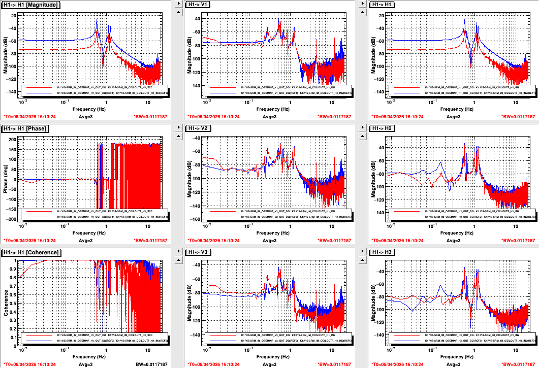
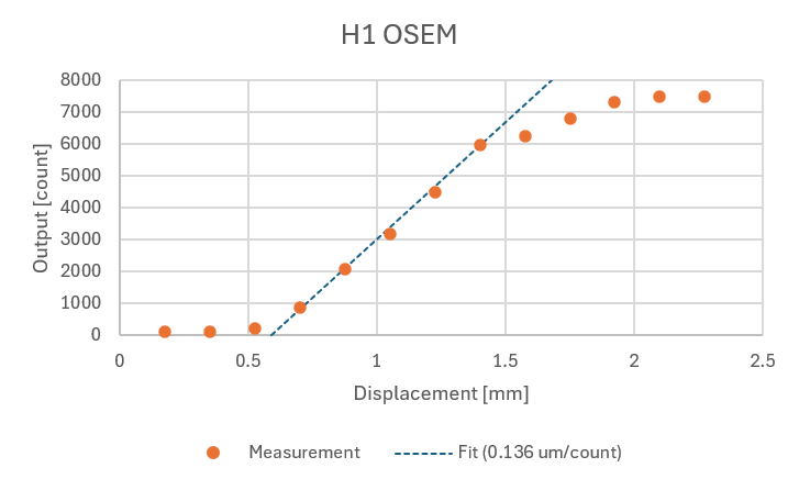
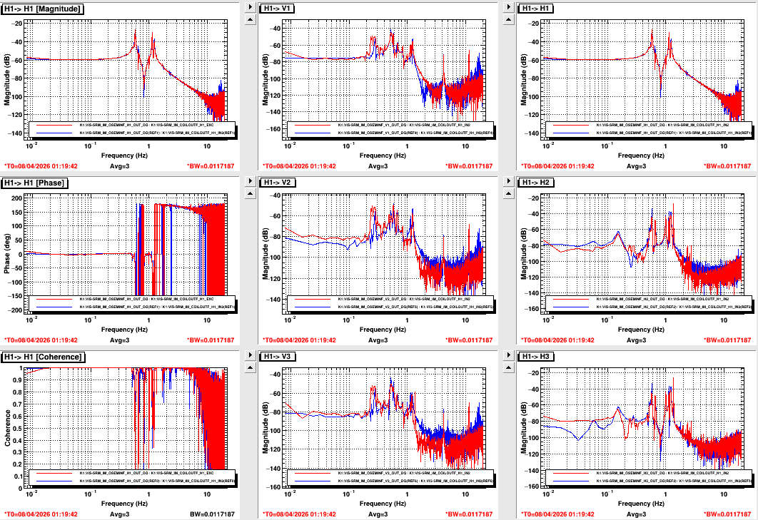
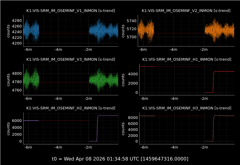
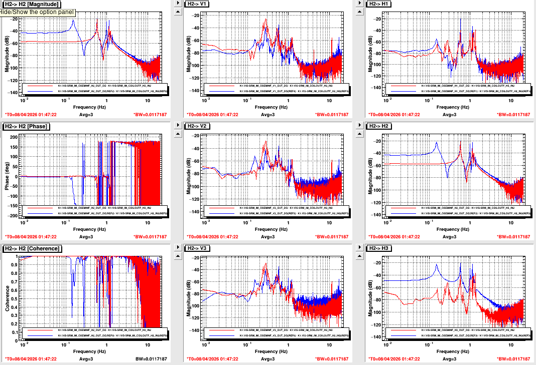
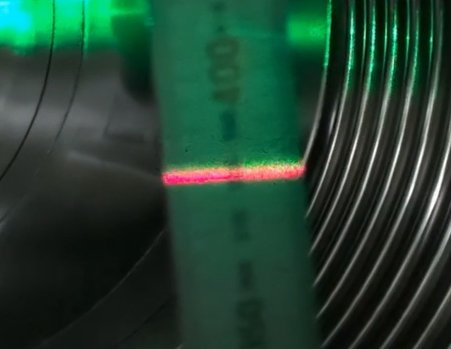
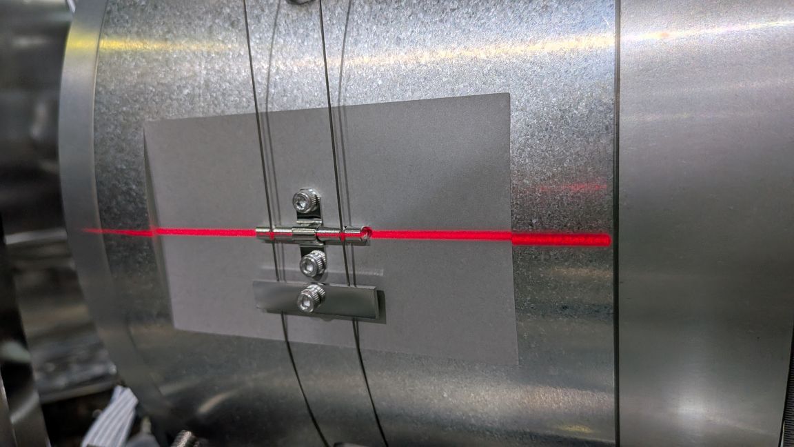
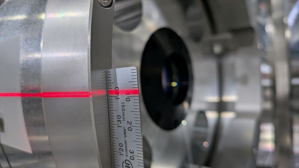
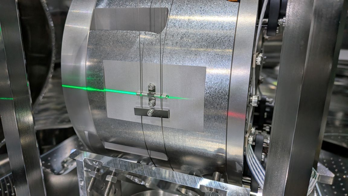
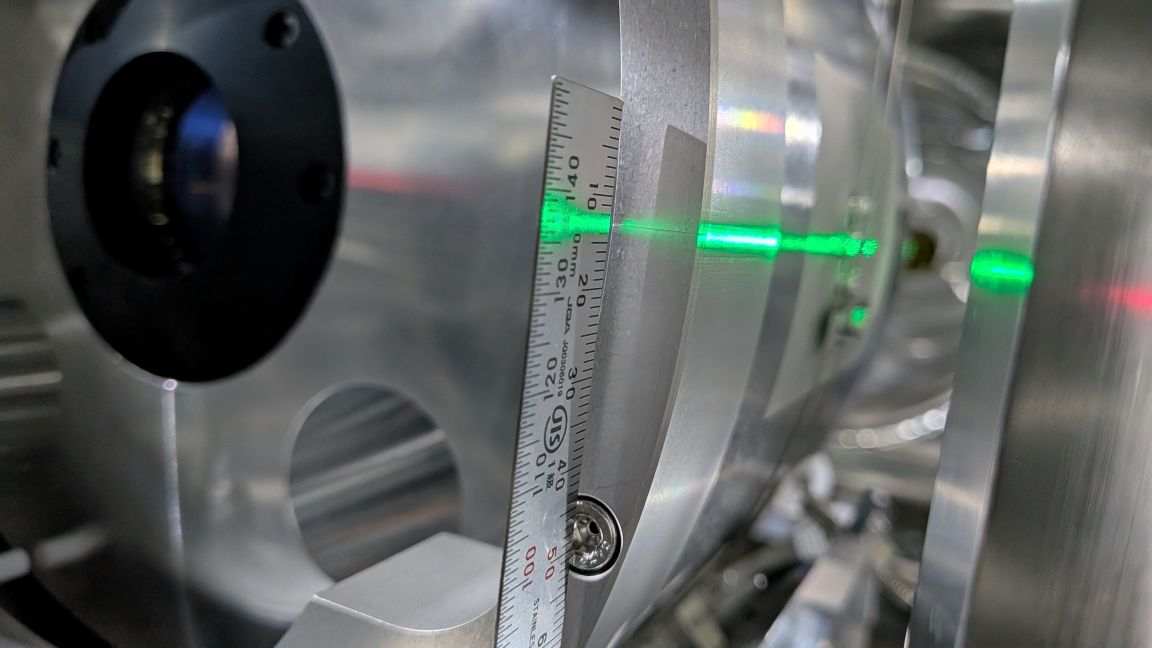
  • We investigated the small gain of the H1 OSEM in the IM transfer functions (Pic. 1). We checked the forward voltage of the diodes and resistance at the feedthrough flange (Table). They were normal. We calibrated the OSEM output by moving the IM body in the 1/4 pitch of the M4 screw for the EQ stop (Pic. 2). The maximum value was 7500 counts (Pic. 3). The calibrated coefficient was 0.136 um/count (Pic. 4). The original coefficient was 0.299 um/count.
Pin# H1 cf. H3
1-6 0.531V 0.531V
2-7 19.1Ω 19.0Ω
3-8 1.073V 1.072V


Images attached to this report
Comments to this report:
ryutaro.takahashi - 11:48 Wednesday 08 April 2026 (36718) Print this report

[Washimi, Takahashi]

We investigated the IM H1 OSEM. The transfer function was recovered when the OSEM position was in the linear range, 5600 (Pic. 1). We swapped the stellite box channel for H1 and H2. The output was changed (Pic. 2) as shown in the table. Ch. 1 output was smaller than that of Ch. 2 in both cases. The satellite box has a problem. The transfer function of H1 using Ch. 2 showed a gain higher than the reference (Pic. 3).

  Before After
Ch. 1 5600 (H1) 4500 (H2)
Ch. 2 6000 (H2) 7500 (H1)


Images attached to this comment
ryutaro.takahashi - 18:04 Wednesday 08 April 2026 (36723) Print this report

[Washimi, Takahashi]

  • We removed the 1kg ballast ring from the IP. The resonant frequencies for L and T were close to the reference (klog).
  • We investigated the IM H1 OSEM. Details are here.
  • We adjusted the H1 OSEM position to 2800 (near the middle of the dynamic range). The H1 OFFSET in "K1 SRM IM OSEMINF FILTERS" was changed from -6315.5 to -3700.
  • We checked the height of the TM/RM. One laser leveler (red) was set to the height reference on the chamber (Pic. 1). The other laser leveler (green) was set to the red line (Pic. 2). The red line consisted of the X+ side wire breaker on the RM (Pic. 3), and was 0.5mm higher than the marker on the front ring of the RM (Pic. 4). The green line also consisted of the X- side wire breaker on the RM (Pic. 5), and consisted of the marker on the front ring of the RM (Pic. 6).
  • We adjusted the gap of the EQ stops and took pictures of them.
Images attached to this comment
Search Help
×

Warning

×