Reports 1-1 of 1 Clear search Modify search
VIS (SRM)
takafumi.ushiba - 12:53 Wednesday 01 April 2026 (36681) Print this report
Investigation on FLDACC

Summary:

Not only H1 but also H3 FLDACC does't seem healthy.
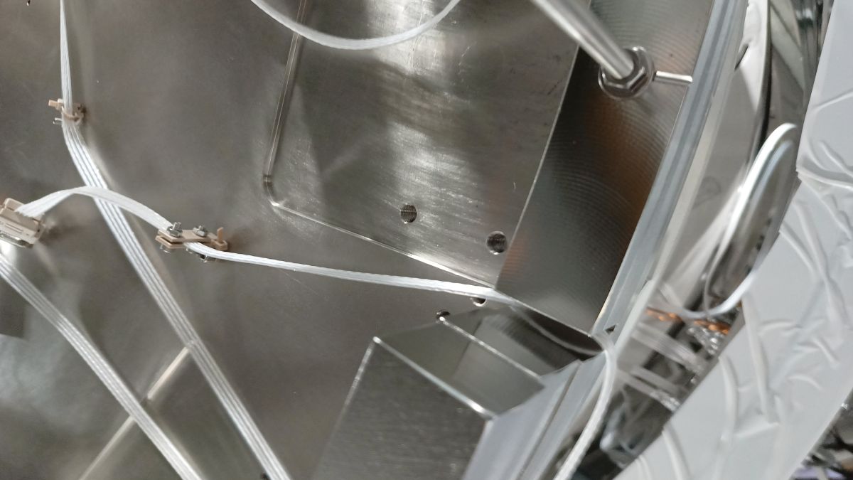
It is very suspicious that they are rubbing somewhere.

What I did:

To investigate if the pendulum itself is healthy or not, I performed the DC response ceck for FLDACCs.
Procedure is as folows:

1. Engage FLDACC feedback controls so that pendulum is aligned with respect to the LVDT.
2. Turn off INPUT of FLDACCSERVO filter banks to hold the outputs.
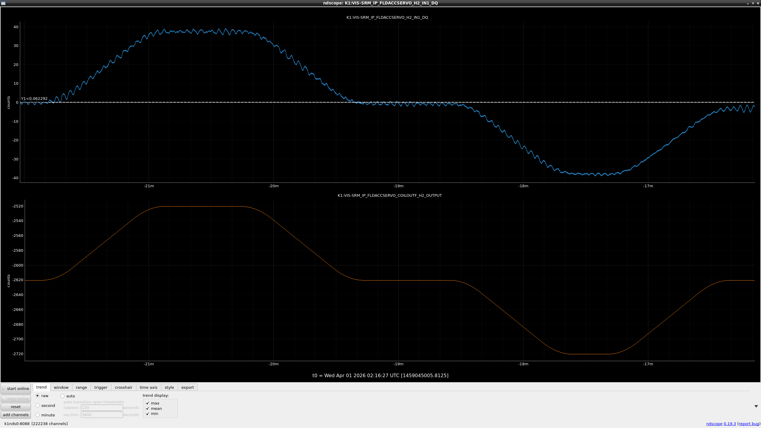
3. Change offsets as +100, 0, -100, and 0 with the ramp time of 60 seconds.

Figure 1, 2 and 3 show the result of H1, H2, and H3 FLDACC signals, respectively.
H1 FLDACC signals moves smoothly in the positive direction while not in negative direction.
H2 FLDACC signals moves smoothly in both directions.
H3 FLDACC signals moves smoothly in the positive direction while not in negative direction as well as H1.
So, only FLDACC H1 seems healthy.

Since there is large hysteresis in H1 and H3 FLDACCs, it is suspicious that these proof masses are rubbing somewhere.

Images attached to this report
Comments to this report:
ryutaro.takahashi - 22:58 Thursday 02 April 2026 (36693) Print this report

[Ushiba, Washimi, Takahashi]

We went to investigate the H1 and H3 FLDACCs. We opened the actuator housing and checked the movable range with the LVDT. It was from +80 (actuator side) to +1700 (LVDT side) in H1 and from -2500 to 750 in H3. When we removed the actuator yoke (Pic. 1), the range of the actuator side extended to -600 in H1 (Pic. 2). The actuator coil (Pic. 3) may be touching the yoke. We inserted the 0.5mm shim between the coil bobbin and the folded pendulum body in H1. The range did not change in H3. The folded pendulum has gone to an unstable mode in both H1 and H2. We removed the counterweight of  25g for H1 and 19g for H3. The transfer functions of these two folded pendulums were almost consistent and showed the same resonant frequency of 0.3Hz (Pic. 4). Before closing the top chamber, the Lemo cable for the actuator had broken in H3. Pic. 5 shows the displacement spectra of the H1 and H2 FLDACCs. The sensitivity of the H1 FLDACC was improved.

Images attached to this comment
ryutaro.takahashi - 18:59 Friday 03 April 2026 (36696) Print this report

[Washimi, Takahashi]

We repaired the broken Lemo cable for the H3 FLDACC. Though the cable was connected to the H3 FLDACC again, there was still no signal. We checked the in-vacuum PTFE cable too. The connections of some pins (#1, #6, #7) were unstable or failed. We repaired the PTFE cable. We could confirm the signal and the actuation in the H3 FLDACC. After that, we adjusted the tilt of the all FLDACCs so that the LVDT signals can fluctuate around zero.

Additionally, we fixed the PTFE cable for the H2 FLDACC with a peek tie (Pic.) and removed the 1kg ballast ring from the IP.

Images attached to this comment
Search Help
×

Warning

×