[Takahashi, Hirata, Washimi]
We installed the FLDACCs in the pre-isolator.
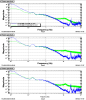
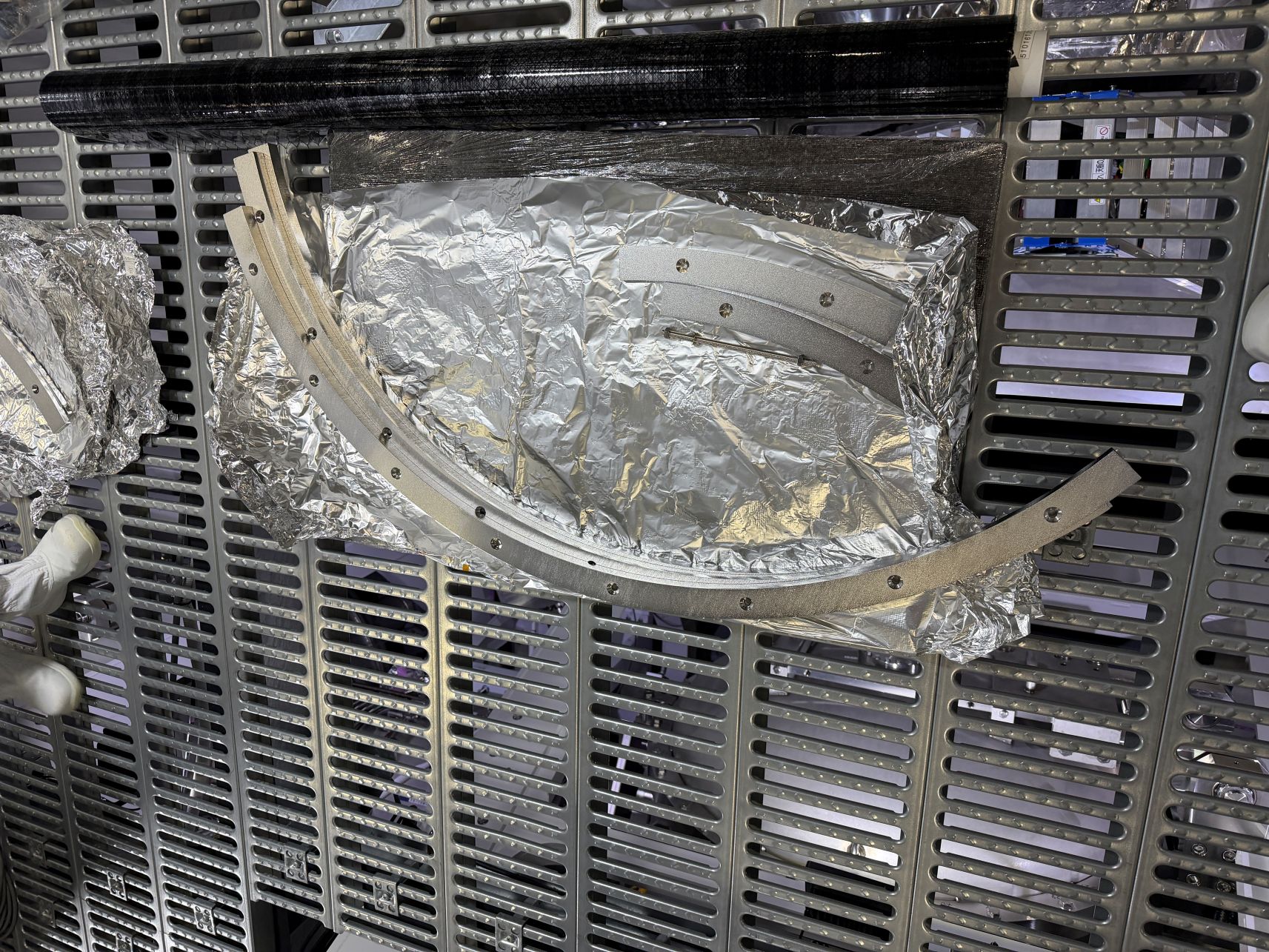
- Set the attachment plates on the top table. Location is shown in Picture 1.
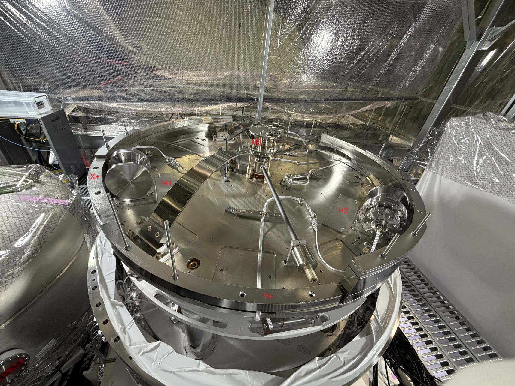
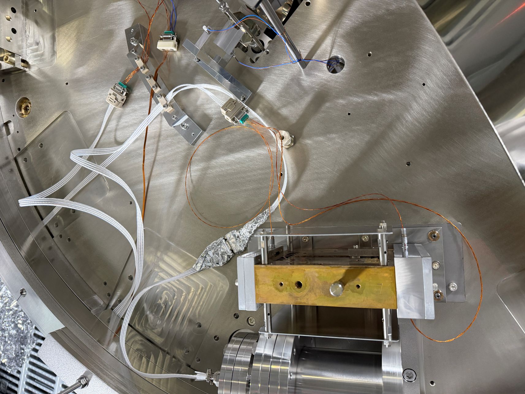
- Moved the assembled FLDACC units to the upper floor one by one (Picture 2), and removed the lower stopper, then put the unit on the attachment plate.
- Attached the counterweights to the proof mass along with the tuning results. Removed the protection covers temporarily during this work.
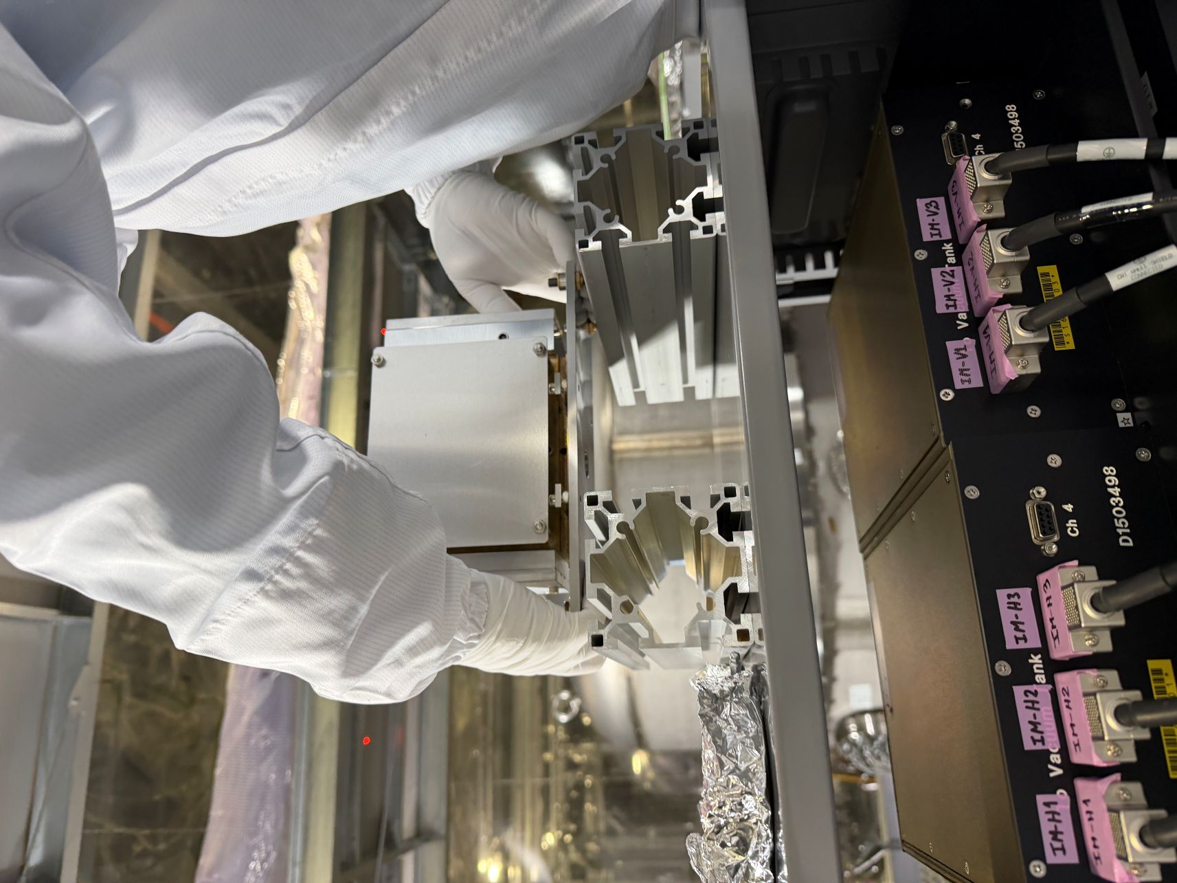
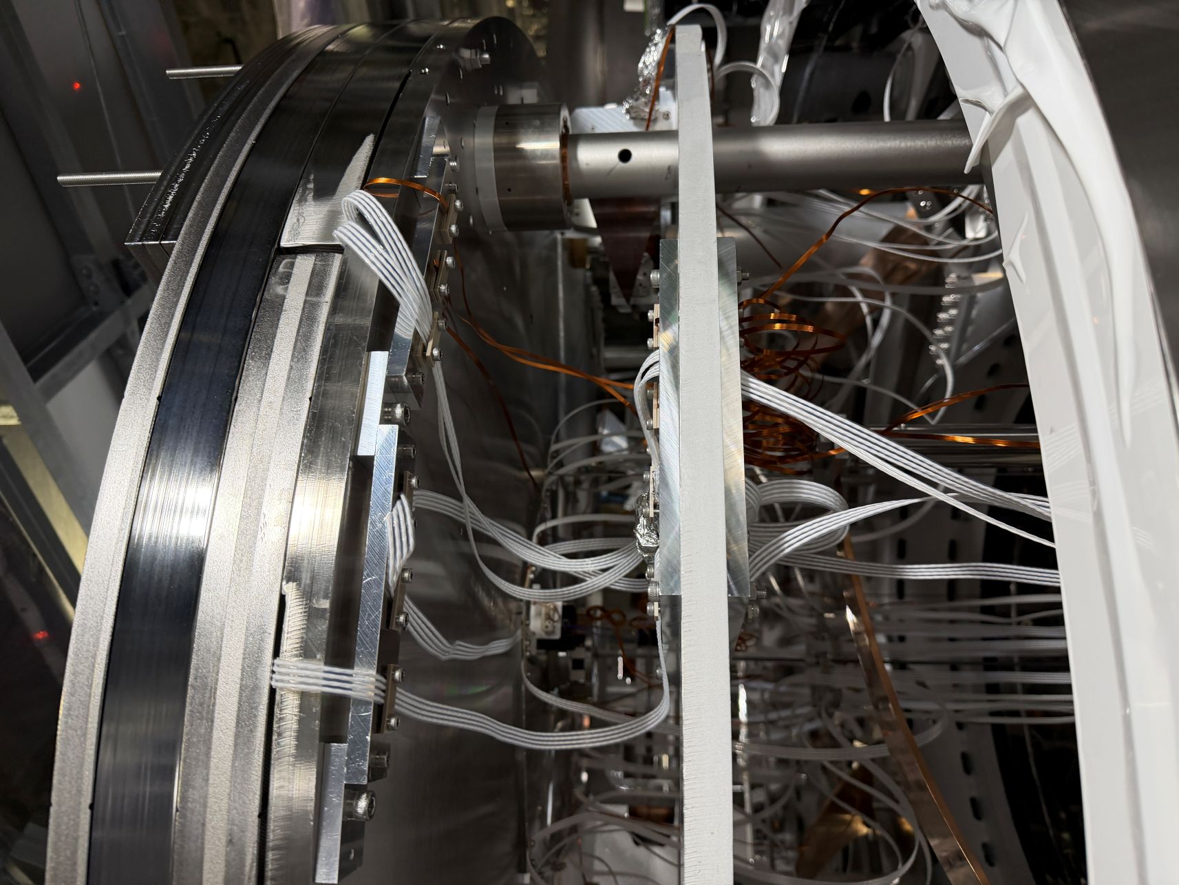
- Adjusted the tilt of the units (Picture 3).
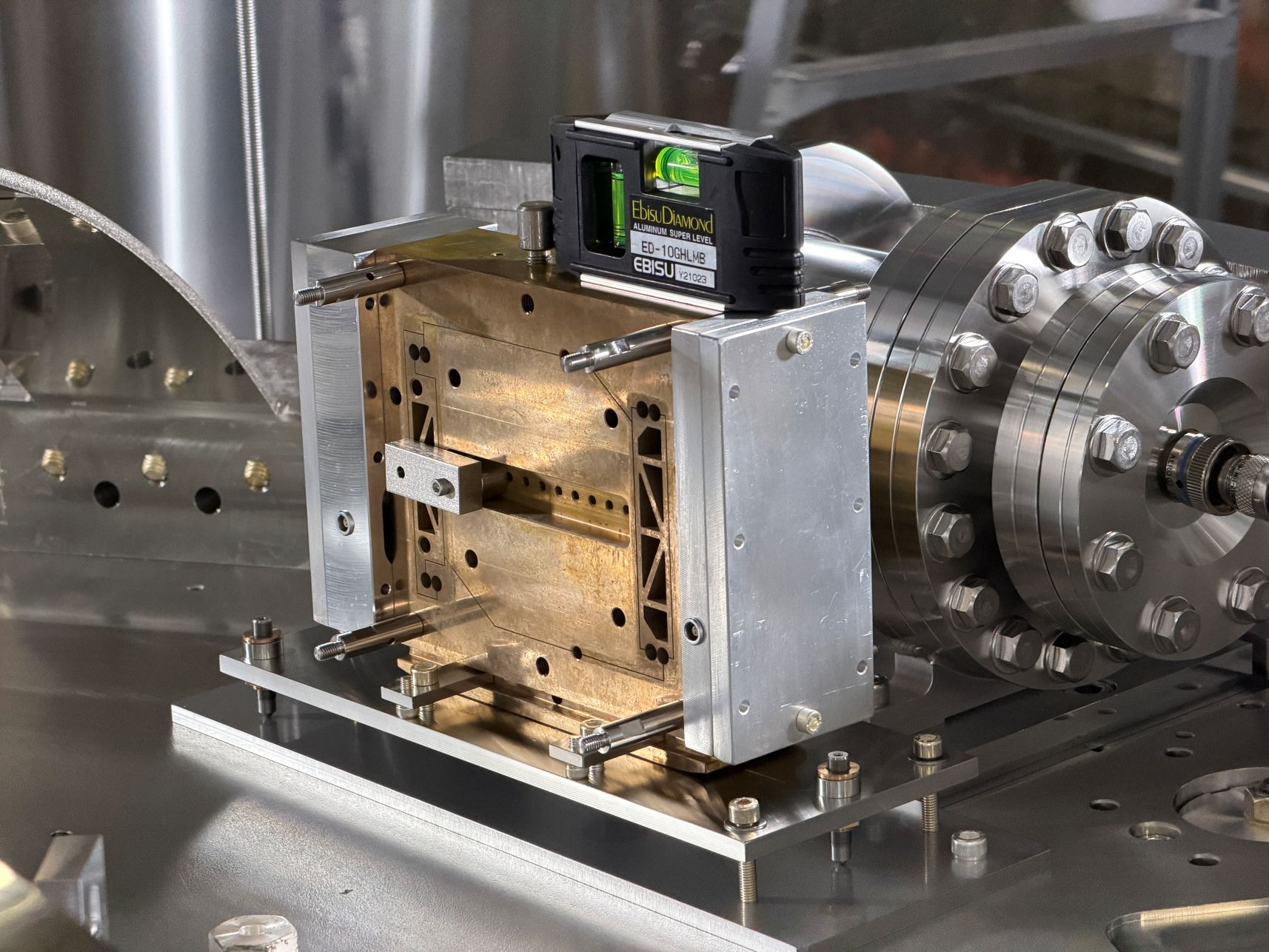
- Removed three ballast rings of 8.3kg (Picture 4) and added one small ballast ring of 1.0kg to compensate for the additional weight of three units of 8.0kg.
- Installed the in-vacuum cables (Pictures 5 and 6). The Kapton cables from the units were connected to the PTFE cables from the feedthrough flange on the table.
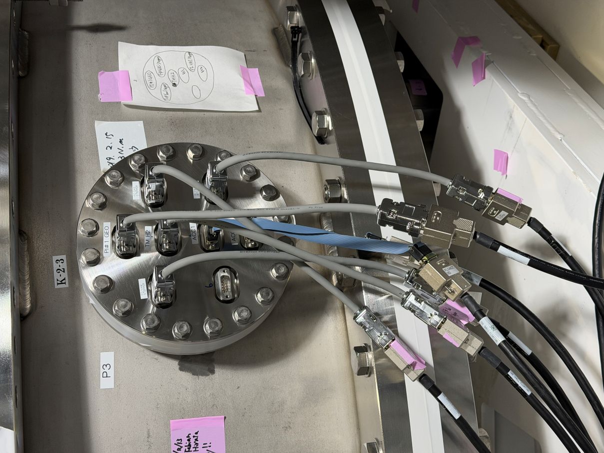
- Connected the outer cables to the feedthrough flange with the flip cables (Picture 7). New flip cables were out of stock, so we used the old type cables.
- Checked the resistance of the coils in the FLDACC at the feedthrough flanges. Initially, the H3 1-6pin was disconnected due to a loose contact at the relay point.
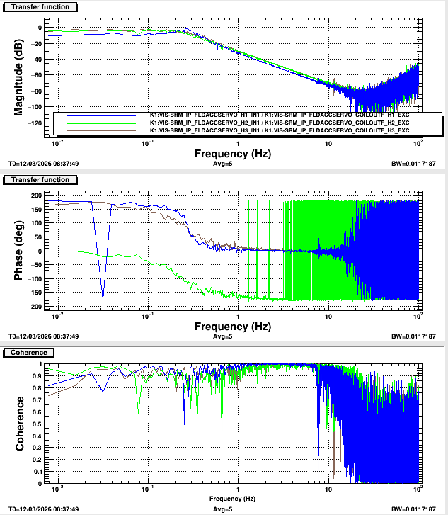
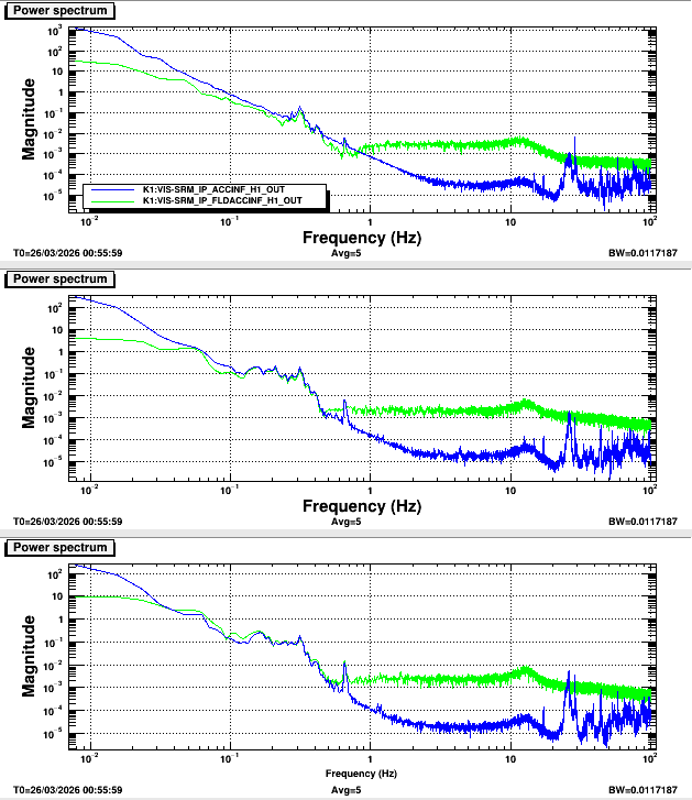
H1 [Ω] H2 [Ω] H3[Ω] 1-6 47.3 47.2 53.0 2-7 55.2 55.2 62.5 3-8 5.5 5.1 4.9 - Checked the signals on the daiaggui. Measured the transfer functions (Picture 8).


