Reports 1-1 of 1 Clear search Modify search
MIF (ASC)
kentaro.komori - 3:38 Thursday 29 January 2026 (36241) Print this report
First trial of high-bandwidth ASC: DHARD pitch

[Tanaka, Dan, Sugioka, Komori]

Abstract:

We have started a trial to increase the ASC bandwidth in order to reduce power fluctuations inside the arm cavities, which can mitigate non-stationary and non-linear noises in the interferometer.
The first target is the DHARD pitch loop, for which we aim to increase the unity gain frequency (UGF) up to a few hertz, although this has not been succeeded yet.

Details:

We have been observing non-stationary noise and likely non-linear noise around 100 Hz in KAGRA, which must be addressed to achieve better sensitivity.
One possible cause is the large fluctuation of the arm transmission power, exceeding 1%, whereas it is typically 0.01–0.1% in LIGO.
In addition, the ASC bandwidth of the arm cavities in LIGO is 4–5 Hz, while that in KAGRA is only around 0.5 Hz.
Since the ASC control noise coupled into DARM is much smaller than the current sensitivity, we can increase the ASC bandwidth to significantly reduce the transmission power fluctuations.

The first target is DHARD pitch.
The pitch resonant frequencies of the MN, IM, and TM are 0.8 Hz, 45 Hz, and 7.5 Hz, respectively.
Therefore, within an ASC bandwidth of a few hertz, these three masses can be regarded as a single effective pendulum, making it relatively straightforward to increase the UGF.

As a first step, we designed a new filter for higher-bandwidth operation using a simple phase compensation filter.
Another important concept of the new ASC scheme is that the feedback is applied only to the MN, and not to the TM, in order to avoid noise contamination.
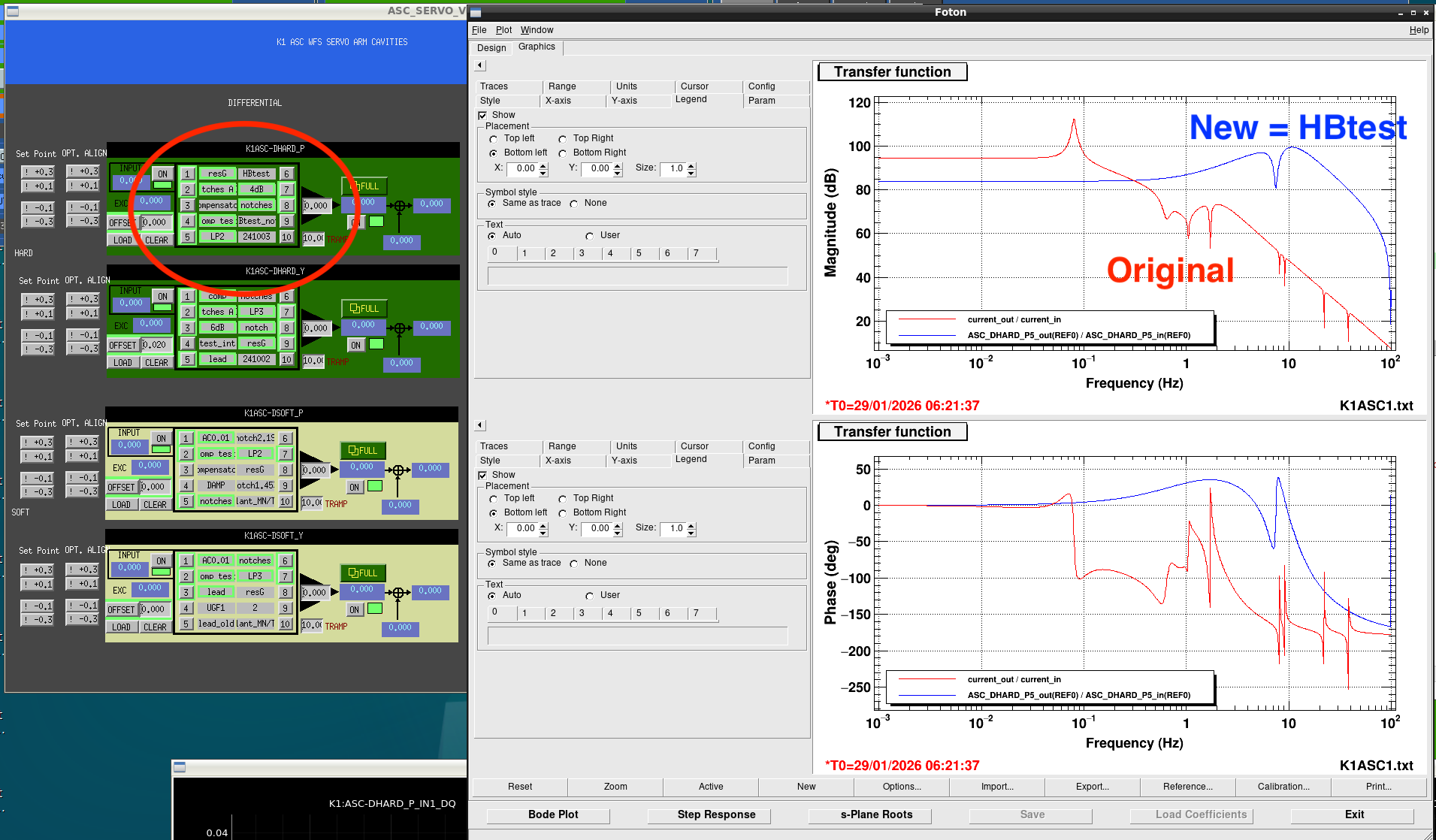
The expected openloop transfer functions are plotted in Fig. 1, where the blue and red curves correspond to the current and targeted designs, respectively.
Although the loop has not yet been fully optimized, the new design achieves a UGF of approximately 2 Hz.

We implemented this new filter through the following steps:

  • Reducing the {D, C}{HARD, SOFT} gains from −1 to 0.3 to decrease the ASC UGF from 0.3–0.5 Hz to around 0.1 Hz, ensuring that the UGF is below the crossover frequency between the MN and TM (0.1 Hz).

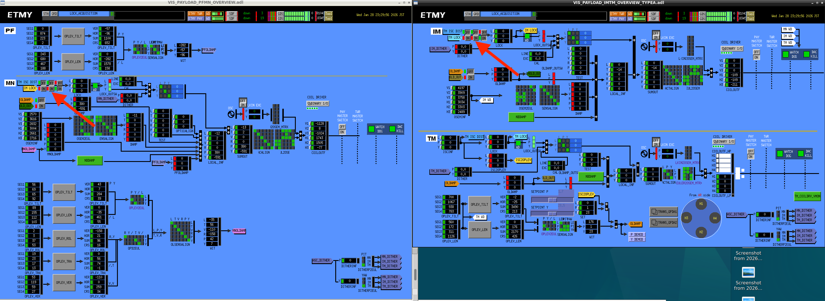
  • Turning off the TM LOCK filter and configuring the ASC to actuate only on the MN.

  • Turning off the DHARD pitch control, replacing the old filter with the newly designed one, and re-enabling the control.

We successfully closed the DHARD pitch loop with the new filter and measured the openloop transfer function, shown by the red dots in Fig. 2, which can be compared with the conventional loop shown by the blue dots.
However, the achieved UGF is still low, and an oscillation at 0.8 Hz appeared when we increased the gain further.

We will investigate the origin of this instability in more detail.
In addition, the coupling between DHARD and CHARD appears to be significant, so improving the decoupling between these degrees of freedom is another important task.

Images attached to this report
Comments to this report:
dan.chen - 17:24 Thursday 29 January 2026 (36246) Print this report

[Tanaka, Komori, Sugioka, Dan]

Background (Issue found in the previous day’s work)

During the ASC high-band work on the previous day, Komori-san found a critical issue: the suspension MN LOCK P filter bank (FB) contains an integrator. Because of this, the phase is already significantly rotated around ~1 Hz. When TM LOCK P is turned off, the MN side cannot properly take over the control above ~0.1 Hz, resulting in an unstable configuration.

In the origianl configuration,

  • above ~0.1 Hz the MN contribution is small,
  • and the TM loops mainly maintain the control in that band.

In the current attempt to realize a high-band configuration where MN also controls above ~0.1 Hz, the MN LOCK filtering needed to be modified.


Plan for today

  • In the suspension MN LOCK P filter bank (FB), introduce a new high-band filter FM4 = HBtest to replace (fig 001):
    • FM9 = int
    • FM10 = LP1
  • Combine it with the newly prepared K1ASC-DHARD_P filter (FM6) to test whether the system can be locked with the signal and only with MN stage. (fig 002)
  • We do not hand the control back to the TM loops. Instead, we adjust the DHARD-side gain while measuring OLTF to confirm stability and related behavior.

Preparation

  • Disable TM act path for all four TMs: set TM LOCK P gain from 1 to 0.
  • For three Type-A suspensions (all except ETMX), switch K1:VIS-{}_HIERSWITCH_P to OFF so that signals can reach the MN without going through the TM path. (ETMX was already OFF.) (fig 005)
  • In MN LOCK P filter bank:
    • turn OFF FM9 and FM10,
    • turn ON FM4 = HBtest (fig 001).
    • This filter is designed so that the magnitude becomes flat around ~1 Hz, and the phase is advanced in that region.

Temporary modifications to ASC_LOCK GRD (fig 003)

For this test, we temporarily modified parts of the ASC_LOCK GRD.

  • For the Type-A suspension MN LOCK filter switching:
    • Original: turn ON FM9
    • Test setting: turn ON FM4 = HBtest
  • We also adjusted the behavior around INCREASE_SOFTHARD_GAIN so that:
    • SOFTs are closed with gain staying at -1,
    • HARDs stop at gain -0.2,
    since we want to manually increase DHARD-side gain during the OLTF measurements.

Procedure

  1. Request ENGAGE_WFSDC on LCK_LOCK. (This also auto-requests ASC_LOCK to ENGAGE_WFSDC.)
  2. Request INCREASE_HARDSOFT_GAIN on ASC_LOCK:
    • SOFT sides stay at gain -1
    • HARD sides stop at gain -0.2
  3. Set DHARD P gain to 0 to open the loop once.
  4. Switch DHARD P filter bank from the original set (FM1 × FM2 × FM4 × FM5 × FM7 × FM8) to the new filter FM6.
  5. Increase DHARD P gain step-by-step: -0.5 → -1 → -2.
  6. Measure OLTF at each gain state.

Results (fig 004)

  • By increasing DHARD P gain to -1 and -2, we were able to push the UGF to around ~1.5 Hz.
  • Measurement file: /users/Commissioning/data/ASC/2026/0129/DHARD_P_new_filter_OLTF.xml

Findings

  1. If K1:VIS-{}_HIERSWITCH_P remains ON, turning off TM LOCK P stops signals from reaching MN, so MN-dominant control cannot work as intended. We switched it OFF for all Type-A suspensions except ETMX (which was already OFF).
  2. Since this test targeted only the P path, the MN LOCK filters must be configured as:
    • P: FM4 (HBtest)
    • Y: FM9 (usual)
    We updated ASC_LOCK.py accordingly.

Remaining issues

  • Gain peaking is large.
  • We expected stronger low-frequency suppression due to the integrator inside MN LOCK P FM4, but it was not as large as expected.
  • This may indicate insufficient DoF separation and/or residual coupling? Further investigation will be necessary.
Images attached to this comment
kenta.tanaka - 21:06 Thursday 29 January 2026 (36247) Print this report

Michimura, Tanaka

Fig.1 shows the spectra and culmutive RMSs, red is the error signal with new filter when gain = -2, and blue is the one with the old filter.

Thanks to enhance the control bandwidth from 0.3 Hz to ~1.5 Hz, RMS from 100 Hz to 0.2 Hz become approximately 1/3 lower even though there is gain peaking around 2 Hz.

On the other hand, the noise floor above 10 Hz  seems to become larger due to the 1-10 Hz lead filter implemetation. It is necessary to implement the roll off filter. 


Images attached to this comment
kenta.tanaka - 23:01 Thursday 29 January 2026 (36248) Print this report

I restored the script of ASC_LOCK. IFO will be left OBSERVATIO _WITHOUT _LINES. 

Search Help
×

Warning

×