Summary
By applying a large negative offset in MN Pitch, the MN Yaw TF became much better. However, the cross couplings are still very large. Also, the TM OpLev is completely out of range in this state. So, even if we can release the IX suspension, we cannot recover the IFO alignment. Time for warm up?
Pitch adjustment
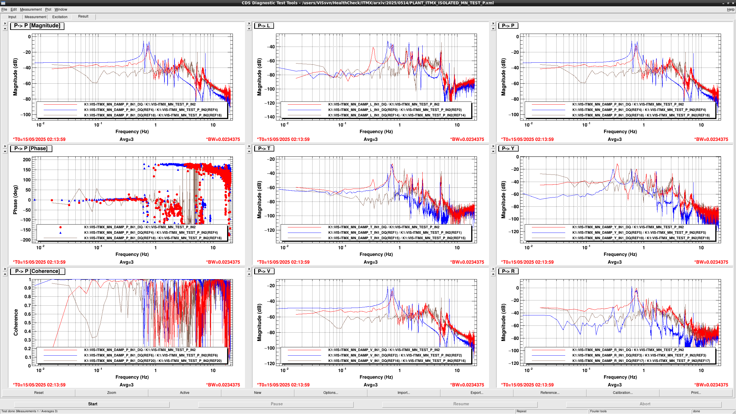
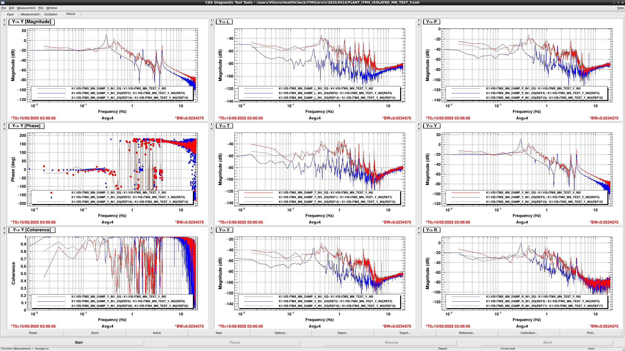
I tried to measure the MN OpLev TFs with a large offset applied to variou DoFs.
In most cases, the TFs were pretty bad. However, when -10000cnts (equivalent to 30000cnts at the coil output) was applied to Pitch, the TF became much better.
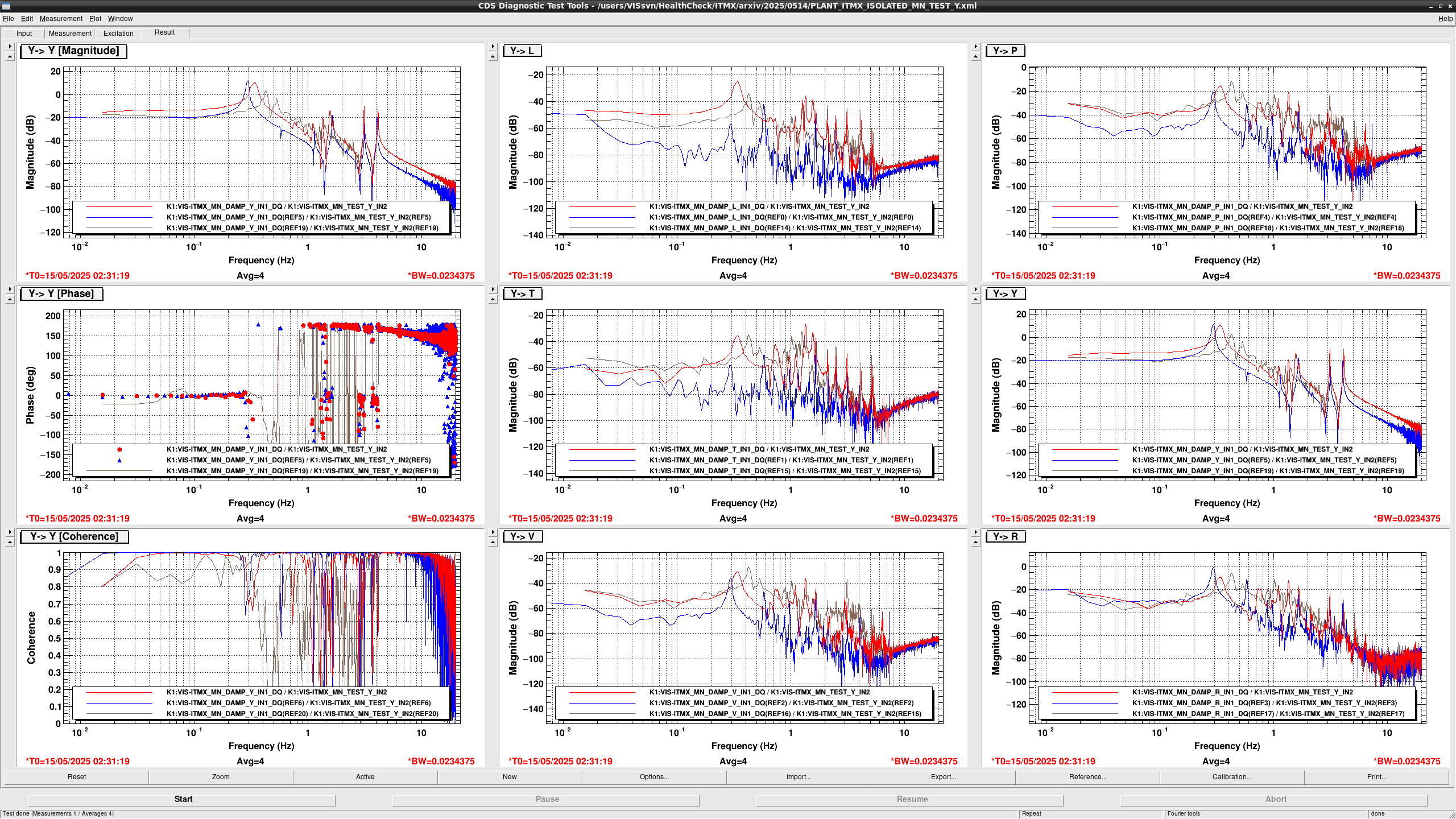
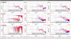
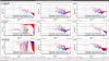
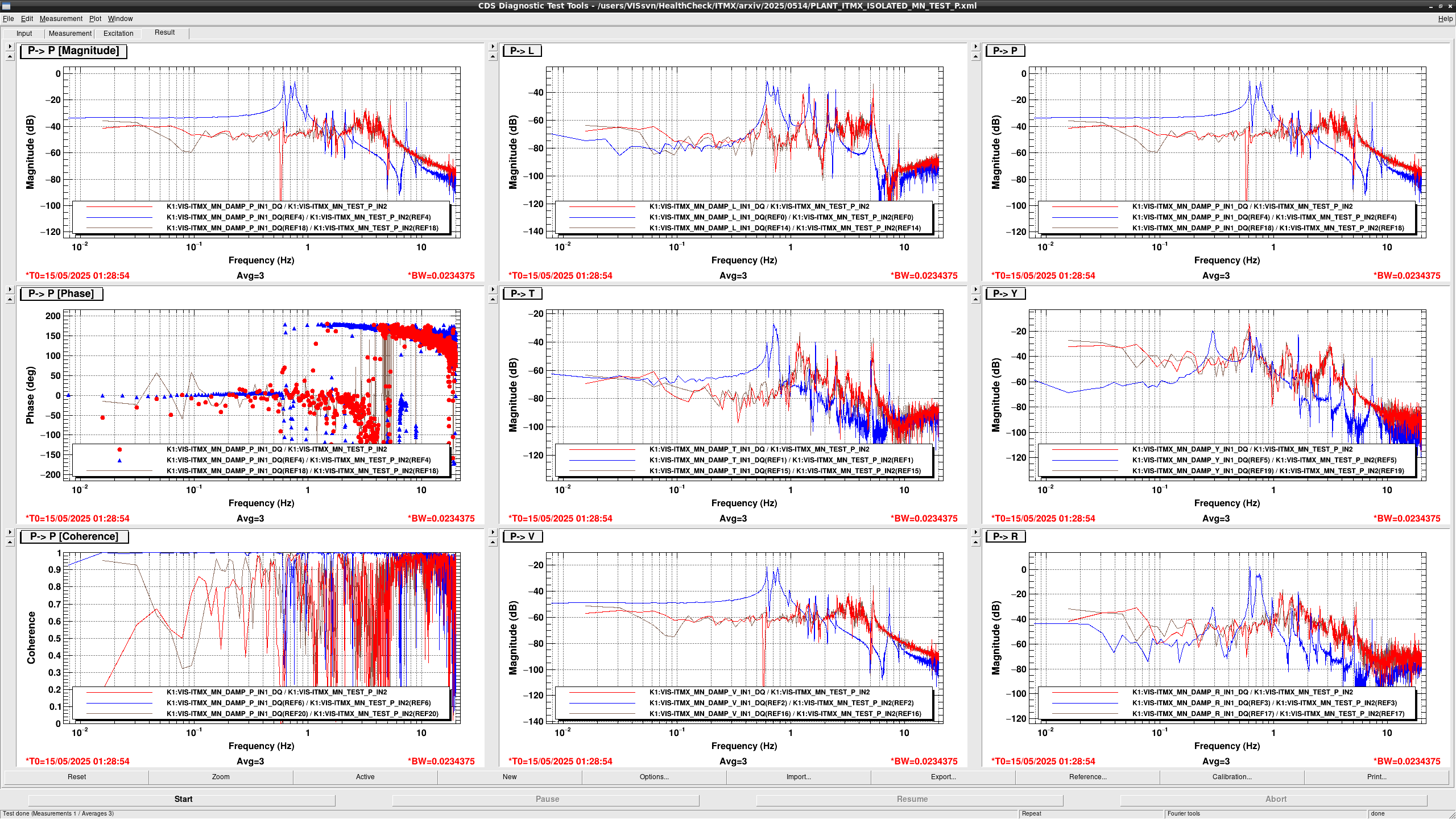
Blue curve is the healthy TF in room temperature.
Brown is when no offset is applied to MN.
Red is when P=-10000 is applied.
Note that the shadow sensor efficiency has changed by the cooling. From the difference in the free mass region (10Hz or more), the sensor efficency has increased by about 10dB when cooled.
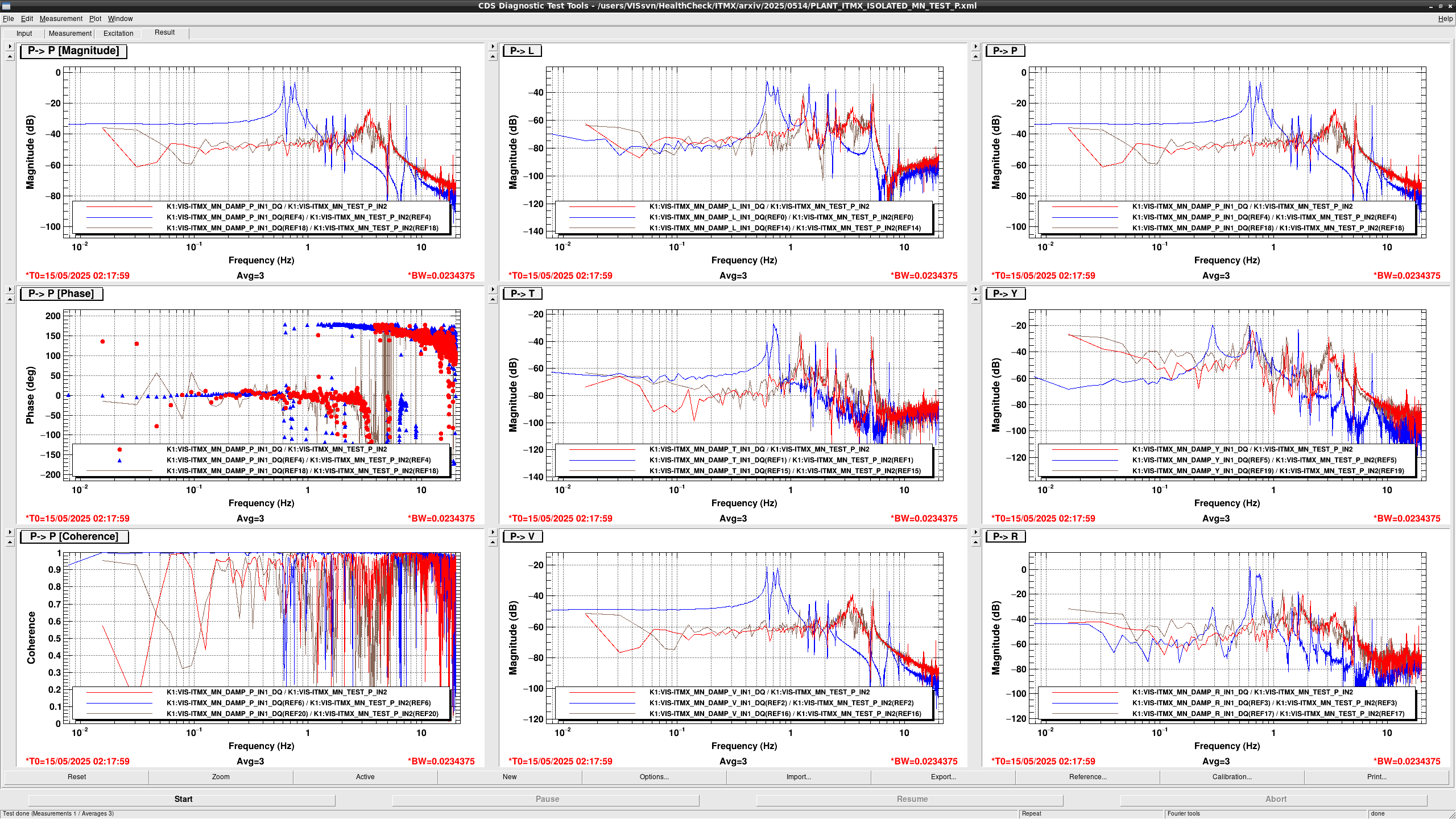
After finding this, I tried to further tilt the MN by using the moving mass in the same direction. However, the TF did not change any more.
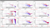
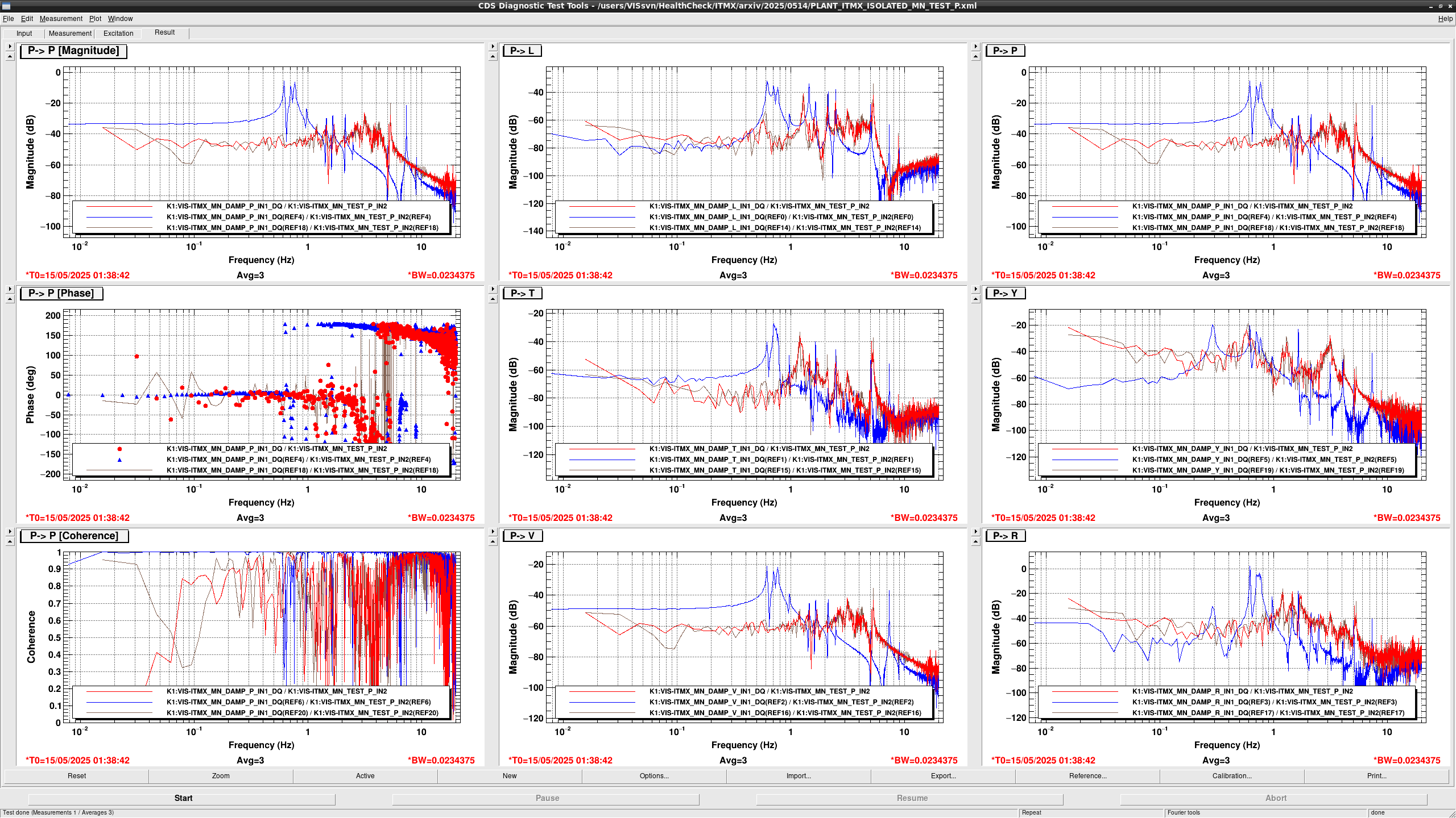
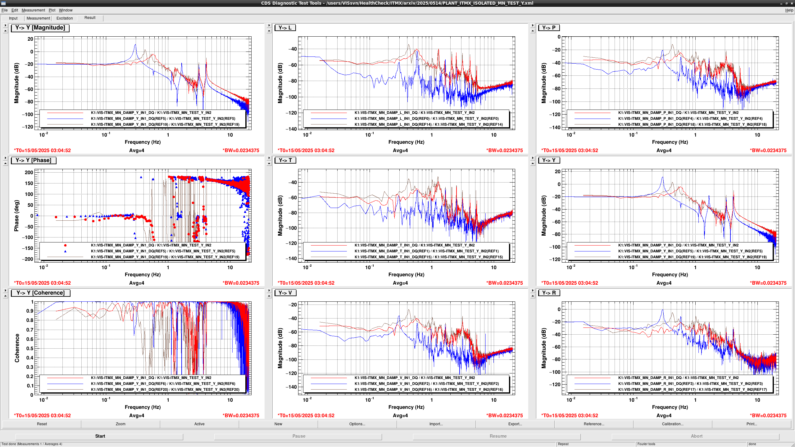
Then I reduced the Pitch offset to -5000 and used the moving mass to keep the pitch angle. This allowed me to put some offset also in Roll.
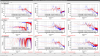
Below is when P=-5000 and R=-2000 are applied.
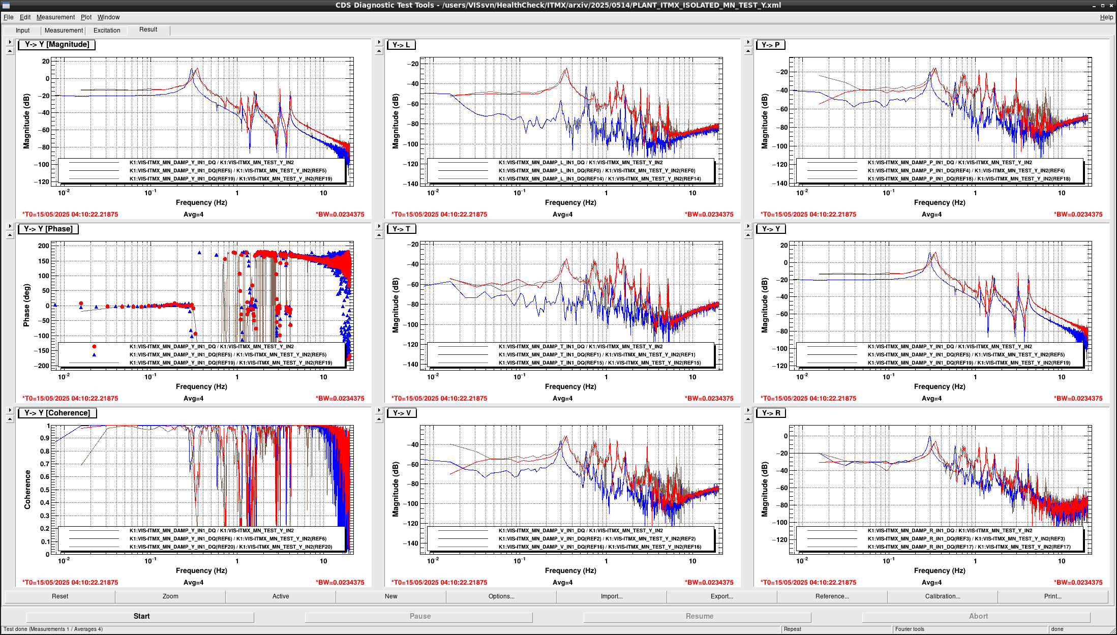
The brown curve in this figure is the TF with P=-10000.
I found that Roll does not change the TF so much. In fact, if I apply a positive offset to Roll, the 0.33Hz peak shifts to higher frequency. So Roll adjustment seem to be not effective.
While it may be possible to find a combination of offsets and moving mass positions, the TM OpLev is completely out of range in such a configuration (at least it is so when P=-10000 is applied).
Then we cannot recover the IFO alignment. Therefore, warm up seems unavoidble in anyway.
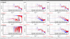
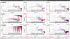
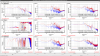
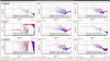
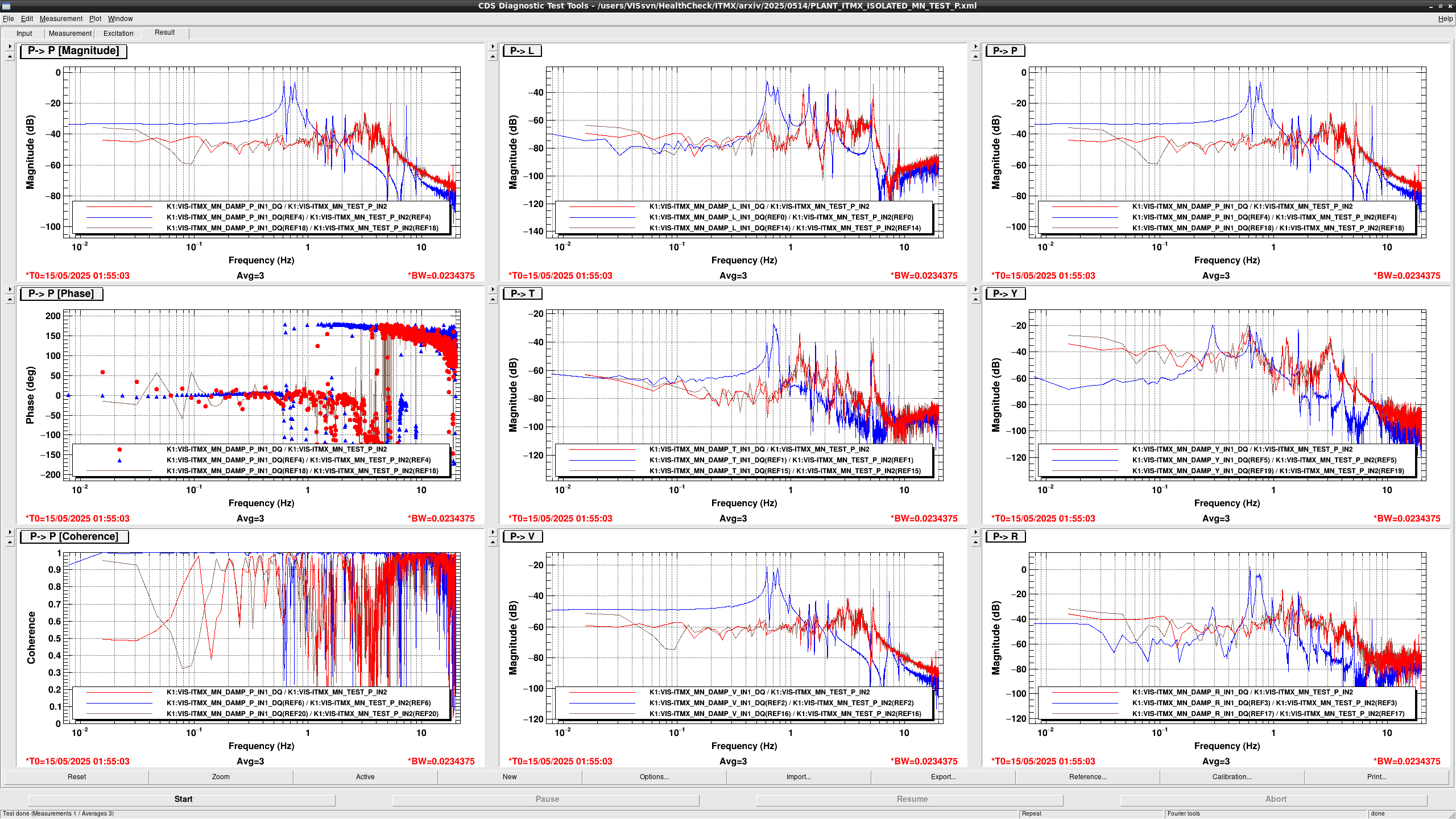
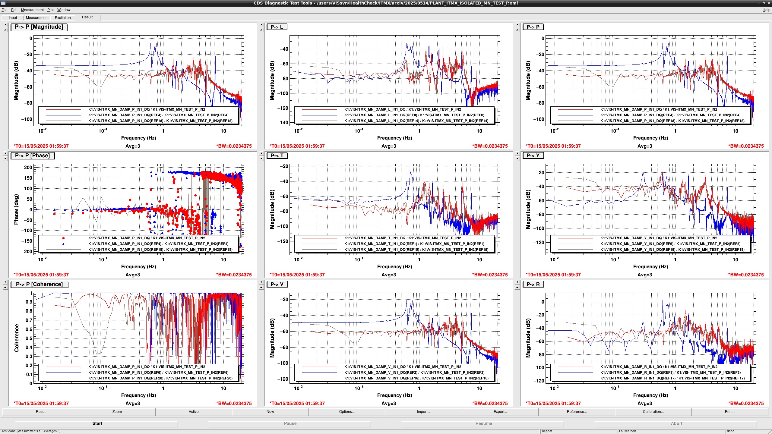
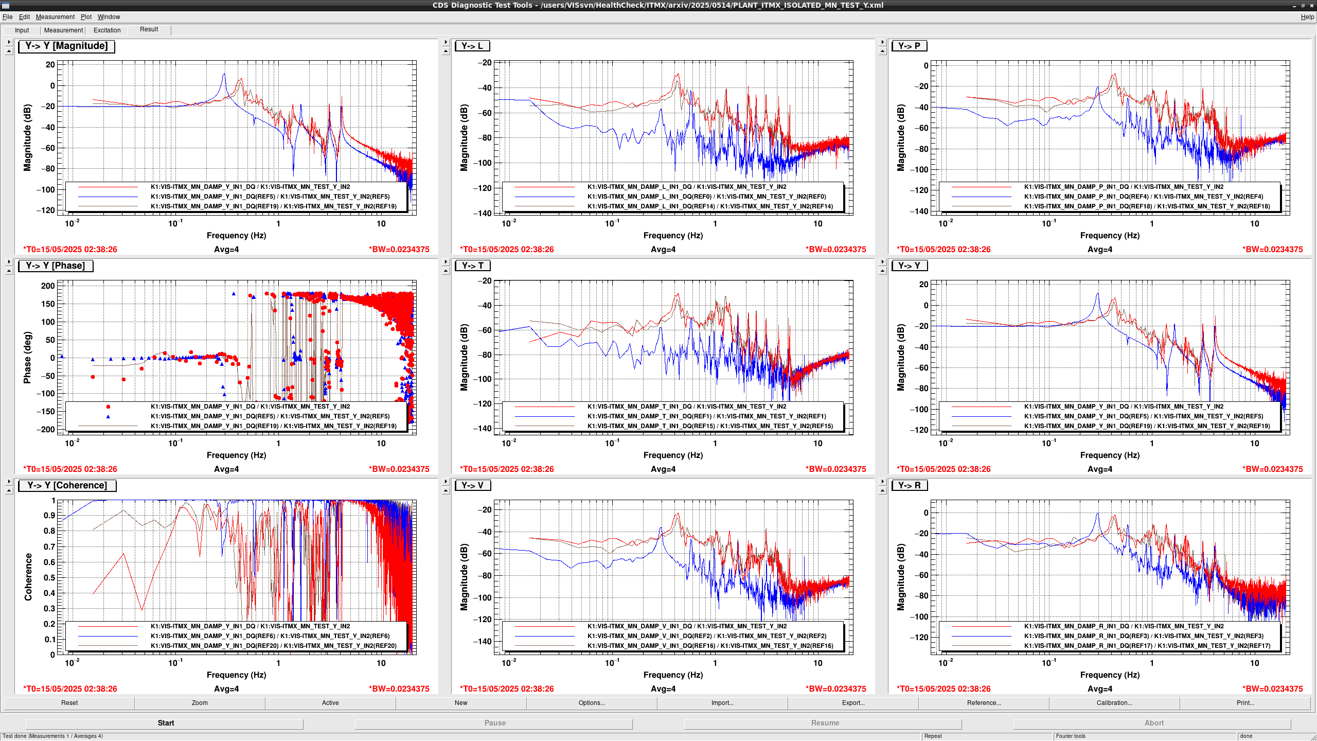
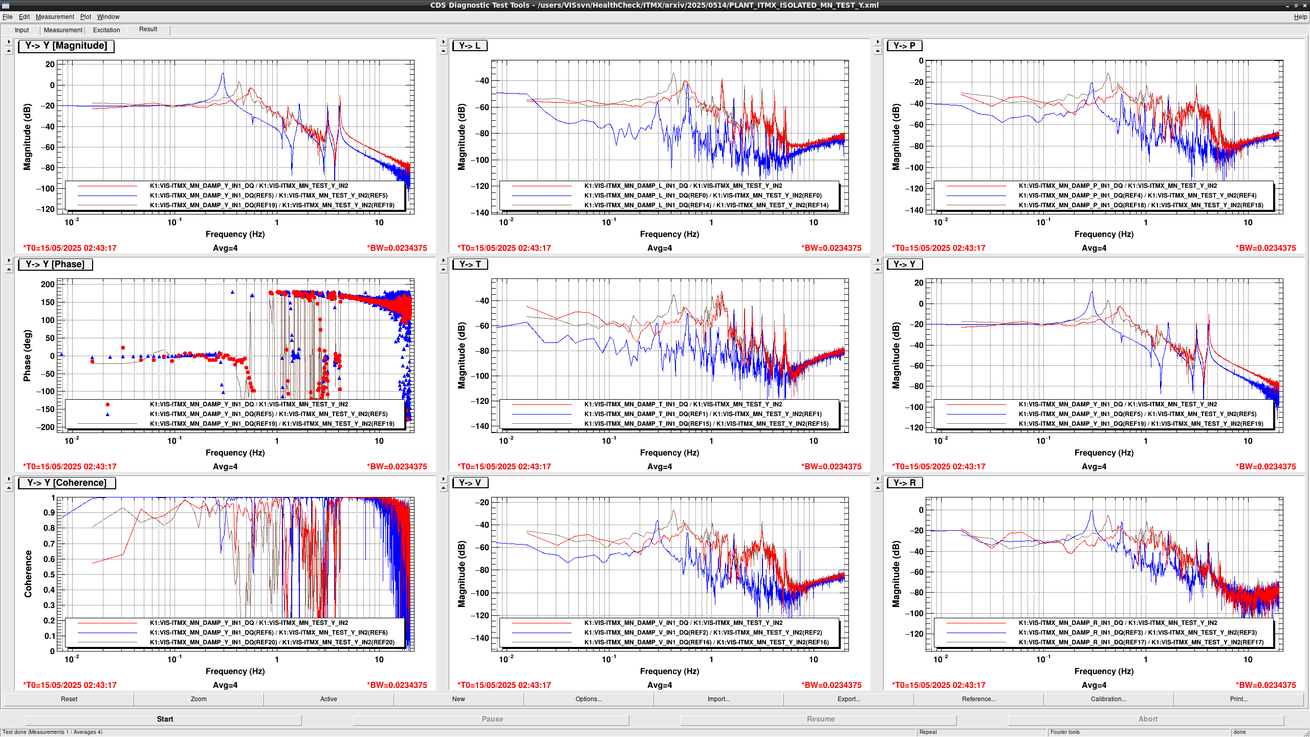
For your reference, I attached other TFs with various MN offsets (applied to the maximum value before saturating the coils).


