Dan Chen, Hido, Ushiba, Aso
Abstract
We installed a new OMC DCPD driver. We confirmed that it works fine.
Background
The OMC DCPD has two transimpedance options, Z=100 and 400.
The value of Z can be switched by sending a binary signal (ZSW) to a relay in the in-vac DCPD amplifier.
This ZSW signal was introduced to the vacuum through a separate D-Sub. This configuration induced a lot of noise, possibly due to the ground loop, into the DCPD.
Therefore, we disconnected the ZSW, which effectively fixed the value of Z to 100. However, the dark noise of the DCPD is now close to the current sensitivity. So, we wanted to change the transimpedance to 400.
For this reason, AEL made a new DCPD driver to send the ZSW signal through the same D-Sub as the other signals of the DCPD.
New DCPD driver design: https://gwdoc.icrr.u-tokyo.ac.jp/cgi-bin/private/DocDB/ShowDocument?docid=16157
S-number of the installed one: https://gwdoc.icrr.u-tokyo.ac.jp/cgi-bin/private/DocDB/ShowDocument?docid=16233
Overview of the new scheme: https://gwdoc.icrr.u-tokyo.ac.jp/cgi-bin/private/DocDB/ShowDocument?docid=16158
BIO converter
The old design used a modified BIO converter to drive the relay for the Z-switch. In the new design, the driver circuit for the relay is included in the DCPD driver circuit. So we should use the standard BIO converter.
Installed BIO converter: https://gwdoc.icrr.u-tokyo.ac.jp/cgi-bin/private/DocDB/ShowDocument?docid=10321
Conversion cable
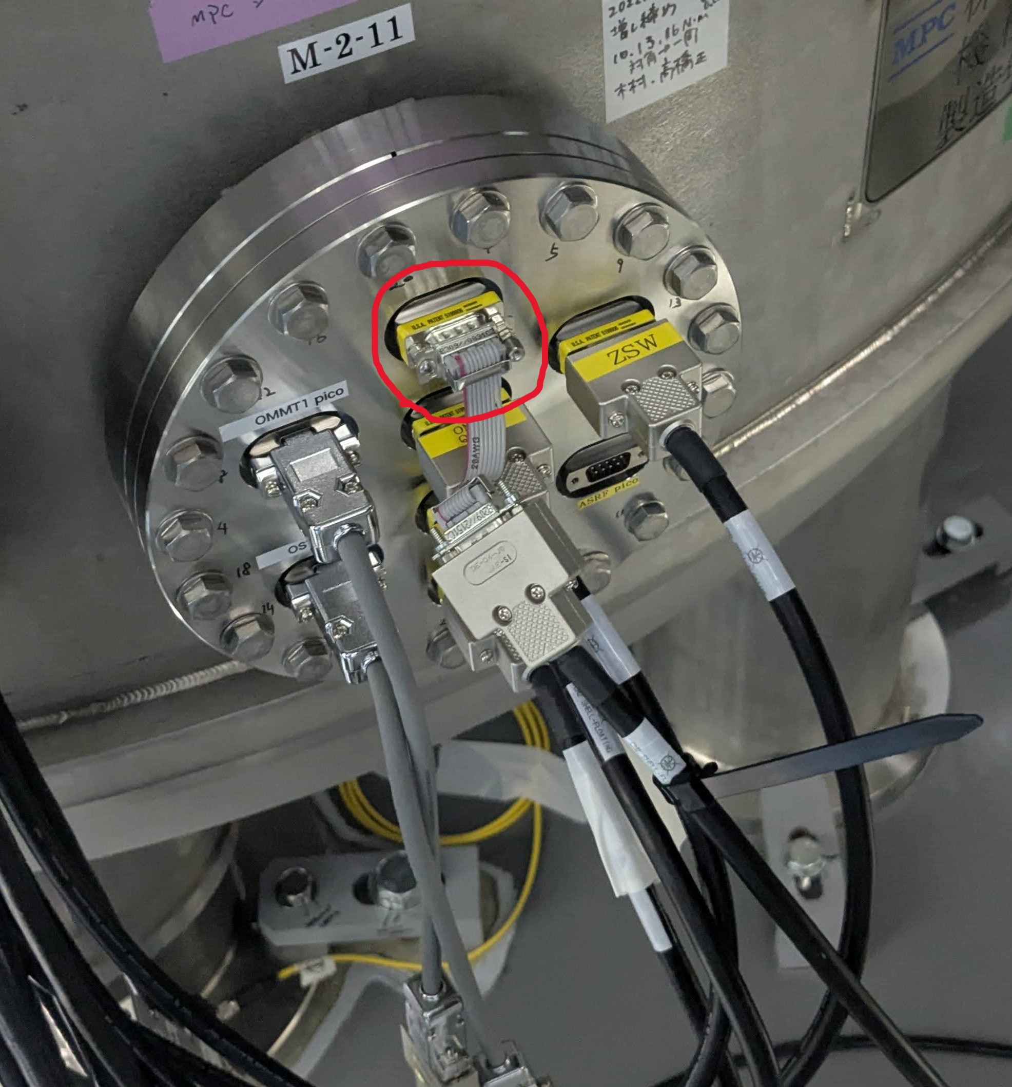
The new connection scheme requires a conversion cable in front of the vacuum feedthrough.
As shown in the photo, the current conversion cable is fragile. I used a cable tie to bind the cable to the next one so that the weight of the connector is not applied to the weak conversion cable. Still, we need to make a more robust conversion cable.
Pin-out check
Before connecting the cables, we checked each pin at the vacuum feedthrough to confirm that correct signals come to the correct pins, such as power lines and bias voltage. We also confirmed that the ZSW signal turns on and off according to the press of the EPICS button.
Noise check
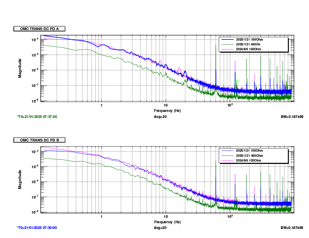
After the new circuits were installed, we measured the PD dark noise.

(/users/Commissioning/data/OMC/DarkNoise/2025/SPEC_Darknoise_OMCTRANSPD_20250121.xml)
The noise level with Z=100 is basically the same as in September last year.
When Z=400, the overall noise went down by a factor of 4, as expected.
There are several new noise peaks (~130Hz and ~250Hz) in Z=400. We don't know why they appeared.


