Reports 1-1 of 1 Clear search Modify search
MIF (General)
takafumi.ushiba - 19:23 Monday 08 August 2022 (21730) Print this report
Turn on PZT drivers and add PZT offsets for POP STM1 and STM2

Related work with klog21163.

[Toriyama, Ushiba]

Abstract:
We turned on PZT drivers and added 75 V offsets for each PZTs from DGS.
Alignment seems to come back after adding all PZT offset, so we didn't change anything else.

Detail:
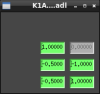
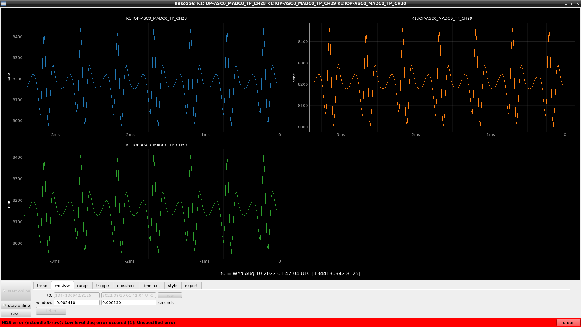
I implemented EUL2PZT matrices for STM1 and STM2 as shown in fig1.
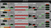
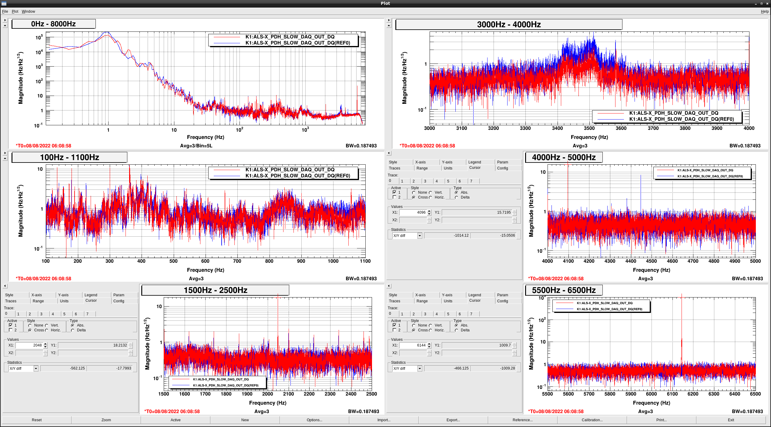
Then, I implemented calibration factor from PZT driver output voltage to corresponding DGS cnts in K1:ALS-X_IAL_STM{1,2}_PZT filter banks (fig2).
Since 0V (0 cnts) - 10V (2^15 cnts) are corresponding to 0V - 150V, a calibration factor is (2^15)/150 = 218.45 cnts/V.
Thanks to this calibration factors, we can set the offset of the filter banks as the voltage that we would like to apply to the PZTs.


We connected PZT drivers to AC power supply, which is used for PDA1 of fiber output monitors and prepared inside the POP table.
After that, we turned on PZT drivers and set analog outputs from the driver to zeros.


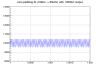
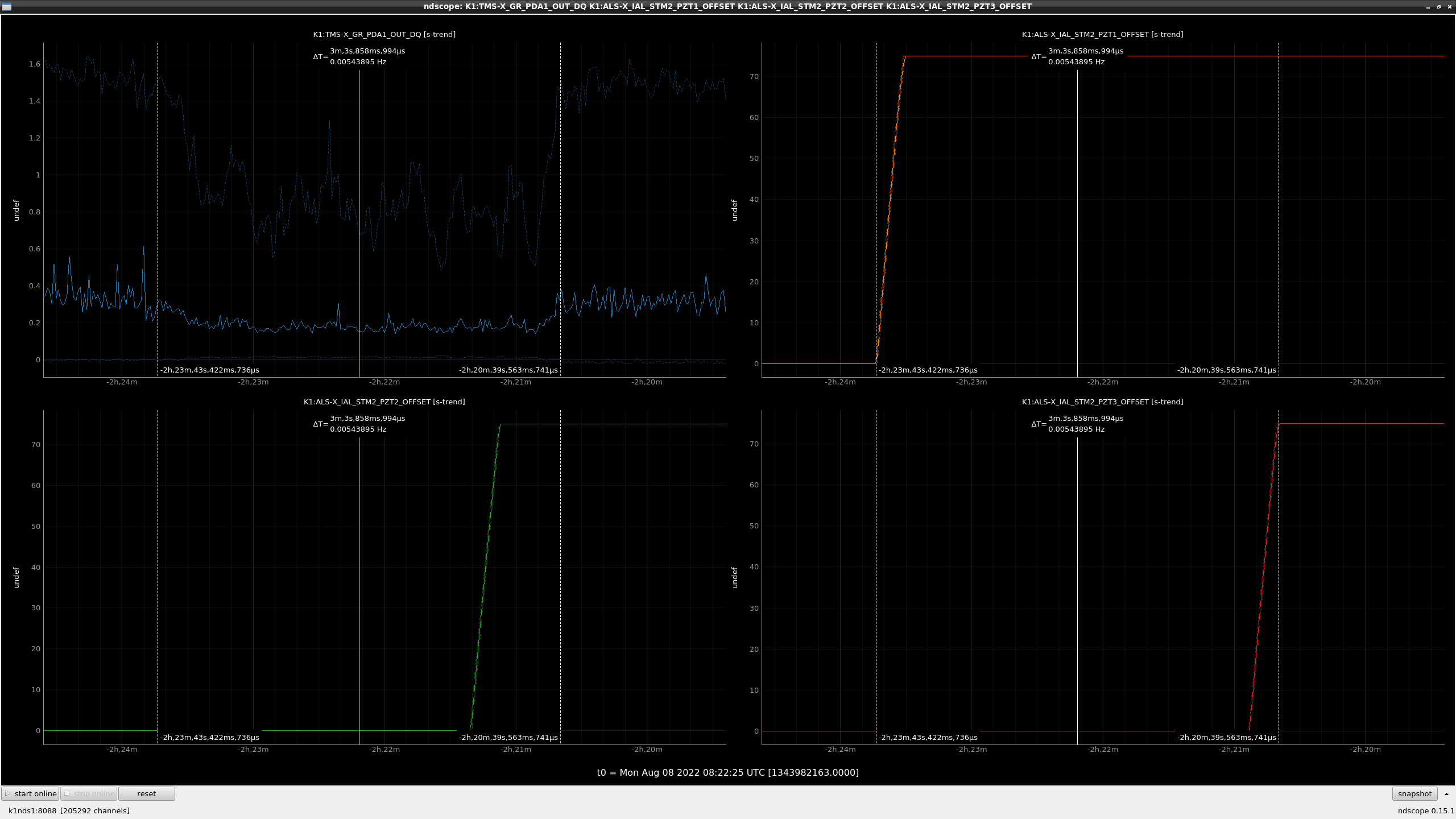
First, we added offsets for PZTs of STM2 one by one.
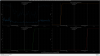
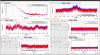
Figure 3 shows the time series data of transmitted GRX signals during the work.
As you can see, transmitted light power once go down but come back after all offsets were added.

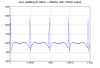
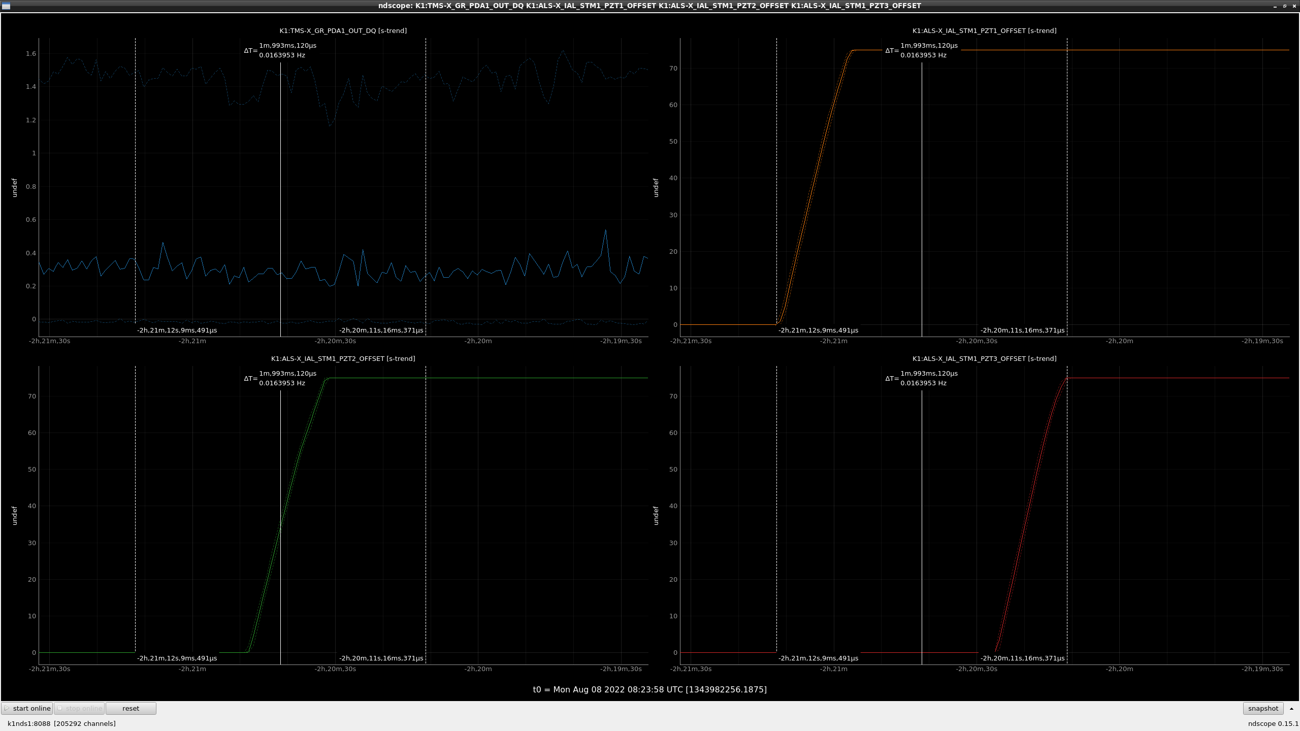
In the same way, we aded offsets for PZTs of STM1 one by one.
Figure 4 shows the time trend of  transmitted GRX signals during the work.
In this time, we cannot see any significant drop of the signals.

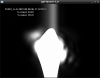
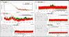
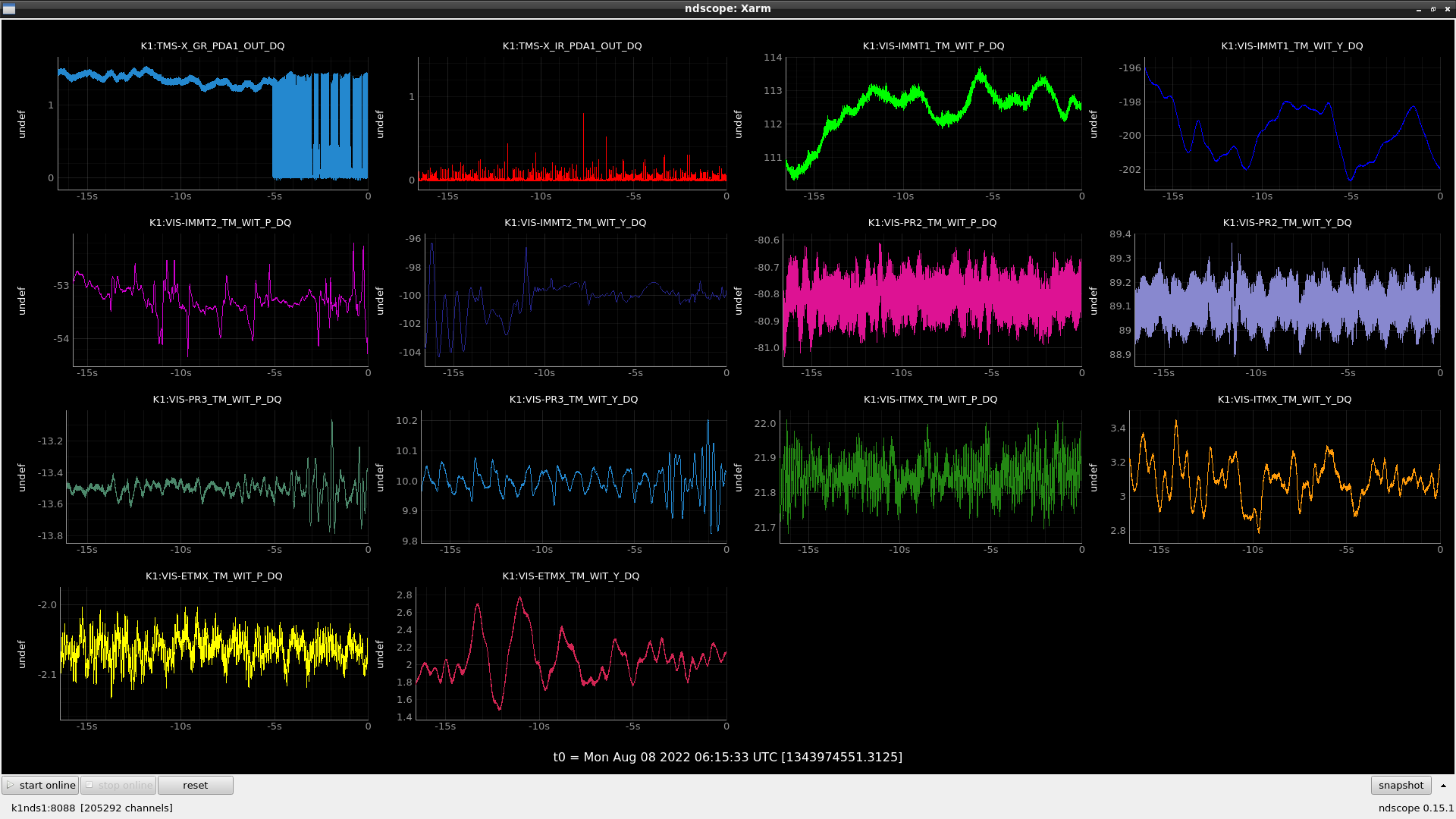
After that, I requested the XARM guardian to ALS_LOCKED state and then we can lock XARM with TEM00 (fig5).
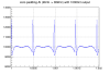
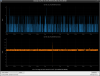
Since the transmitted light power didn't change so much (~1.5: fig6), we didn't perform any additional alignment workafter adding PZT offsets.

Note:
As I wrote, PZT drivers are connected to the same power supply for PDA1 of fiber output monitor now.
I'm not sure it shold be avoided but even if so, we don't have to hesitate changing PZT driver power supply because we confirmed PZTs don't affect the alignment so much if we move all of them at the same time.

Tanaka-kun kindly calculated how much beam spot change is expected due to this work and it seems negligible.
Detail will be reported by Tanaka-kun.

Images attached to this report
Comments to this report:
kenta.tanaka - 20:28 Monday 08 August 2022 (21732) Print this report

## Abstract

I calculated the beam position displacement on ITM with ABCDEF matrix. According to PZT specsheet, PZT applied at 75V pushes the mirror forward 1.8 um (= 3.6um/150V*75V). When STM1 and STM2 pushed the mirror forward by 1.8um each, the beam spot position on the ITM shifted ~0.1 mm from the position before pushing.

### How to calculate it

  • The propagation of rays in a system slightly misaligned from the ABCD system is calculated with the matrix called "ABCDEF matrix", which is an extension of the original 2x2 ABCD matrix to a 3x3 matrix by adding a shift of the beam position due to misalignment to the elements (1,3), a tilt of the optical axis due to misalignment to the elements (2,3), and (0,0,1) in the third row.
  • The ABCDEF matricies of free space propagation, reflection from a displaced and misaligned mirror and thin lens is represented as below.
    • free propagation L^free=[1l0010001]\hat{L}_{\mathrm{free}} = \left[ \begin{matrix} 1 & l & 0 \\ 0 & 1 & 0 \\ 0 & 0 & 1 \end{matrix} \right]
    • reflection from a mirror R^mirror=[102Δxsinθ-2Re12Δα001]\hat{R}_{\mathrm{mirror}} = \left[ \begin{matrix} 1 & 0 & 2\Delta x \sin \theta \\ -\frac{2}{R_e} & 1 & 2\Delta \alpha \\ 0 & 0 & 1 \end{matrix} \right]
    • thin lens F^lens=[100-1f10001]\hat{F}_{\mathrm{lens}} = \left[ \begin{matrix} 1 & 0 & 0 \\ -\frac{1}{f} & 1 & 0 \\ 0 & 0 & 1 \end{matrix} \right]
      • where l is distance in the free space, Δx\Delta x is lateral shift of a mirror, θ\theta is an incident angle to a mirror, ReR_e  is an effective radious of curvature of a mirror, Δα\Delta \alpha is a misaligned angle of a mirror and ff is a focus length of a lens (c.f. Siegman "Lasers" chap. 15)
  •  The ABCDEF matrix from STM1 to ITM is as below
    •  M^=L^pr3itmR^pr3L^pr2pr3L^pr2GrL3F^GrL3L^GrL3GrM3R^GrM3L^GrM3GrM2R^GrM2\hat{M} = \hat{L}_{\mathrm{pr3itm}} \hat{R}_{\mathrm{pr3}} \hat{L}_{\mathrm{pr2pr3}} \hat{L}_{\mathrm{pr2GrL3}} \hat{F}_{\mathrm{GrL3}} \hat{L}_{\mathrm{GrL3GrM3}} \hat{R}_{\mathrm{GrM3}} \hat{L}_{\mathrm{GrM3GrM2}} \hat{R}_{\mathrm{GrM2}}
  • Assuming that the ray vector before shifting is r0=[00]r_0 = \begin{bmatrix} 0 \\ 0 \end{bmatrix}, and that STM1 and STM2 are shifted forward by 1.8um (= 3.6 um /150 V * 75 V) each and no misalignment has occurred, the beam shift on the ITM is equal to M(1,3).
    • M(1,3) ~ 0.1 mm
    • R_e
takahiro.yamamoto - 20:57 Tuesday 09 August 2022 (21743) Print this report

[Ushiba, YamaT]

After this work, 2048Hz and its harmonics (4096Hz and 6144Hz) appears on the control signals of Gr PDH-X and ALS DARM as shown in Fig.1.
Blue and red curves represent before (around 9:00 on 8/8 JST) and after (around 15:00 on 8/8) spectra, respectively.
There is no line on 1024Hz and 3072Hz. So it seems to be a series of 2048Hz.

When we took the red curve, PZT output is 75V (~16384ct) as the offset form DAC output.
And these lines can be removed by changing the DAC output as 0ct (0V).
So the output to POP PZT induces these lines.

Because lines lie just 2048, 4096, and 6144Hz with the frequency resolution as 0.125Hz.
So it seems to be caused from digital issue not from PZT itself, circuits etc.

Tomorrow, Ushiba-kun will check the output signals from Dsub-BNC converter to check that
a cause lie around digital side or PZT side just in case.

We set PZT offset as 0 for today.

Images attached to this comment
takafumi.ushiba - 11:07 Wednesday 10 August 2022 (21747) Print this report

[Yasui, Ushiba]

We checked DAC outputs from corresponding channels and found that there are strange 2048-Hz signals in the DAC output itself (fig1).
During ths measurement, we disconnected the BNC cables between DGS rack and PZT drivers, so it is not likely to be related GND of the drivers.

Images attached to this comment
takahiro.yamamoto - 14:04 Wednesday 10 August 2022 (21749) Print this report

It comes from the digital AI process between user models and IOP models.

On real-time system, default implementation of the digital AI process is 0-padding way.
FIg.1 shows a simulated signal on the 65kHz IOP model when a 2kHz user model outputs 10000ct offset.
We can see a periodical (2kHz) glitch like signals.
By decreasing offset value on the user model, an amplitude of the glitch like signal also decrease (See also Fig.2 with 1000ct offset).
Peak amplitude of these glitches seems to become ~27% larger than the given DC offset value.

We have two choices to avoid this noise.

One is to change the model rate from 2kHz to 16kHz.
A simulated signal on the IOP model when 16kHz user model outputs 10000ct offset is shown in Fig.3.
In this case, 16kHz noise is induced but peak amplitude can be suppressed as ~4% of the given DC offset value.
Thanks to the response of cavity, PZT, etc. noise around 16kHz may be practically negligible.

Another choice is to use "no_zero_pad" option on the user model.
In this case, we can completely remove this kind of noise. But CPU load increase.
Fortunately, CPU load is not so serious because k1ial is now very small model.
(It can be used on very large model e.g k1lsc, k1asc, and so on.)

I haven't used this option and seen it also on LIGO's models yet.
So we should test it if we choose the latter choice.

Images attached to this comment
takahiro.yamamoto - 10:26 Monday 22 August 2022 (21842) Print this report

Digital related noise as 2048Hz harmonics were able to be removed by adding 'no_zero_padding' option of the real-time model (See also Fig.1).
CPU load doesn't seem to increase by this change as shown in Fig.2.

----
Fig.1 shows spectra of the Green PDH-X signal before (green) and after (red) this work.
- 2048, 4096, 6144Hz lines were vanished.
- Noise floor level of 1-20Hz were improved but it is probably not related to this work (by modifying local damping control?)

Images attached to this comment
Search Help
×

Warning

×