Uraguchi, K. Tanaka, Simon, Akutsu before lunch on 7th June 2019:
Summary
Improved the alignment of the BRT optical table on/plus the TMS-VIS with respect to a transmitted green beam at Y-end. We thought the first alignment of the BRT yesterday was not so bad, but that was just to let it sit on, so we would like to charange whether we could improve that more or not.
To put the summary of the procedure,
- Fix the TMS-VIS table, and loosen screws for fixing the three feet of the BRT optical table, and loosen screws for fixing a pair of plates to hold a frontal positioning pin (there are two positioning pins to integrate the BRT optical table and the TMS-VIS; one is at the center, and another is at the front side close to the primary lens of the BRT).
- Crane up the BRT optical table very very slightly. Don't forget the purpose of the craning is just to deposit most of the weight of the BRT optical table so that we can tweak the table easier by hands. (Probably we need a traverser-like system.)
- Rotate the BRT table somehow. Seems two people are required, but probably a single people might be able to rotate it.
- Crane down the BRT, and fix all the screws
- Release the TMS-VIS.
Details
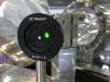
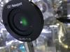
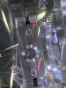
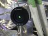
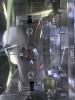
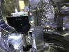
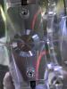
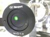
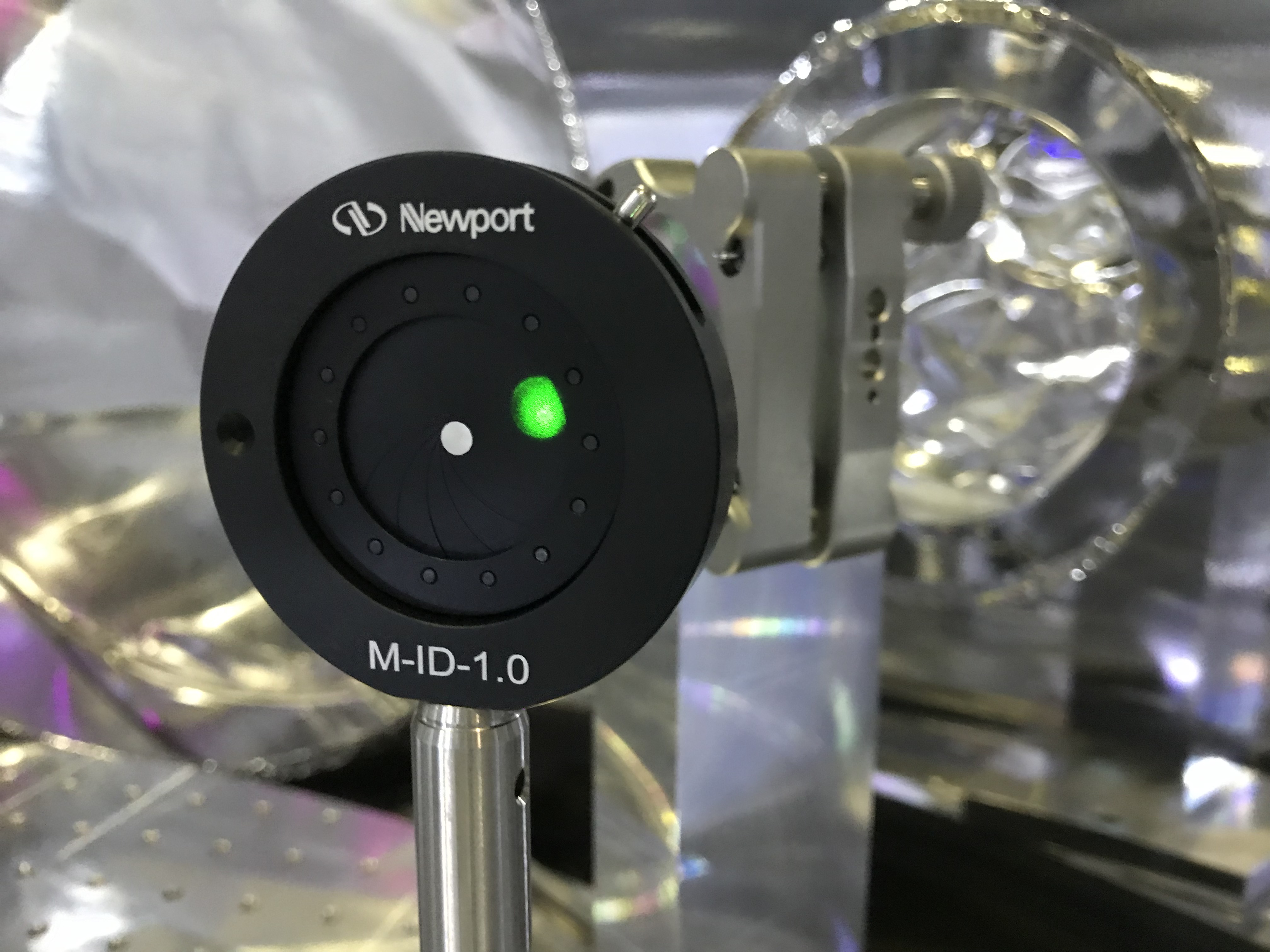
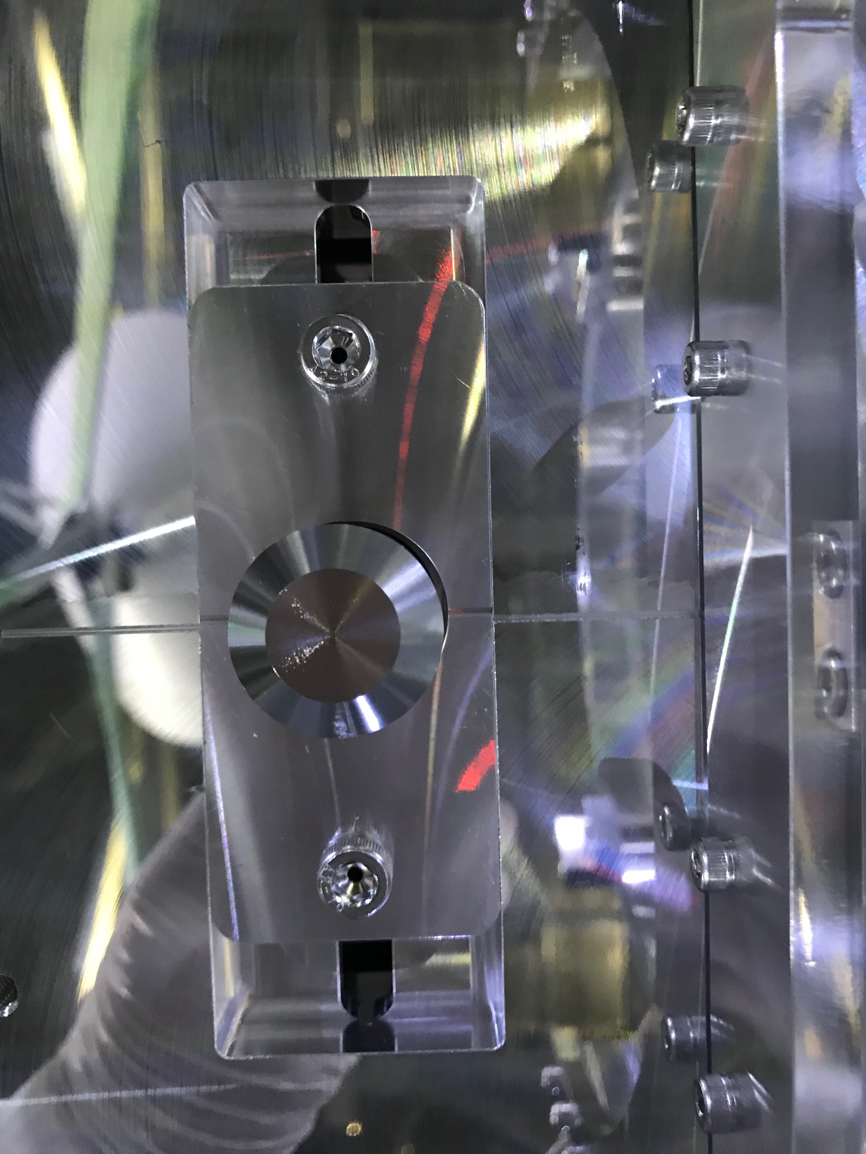
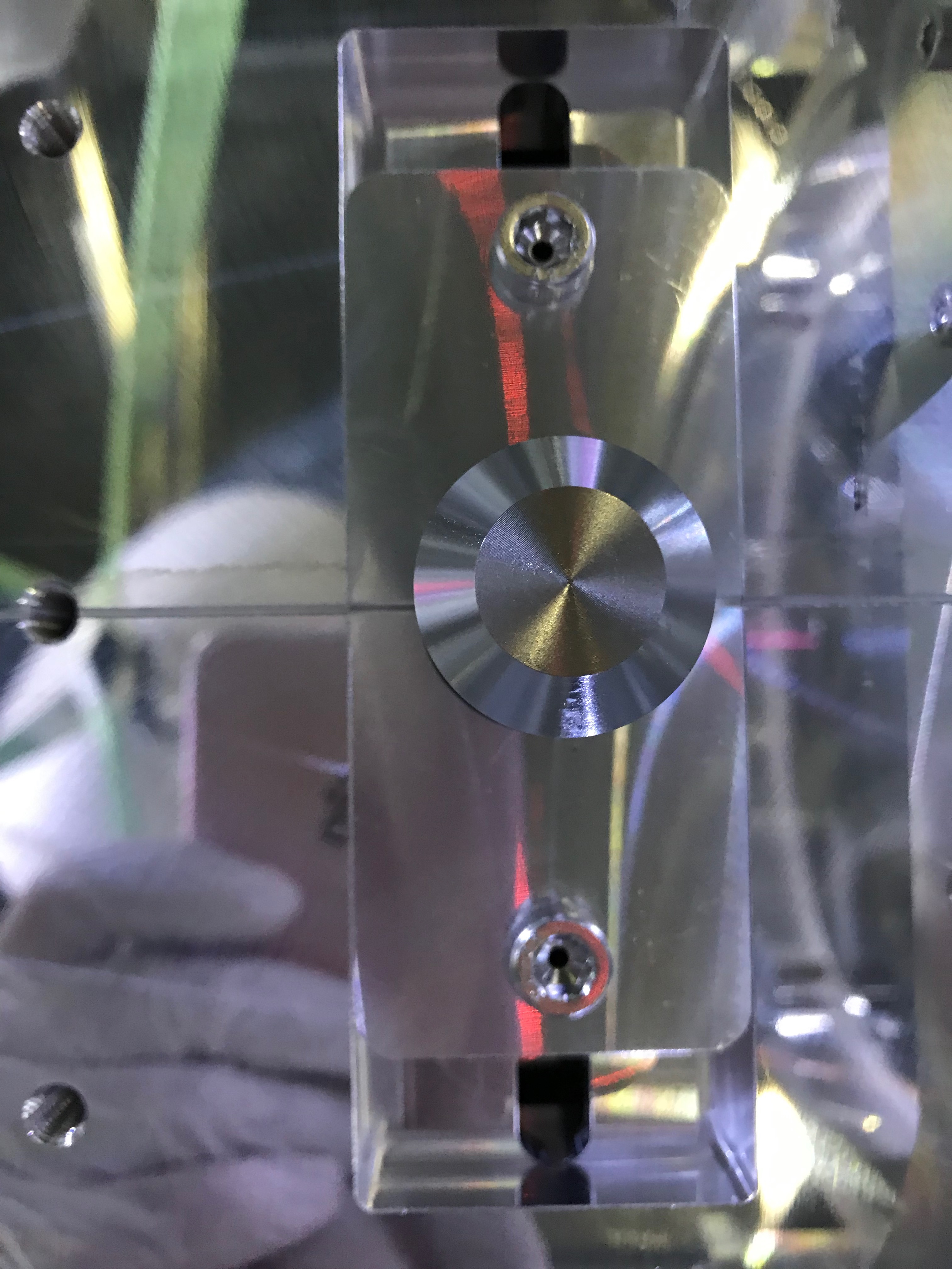
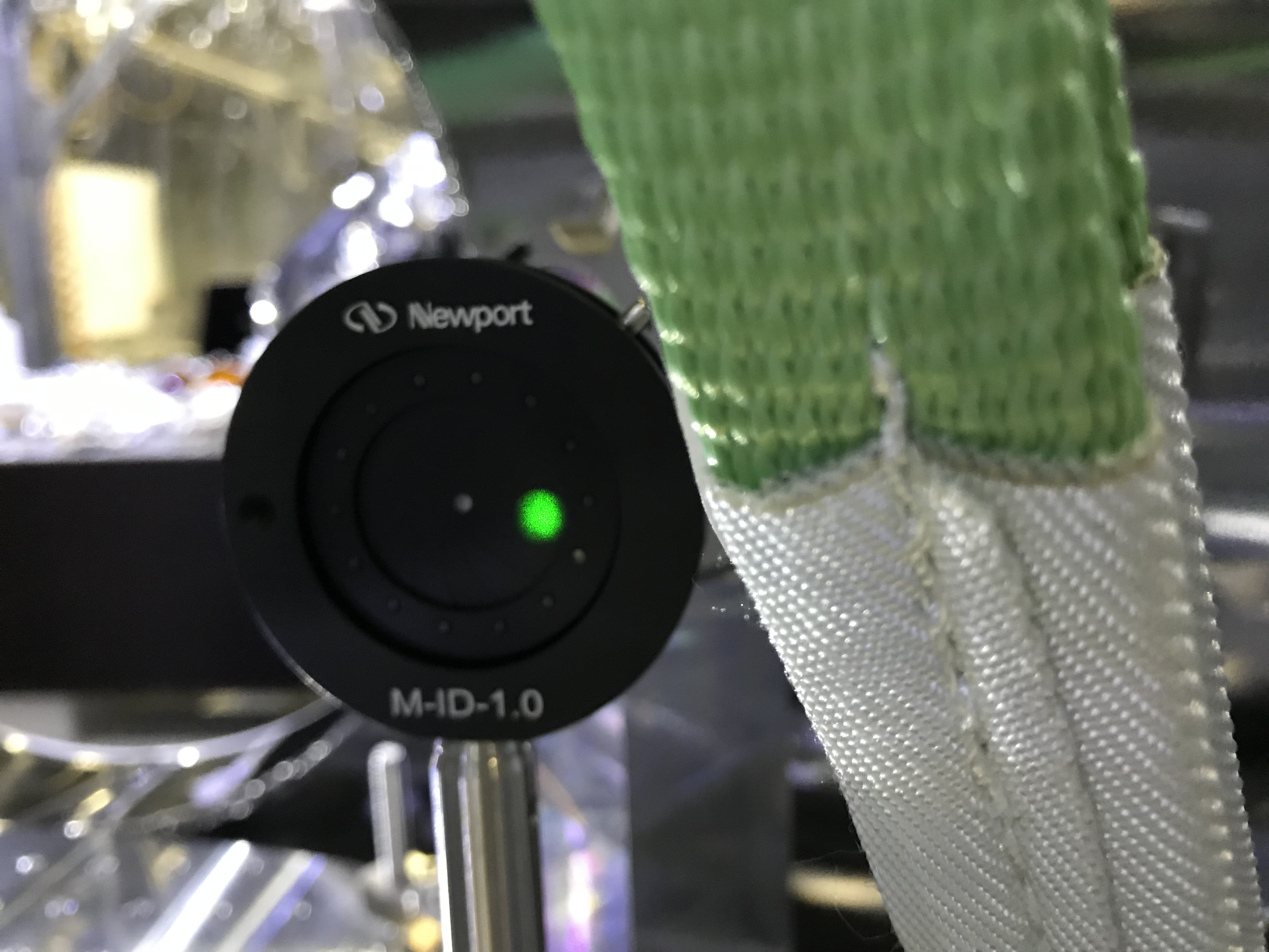
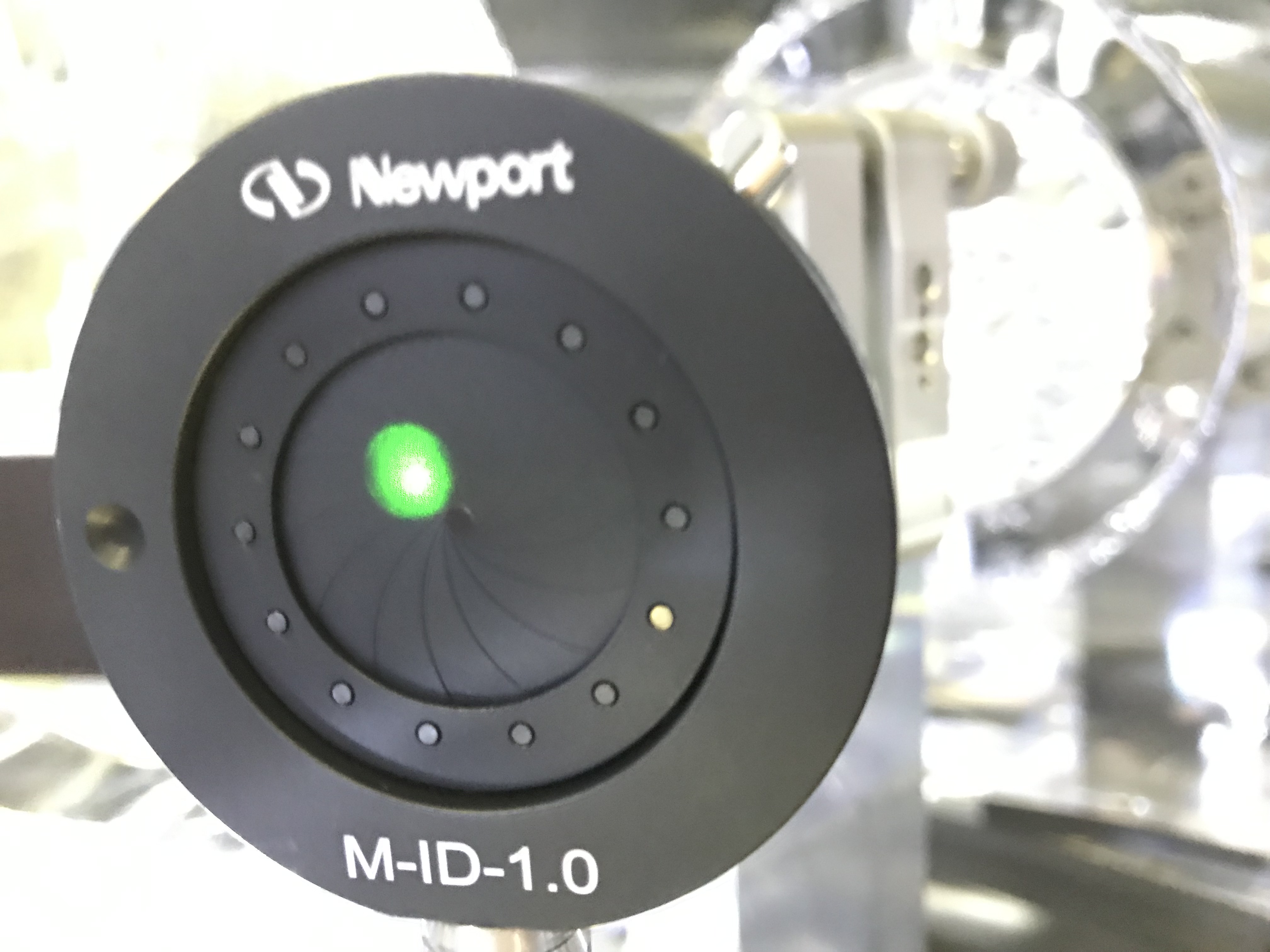
Procedure 1: the following is the first procedure of us. Before doing this, the beam spots looked like in Fig 1 (in front of the 2ndary lens) and 2 (behind the 2ndary lens). The relative location of the frontal pin and the pair of plates is shown in Fig. 3.
- Uraguchi-san fixed the free-swinging TMS-VIS's suspended table. Note that the fixtures at the three points were not the same each other...depending on the gaps between the suspended mass and the base structre. The accessibility to the work places in the chamber seemd so tough.
- Then we loosen screws for fixing three feet of the BRT optical table so that it became separatable from the top plate of the TMS-VIS.
- Attached shuckles to four eyeblots on the BRT optical table, and connected slings to the shuckles.
- Then we SLIGHTLY craned up the BRT optical table. Actually slightly. Uraguchi-san somehow triggered/excited/tweaked the table to know the levitation. (I don't know the most proper English verb here)
- After loosening two screws that fix a pair of plates to hold a front-head pin (the pin closer to the first lens), I and Uraguchi-san somehow rotate in yaw the BRT rotation clockwise. The rotational direction was understood by compairing some beam spots after the 2nd lens and handy-input actuation; I, in advance, had slightly moved the free BRT optical table by hands to learn which way (direction) to go.
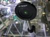
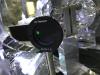
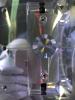
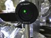
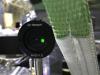
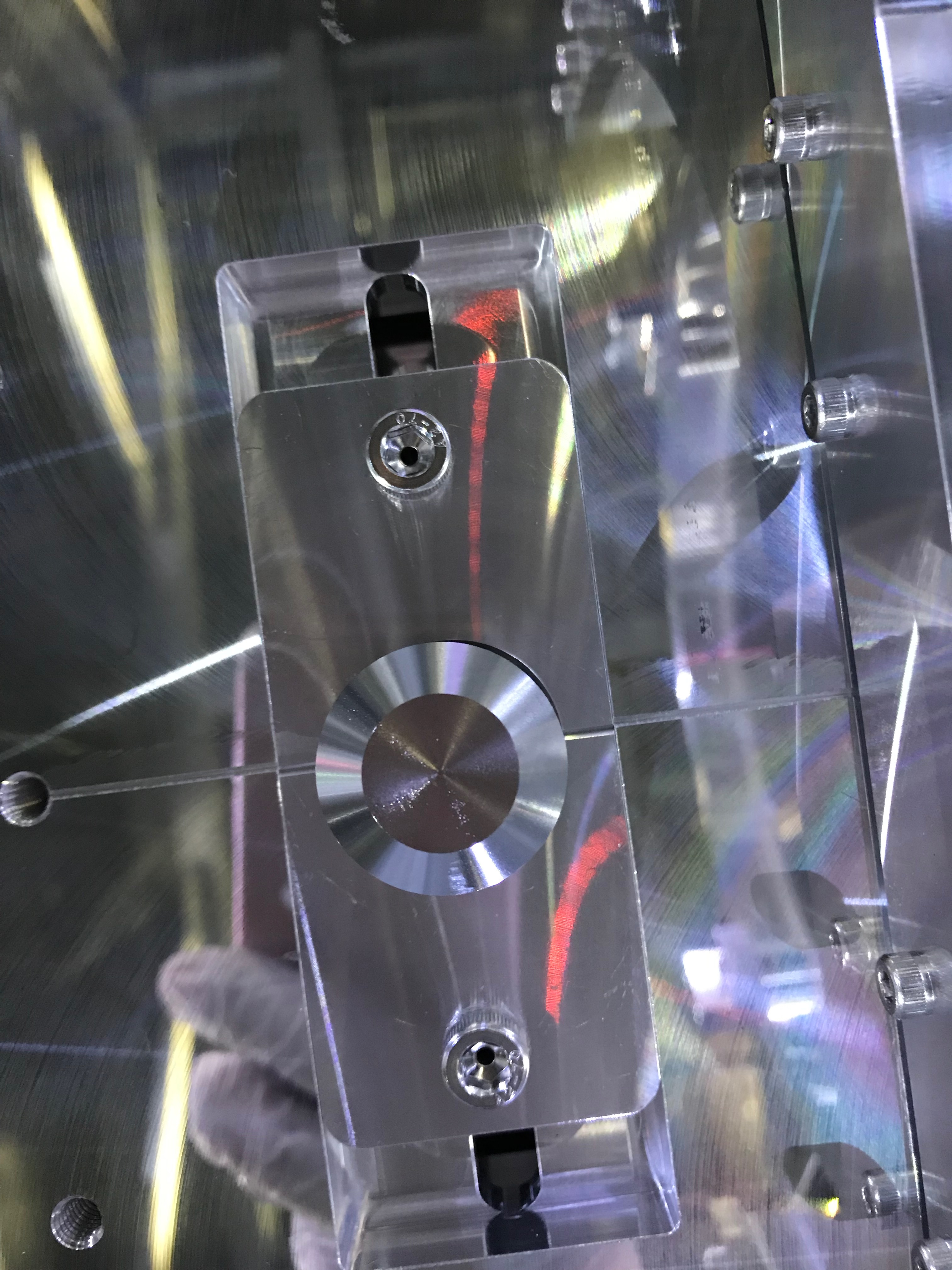
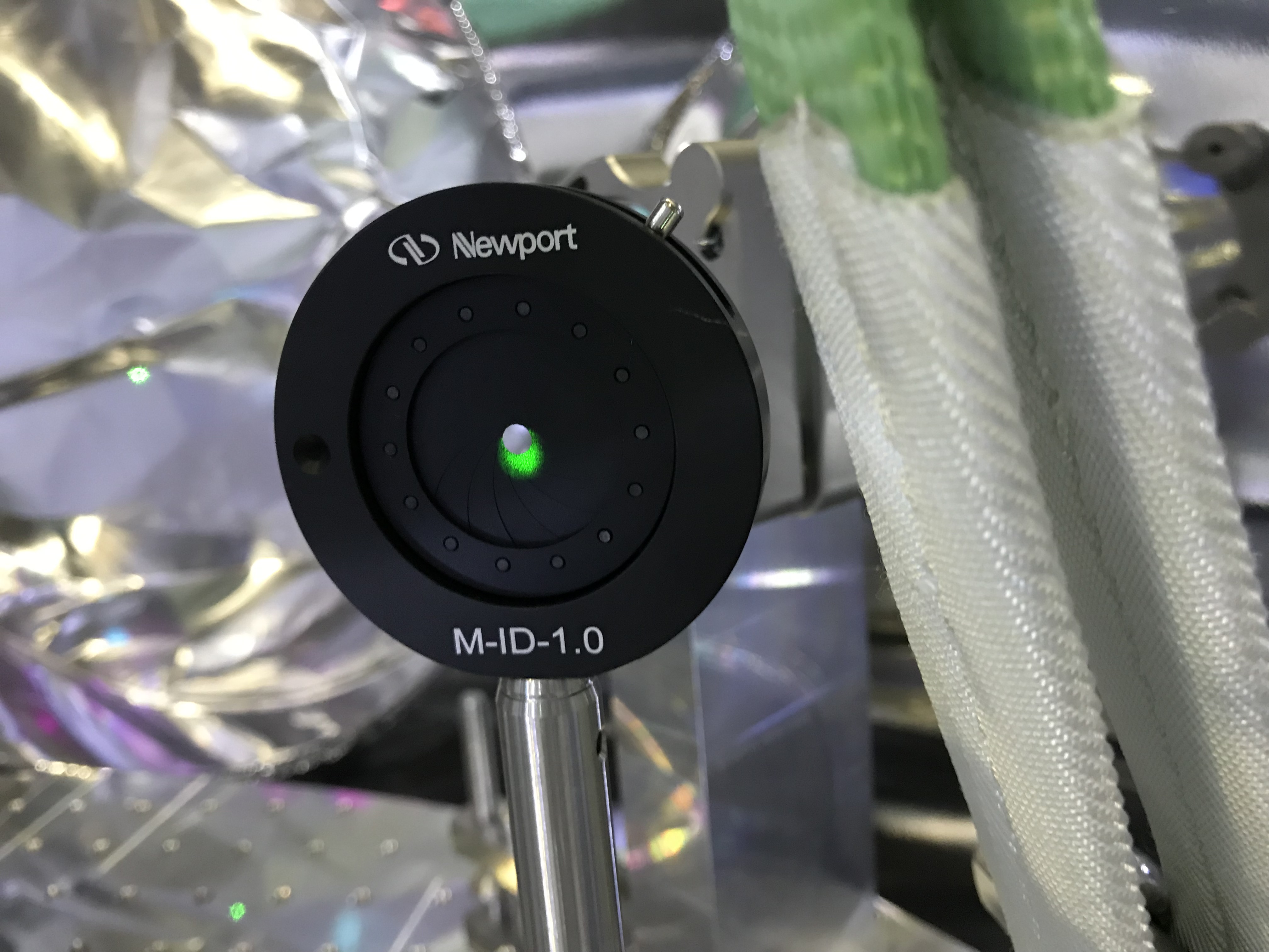
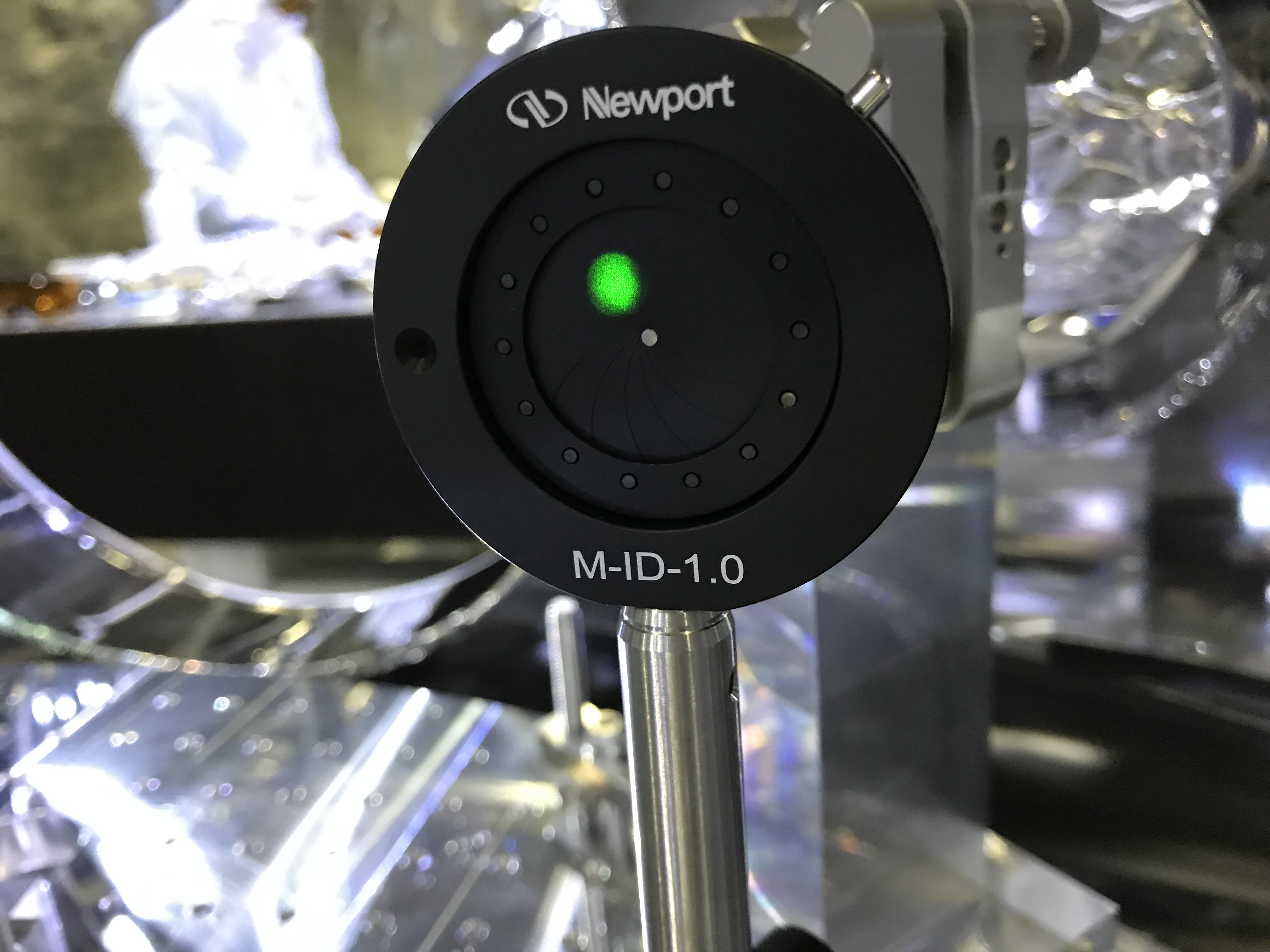
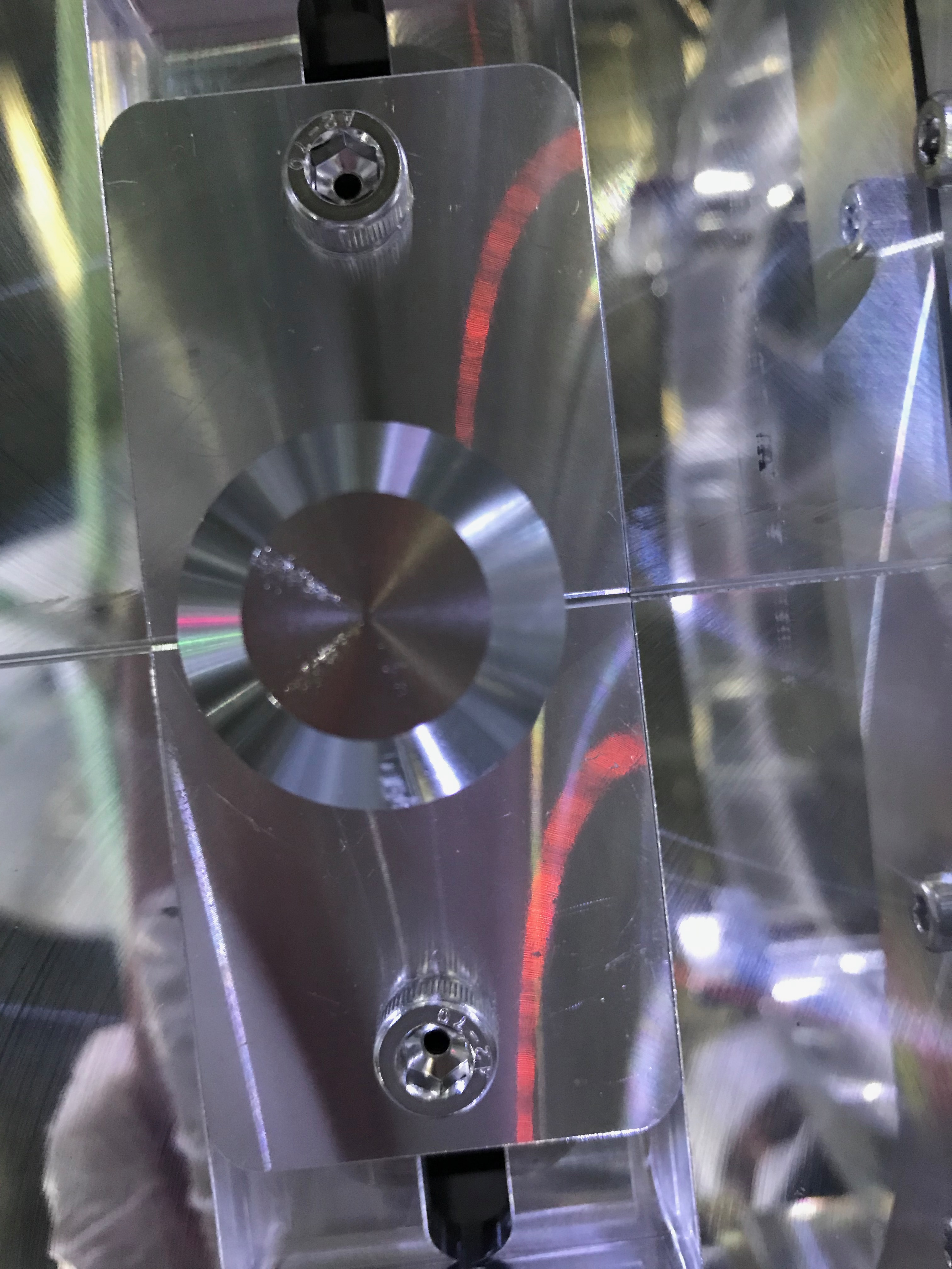
- Putting an iris several-where, I checked the beam position by trying the rotation (Fig 4 and 5), and decidied the alignment of the optical table. The resultant situation around the frontal pin is shown in Fig 6, and compare it with Fig 3.
- After the rotational trial, we fixed the BRT optical table, but we immediately found we did too much; the beam spots were moved over our expection after the TMS-VIS was released (Fig 7). Well actually, we had been worried about this would happened; the fixed position and released/balanced position of the TMS-VIS were slightly different, and the BRT is so sensitive to change the beam positions with respect to the amount of the difference.
Procedure 2: ok, we did too much...
- We learned the amount-ish of the rotation to be done. And we decided to rotate it back to some extent in the opposite direction (Fig 8), and...
- Did jambo-manbo (Fig 9), then,
- Ok, it came back slightly (Fig. 10) but I felt still we were able to improve more.
Procedure 3: the final
- We did the work again. This time, the amount of the rotation was so small that I and Uraguchi-san felt that it was not moved (Fig 11), but at the same time I felt we sufficiecntly rotated. The beam spot at the fixed state is shown in Fig 12.
- After releasing the TMS-VIS, the spot was at -4mm? to X and +4mm? to vertical (Fig 13); considering the leverage effect of the BRT optics for the angles of the input light beam, I thought this would be a kind of limit that we human beings could, so we stopped.
Then we fixed the three feet of the BRT optical table, and the plate pair holding the frontal pin.
Notes to the future
- By the way, before doing the procedure 1, we would like to fix the dummy/ballast masses on the BRT optical table, but unfortunately some screw parts were missing, and we could only fix a set of them... Needed to be dealt later.
-
I dropped a bolt for the shuckle in the chamber and it was deep into the bottom so I could not reach it. It was left so far...
