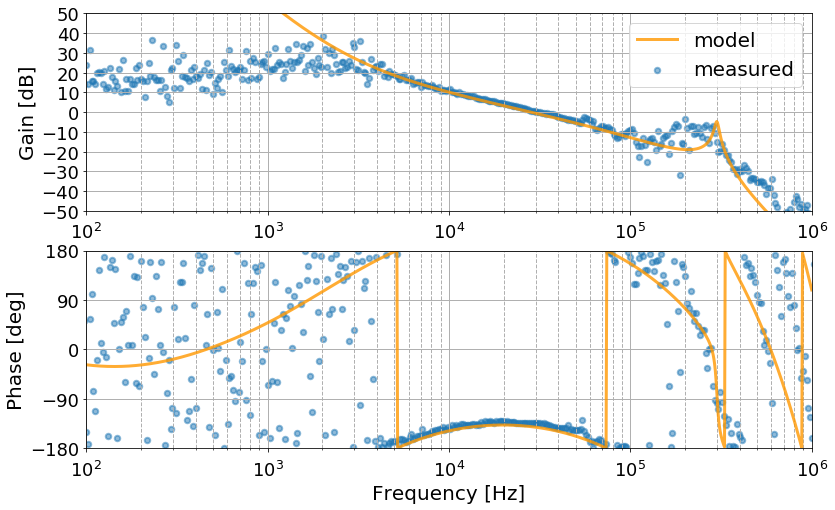
I compared the OLTF of PLLY measured on 2/15 with the calculat model.
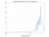
The transfer function model takes into account the the servo filter, PFD, actuator efficiency, and the resonance of the laser PZT and time delay.
The resonance frequency of PZT was set to 300 kHz, and the Q factor was set to 20.
The time delay term is exp (-i * f * 10 ^ -5).
Also, although the second and third boost filters are 20 Hz / 2 kHz, they are set to 20 Hz / 1.6 KHz for to match the measured values.
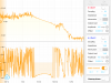
I compared the OLTF of PLLY measured on 2/15 with the calculat model.
The transfer function model takes into account the the servo filter, PFD, actuator efficiency, and the resonance of the laser PZT and time delay.
The resonance frequency of PZT was set to 300 kHz, and the Q factor was set to 20.
The time delay term is exp (-i * f * 10 ^ -5).
Also, although the second and third boost filters are 20 Hz / 2 kHz, they are set to 20 Hz / 1.6 KHz for to match the measured values.
I compared the OLTF of PLLY measured on 2/15 with the calculat model.
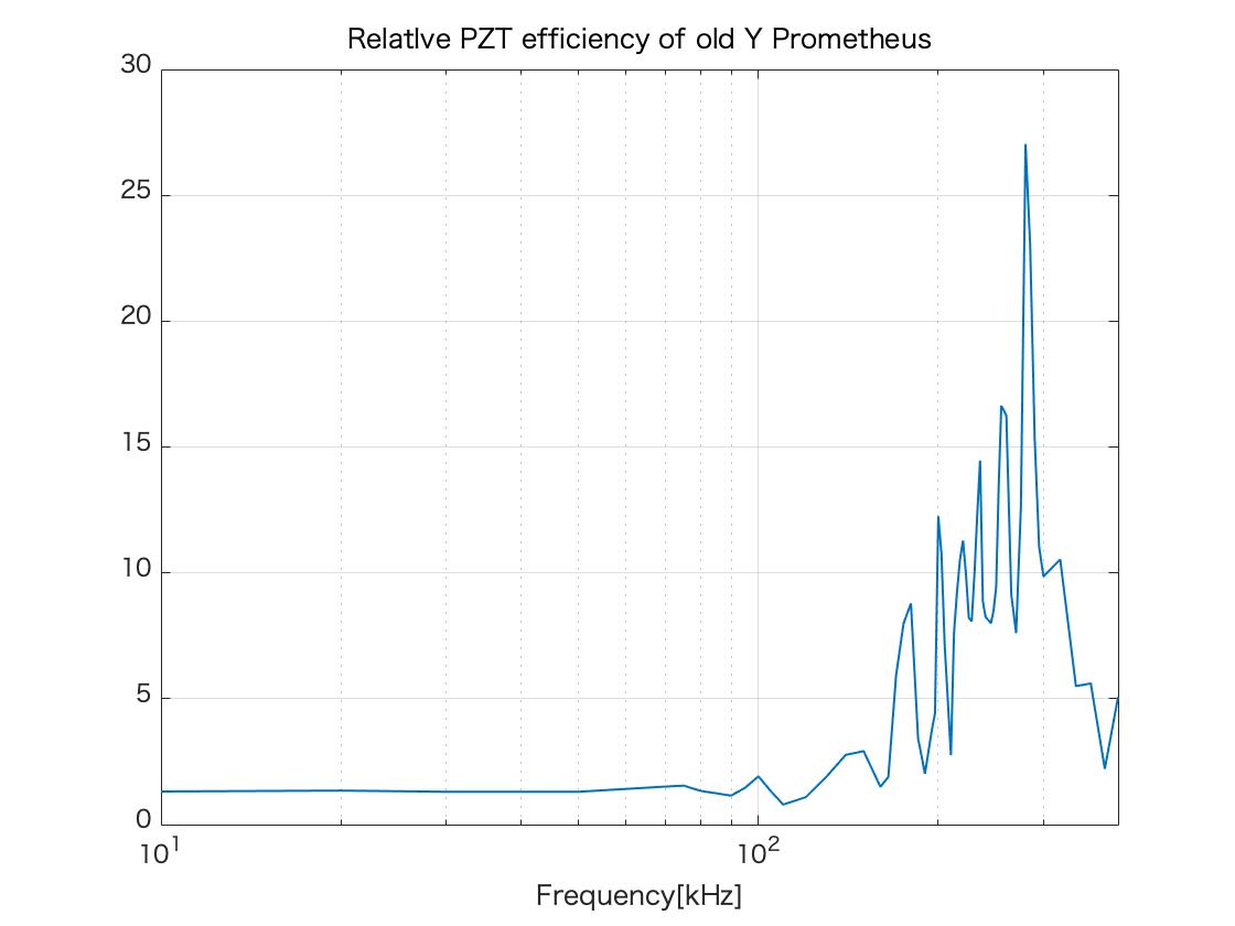
The transfer function model takes into account the the servo filter, PFD, actuator efficiency, and the resonance of the laser PZT and time delay.
The resonance frequency of PZT assumed to 300 kHz, and the Q factor set to 20.
The time delay term set to exp (-i * f * 10 ^ -5).
Also, although the second and third boost filters are 20 Hz / 2 kHz, they are set to 20 Hz / 1.6 KHz for to match the measured values.
The transfer function model takes into account the the servo filter, PFD, actuator efficiency, and the resonance of the laser PZT and time delay.
The resonance frequency of PZT assumed to 300 kHz, and the Q factor was set to 20.
The time delay term is exp (-i * f * 10 ^ -5).
Also, although the second and third boost filters are 20 Hz / 2 kHz, they are set to 20 Hz / 1.6 KHz for to match the measured values.

