On 11 and 12 Mar 2019.
Simon, Yano, Akutsu
We have completed the WAB finalization at Xend. This is the last WAB to be finalized.
On 11th
Preparation
As usual (see 8214, 8223), we needed to move two clamps fixing the security frame for the cryopayload close to the WAB base plate before traversing the WAB back into the nominal position from its saving mode location. This time, we found another issue on the breadboard: there was a burndy connector unit where the clamps for WAB base plate would come; so we moved it carefully. It seemed somewhat tensioned already before we touched, so we needed to pay attention as much as possible so that our work won't cut the wires... hopefully that would not happen.
Finalization of the WAB
- Detached the flange protectors that were attached at the front edge of the WAB.
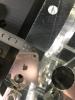
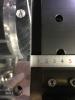
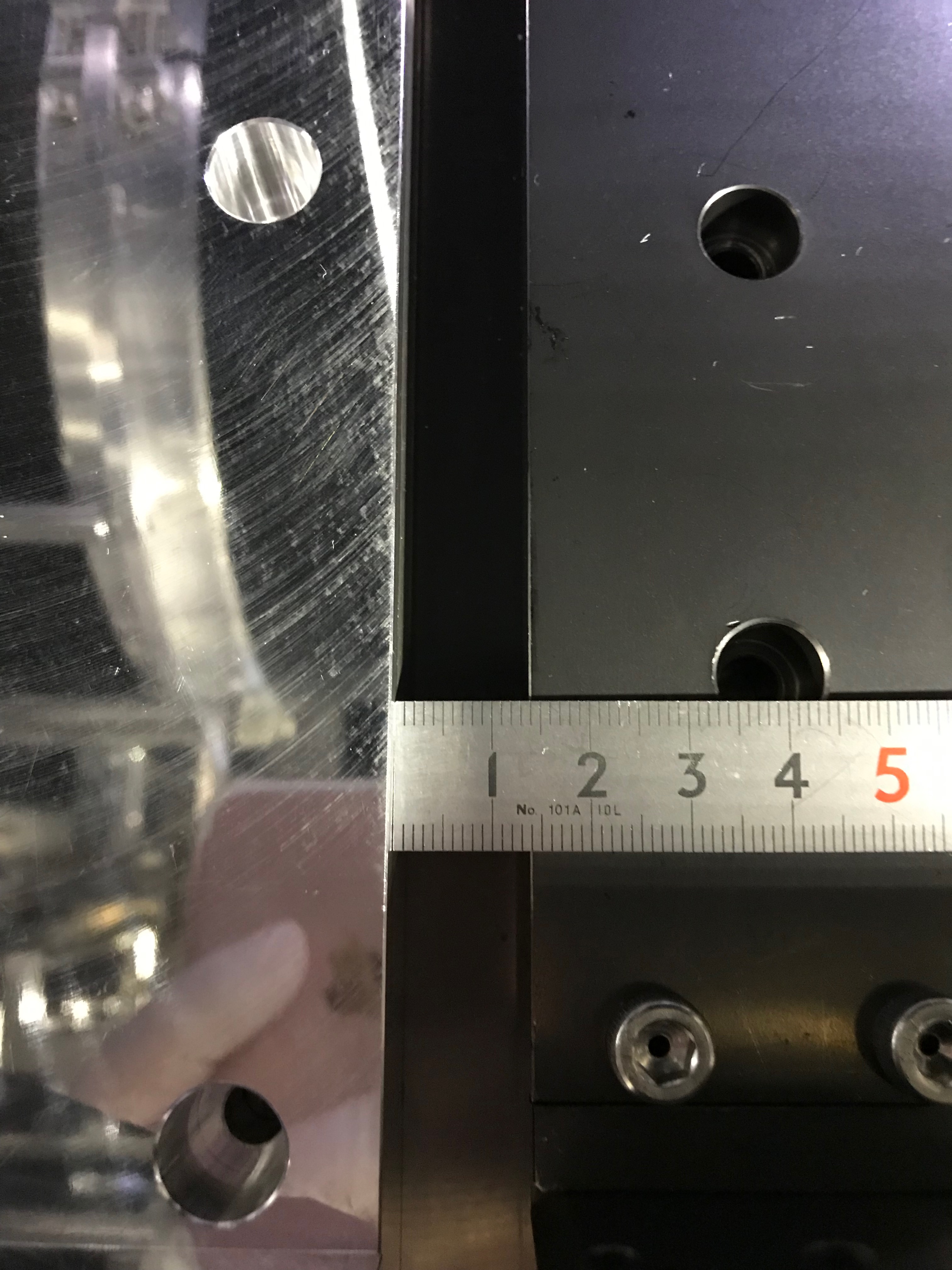
- Set up the WAB traverser, and lifted up the WAB suspension, and transported it to the nominal position. To fix the base plate to the breadboard, we could not use the originally planned M6 narrow-cap screws but 12pcs clamps, as it turned out that the gap between the WAB and the recoil mass of the cryopayload would become too small if we would adopt the original plan; finally the gap should become around 10mm (+alpha). See also JGW-G1808538, where at IXC we made the gap as 22mm but here 10mm (Fig 1 and 2).
- When we set the traverser's beams on the structure of the inner shield, where some electric wires were laying and unfortunately interfered against the traverser, so we moved them by cutting the cable ties.
- As we were worried about the VIS work that they were doing over us would affect the WAB's final position (depending on the position of the cryopayload, the WAB needs to be moved again??), so we just left the setup of the traverser this day.
- Then I attached pins to the two thermometers that will be installed here...
On 12th
- After discussing with VIS folks, we determined to detach the WAB traverser setup, assuming that the WAB should not be moved.
- Along with that, we attached the following small items as usual.
As follows!
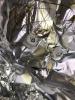
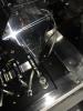
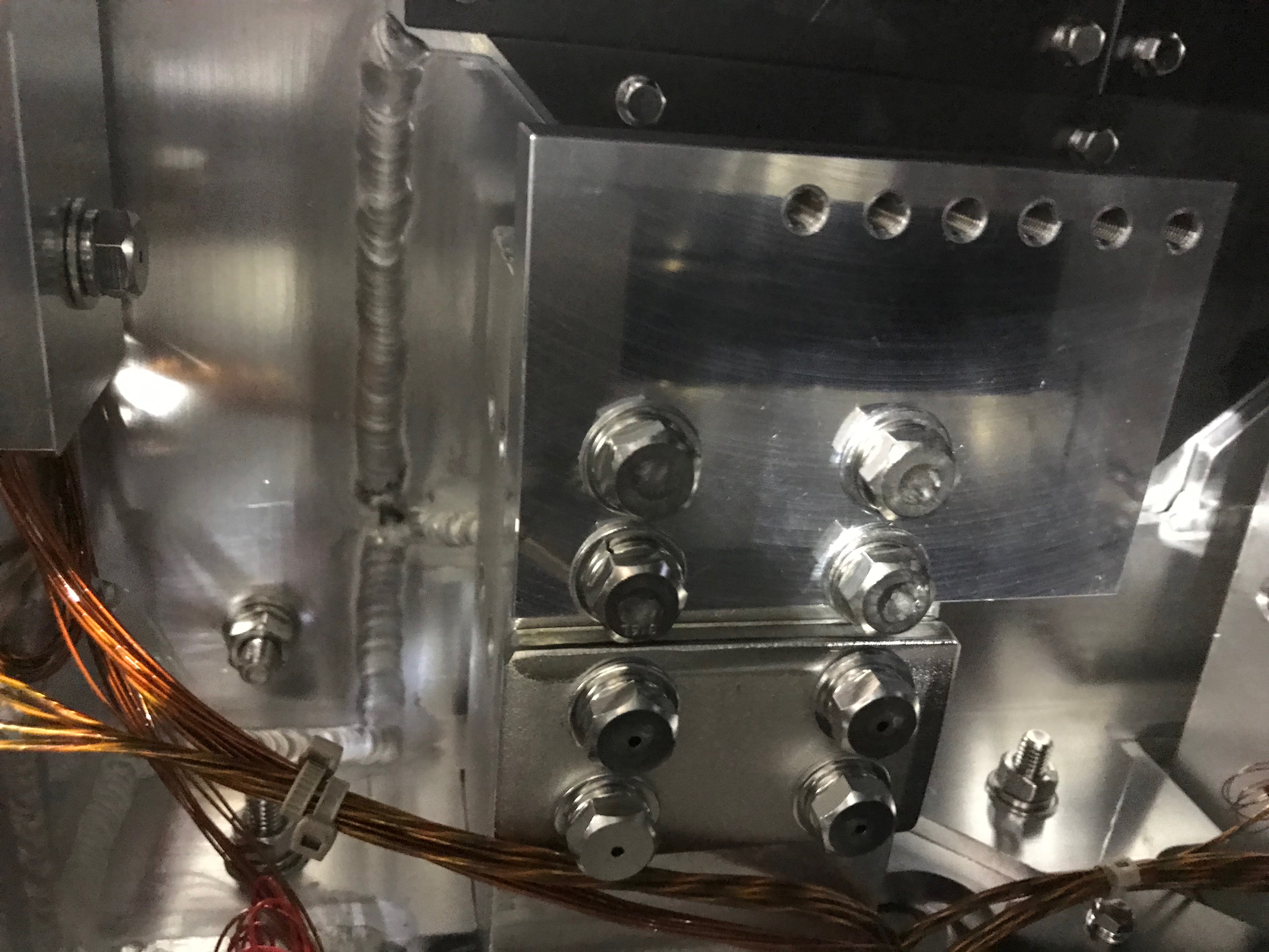
- Adapter block to the cooler head: an adapter block, which will interface four 6N Al heat links from the WAB and the cooler head, was attached to the cooler head (Fig 4). Four M8-40 screws, the plain washers, and the spring washers will be used, and the final torque of 15Nm (5-> 10-> 15) will be applied to each by a torque wrench, but today we forgot some plain washers so they were partly done.
- 6N Al heat links: four 6N Al heat links were connected to the adapter block and the dual flanges of the WAB. Four M5-10 screws, the plain washers, and the spring washers were used to fix the tags of the heat links to the WAB flanges, and the final torque of 5Nm was applied to each by a torque wrench. In the same manner, four M5-10 screws, the plain washers, and the spring washers were used to fix the tags of the heat links to the adapter block, and the final torque of 5Nm was applied to each by a torque wrench. When I fixed the tags to the adapter block, the tags tended to rotate during screwing, so we somehow stop them rotating as much as possible.
- Flange tag for a thermometer: a tag for a thermometer for one of the WAB flange was also attached. An M5-10 screw, the plain washer, and the spring washer were used. The torque was 5Nm as well.
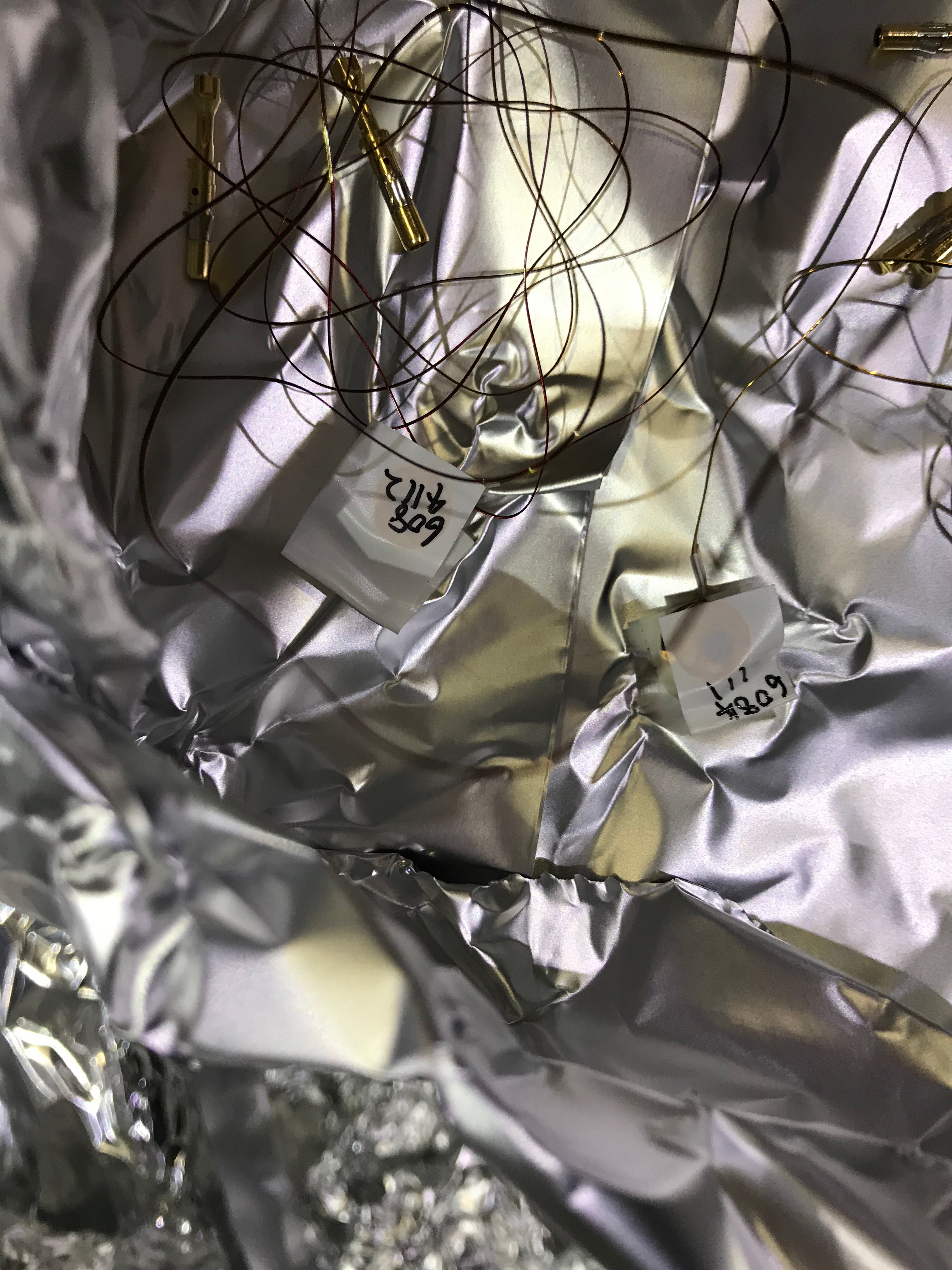
- Thermometers: two thermometers (LakeShore DT-670B-CU) were attached to the WAB and the suspension structure; one (S/N#6084111) was attached to the WAB itself, while another one (S/N#6084112) was attached to the suspension structure. For each thermometer, a M3-10 screw, the washer, and the spring washer was used to fix without using the torque wrench.
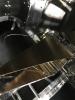
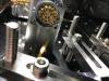
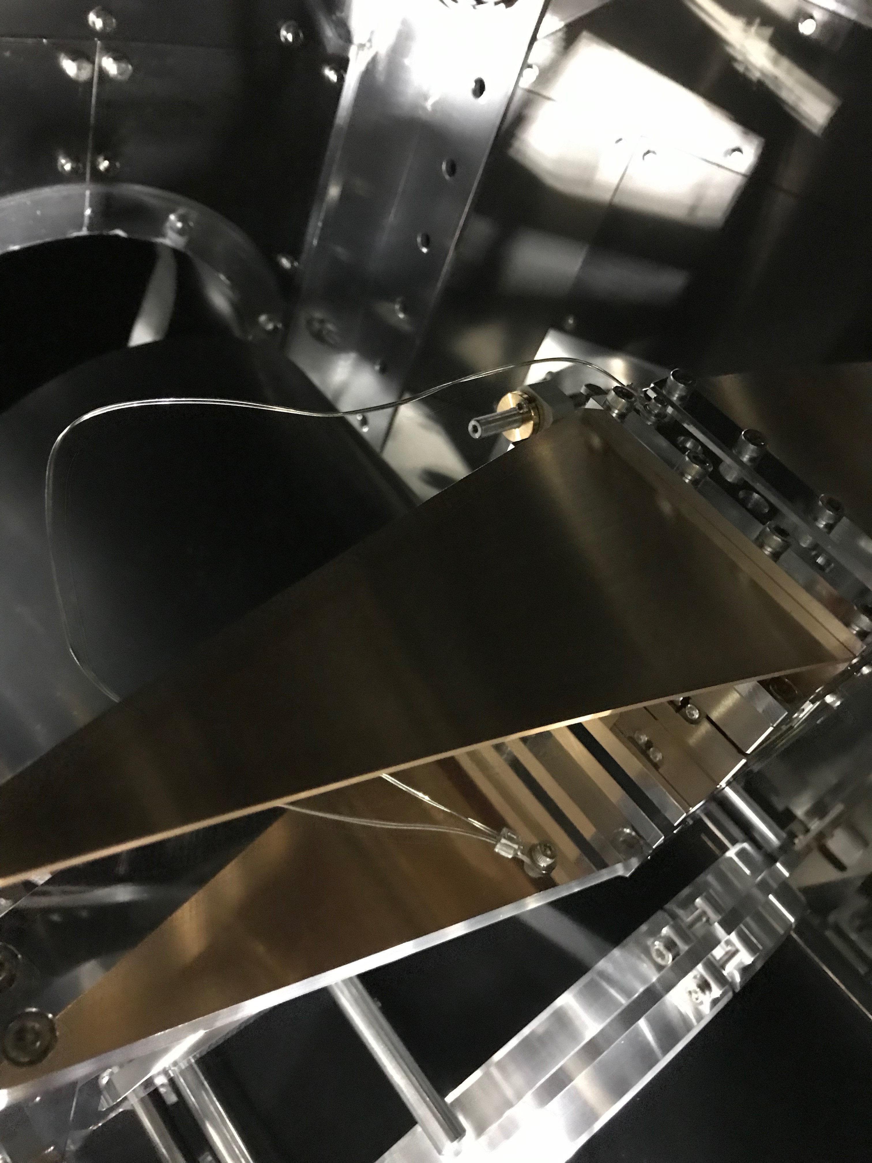
- Easy heat link: an easy heat link, which Yano-san assembled in the last time, was attached. It was attached to the WAB suspension to connect the upper and the lower part with two M3-8 screws, the flat washers, and the spring washers (Fig 5).
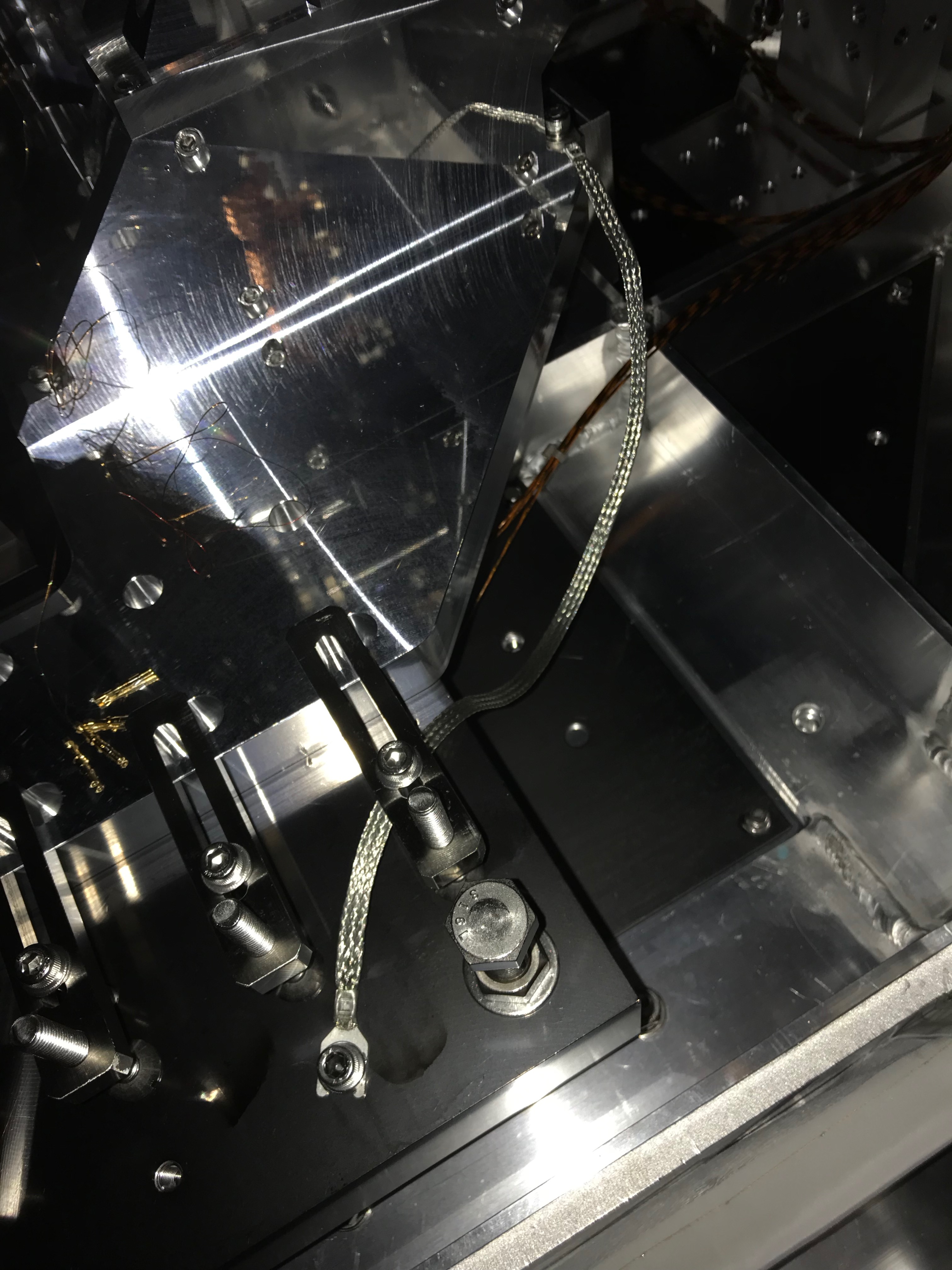
- Mid heat link: as was done at IXC, we attached a mid heat link to connect the WAB suspension structure and the breadboard hopefully-thermally (Fig 6). The background story of this linkage is that we cannot use originally planned M6 screws to fix the WAB base plate to the breadboard, so we are worried about the thermal contact of the base plate to the breadboard, so we determined to attach the mid heat link.
- Support blocks: as the base plate was shifted to the arm side, the support block without additional machining could be used to support the backside of the base plate.
- Then connected electric wires of the thermometers: used P23 burndy connector as usual, and the pin assign is:
The assignment is
- ABCD: V-, V+, A-, A+ in this order, and the pins are from the WAB itself
- EFGH: V-, V+, A-, A+ in this order, and the pins are from the suspension structure
and checked the diode's directions at the edge of the cable outside.
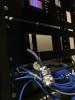
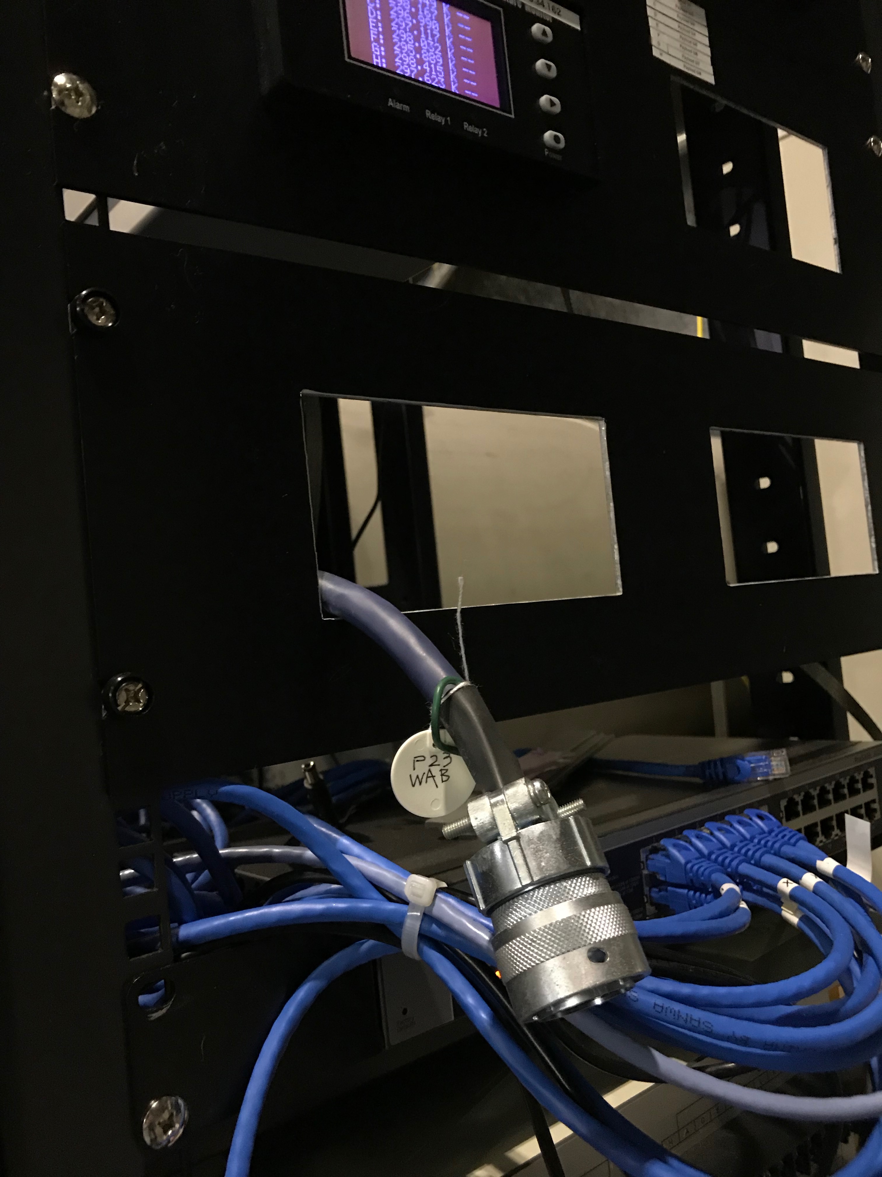
Fig 7 shows the burndy cable from the P23 connector of the EYC chamber; I today attached the white circular tag to indicate it is coming from P23.
There were two issues about the burndy connector.
(1) P23 was already occupied by the illuminator; Yokozawa-san kindly finally took care of the replacement to P29. The cables from those connectors were also somehow managed again...
(2) The pin arrangement at P23 inside the 8K shield was wrong. If the word "wrong" is inappropriate, the pin arrangement was rotated about 1pin when you compare it with that of the connector attached at the just outside of the chamber. Anyway, we determined to use the pin arrangement outside the chamber as the reference, and connecting pins from thermometers in the 8K shield in the order (Fig 8).
