= Geophones calibration=
Assuming that the IP LVDT driving and sensing calibration is correct I used it to intercalibrate the IP geophones.
We follow the same procedure used for the accelerometers on ETMX IP ( see entry 7341 ).
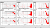
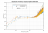
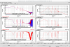
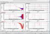
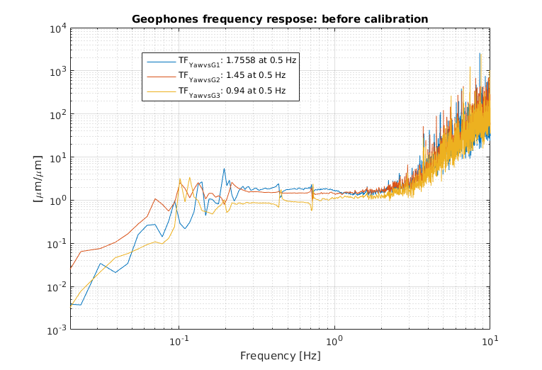
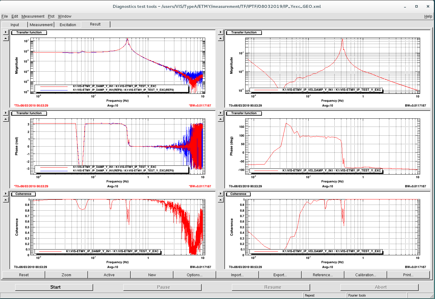
I injected noise in Yaw and measured the ratio between LVDT yaw and each geophone response (converted in diplacement): (Yaw_LVDT*r)/(GEO)/(w)
Such function (shown on pic1 and pic2) should be flat in the region from 200 mHz to ~2 Hz (where the coherence is 1).
The extrapolated calibration factors are:
| cal G1 at 0.5 Hz | 1.7578 |
| cal G2 at 0.5 Hz | 1.45 |
| cal G3 at 0.5 Hz | 0.94 |
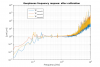
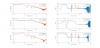
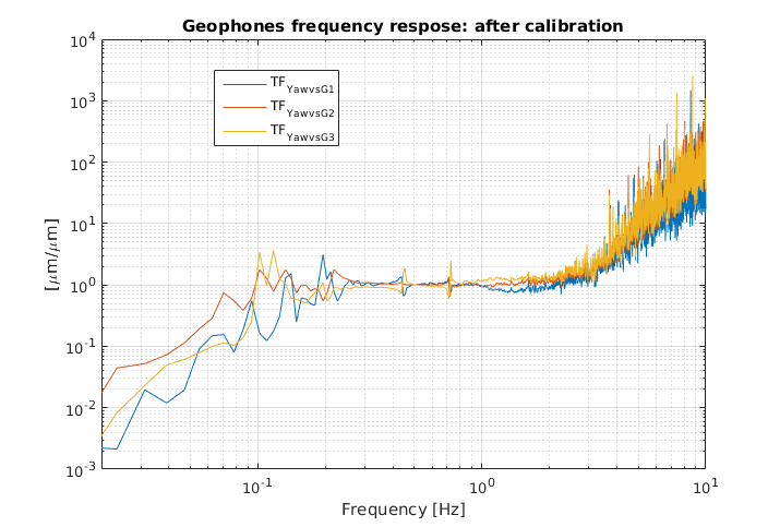
As expected, after implementing the calibration the fuction is one in the flat region (pic 3).
=Geophones sensing matrix=
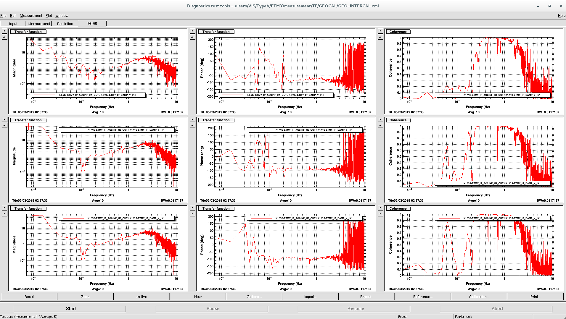
Then I have computed the diagoanlized sensing matrix by injecting a line at 2 Hz for each d.o.f and measuring the amplitude and phase of the TF between each GEO (converted in displacement) and the diagonalized LVDT sensor.
TF_ji = (GEO_j/(2pi*f0))/LVDT_i j = 1, 2, 3 i = L, T, Y f0 = 2 Hz.
This values are reported in a matrix where the columns correspond to L, T and Y and the lines to the three geophones.
The sensing matrix, is computed as the inverse of such matrix, and it is reported below:
| H1 | H2 | H3 | |
| 0.6022 | -0.1876 | -0.3948 | GEO_L |
| 0.0957 | -0.6754 | 0.6508 | GEO_T |
| 0.5605 | 0.6721 | 0.6846 |
GEO_Y |
Now the calibration factors and Geo sensing matrix are implemented in the MEDM screen.
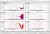
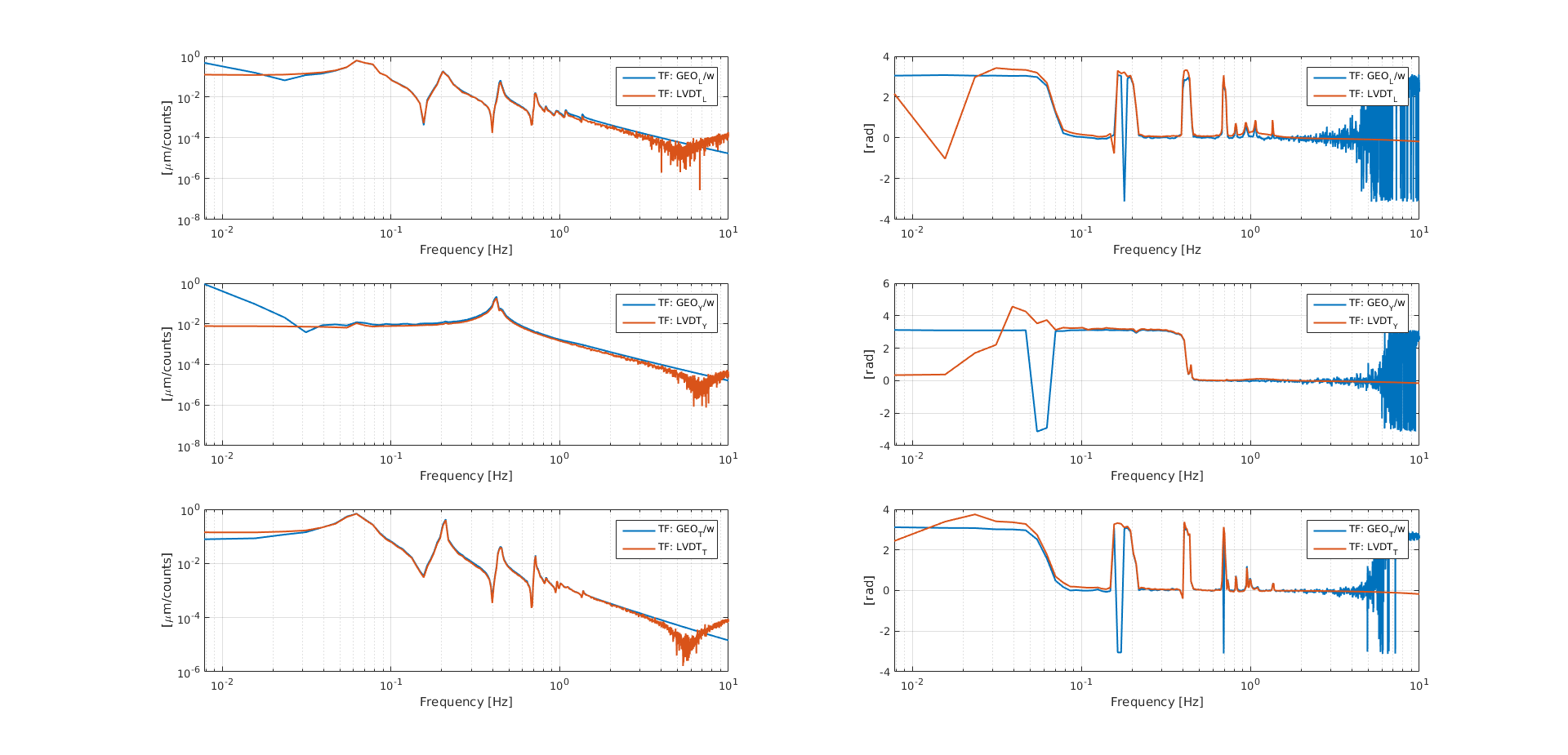
As a final check I have to measure the TF injeecting noise from the diagonalized virtual acutators and looking at the diagonalized LVDT and geophones and verify that: TF_LVDT = TF_GEO/w.