K. Nagano, Akutsu on Oct 6 2018
Have installed the subsequent optics following the BRT.
Preparation
The last time we had just left some dummy or ballast masses unfixed, the legs of the BRT unfixed, and so on unfixed... So we started with fixing them. The fixing work was done without any mechanical restraints --- neither the hamper plate nor the shims but taking care of the coil-yoke gaps by our eyeballs; even the restraints were not attached, the TMS-VIS's swinging was not so large, if you work carefully.
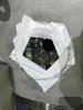
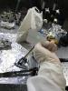
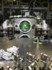
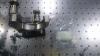
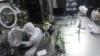
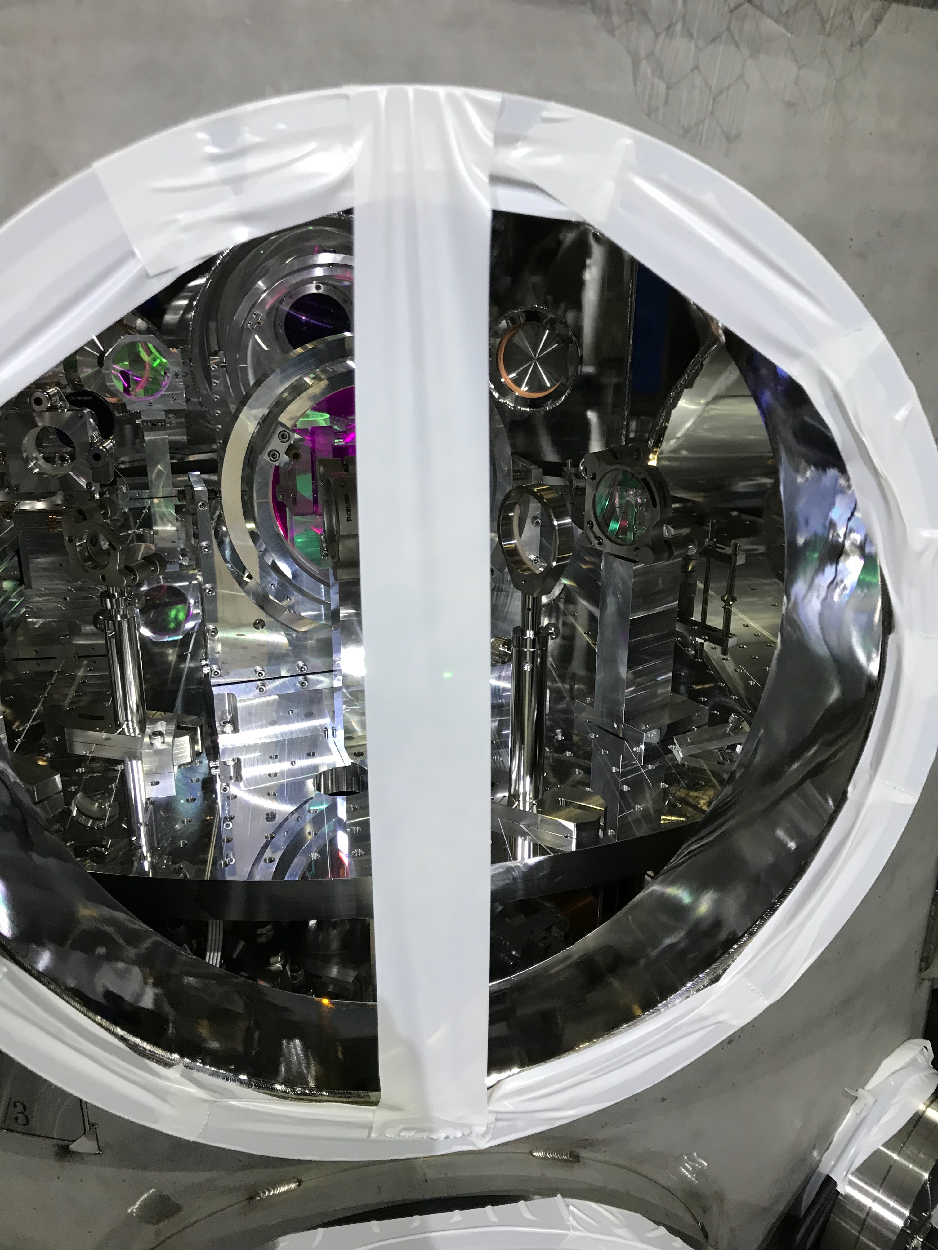
We opened one of the ICF152 flanges to be a window for oplev but this time it was for accessing inside the chamber. It was more useful than I expected!! (Fig 1)
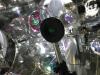
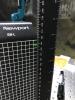
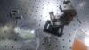
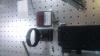
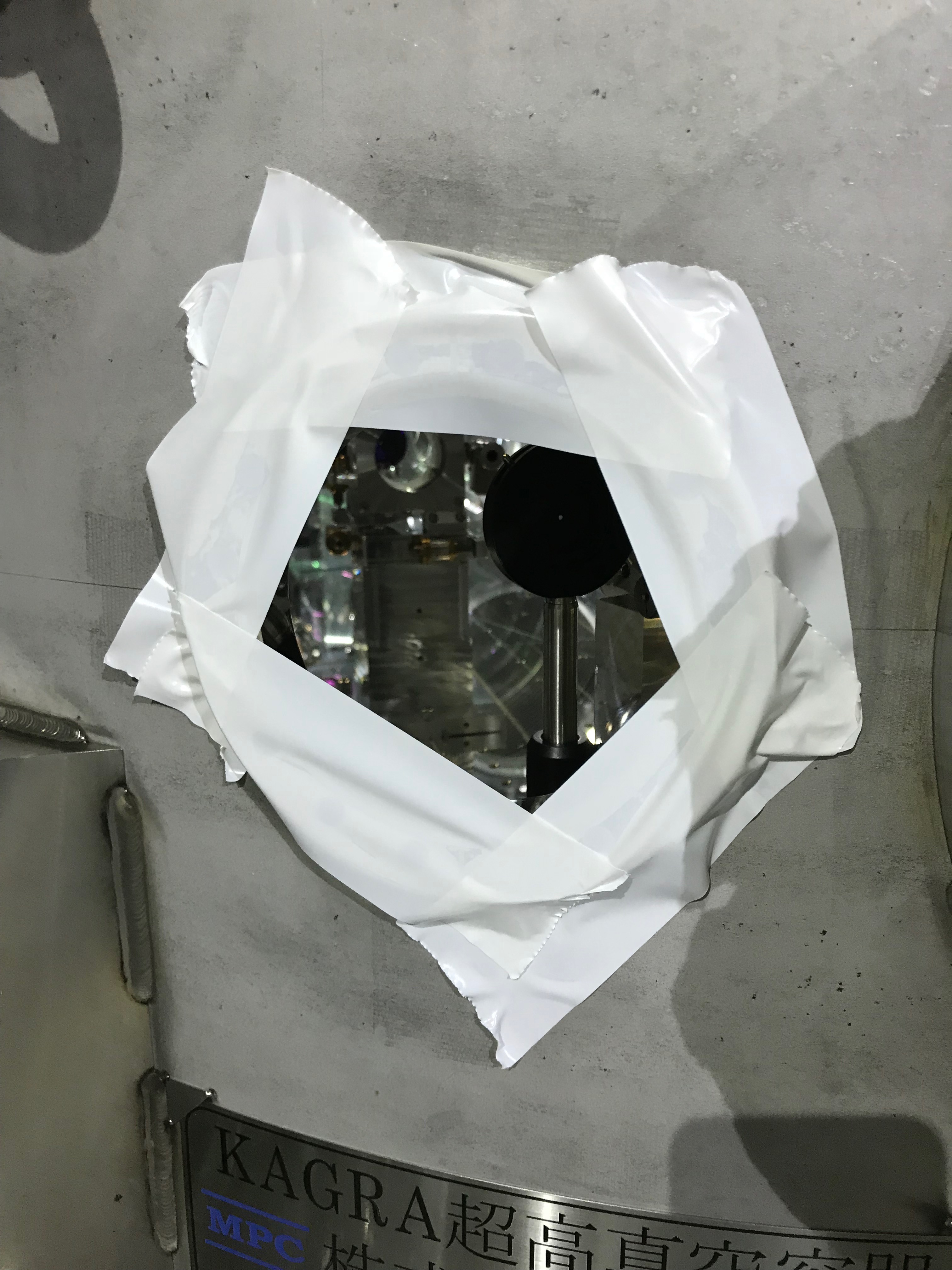
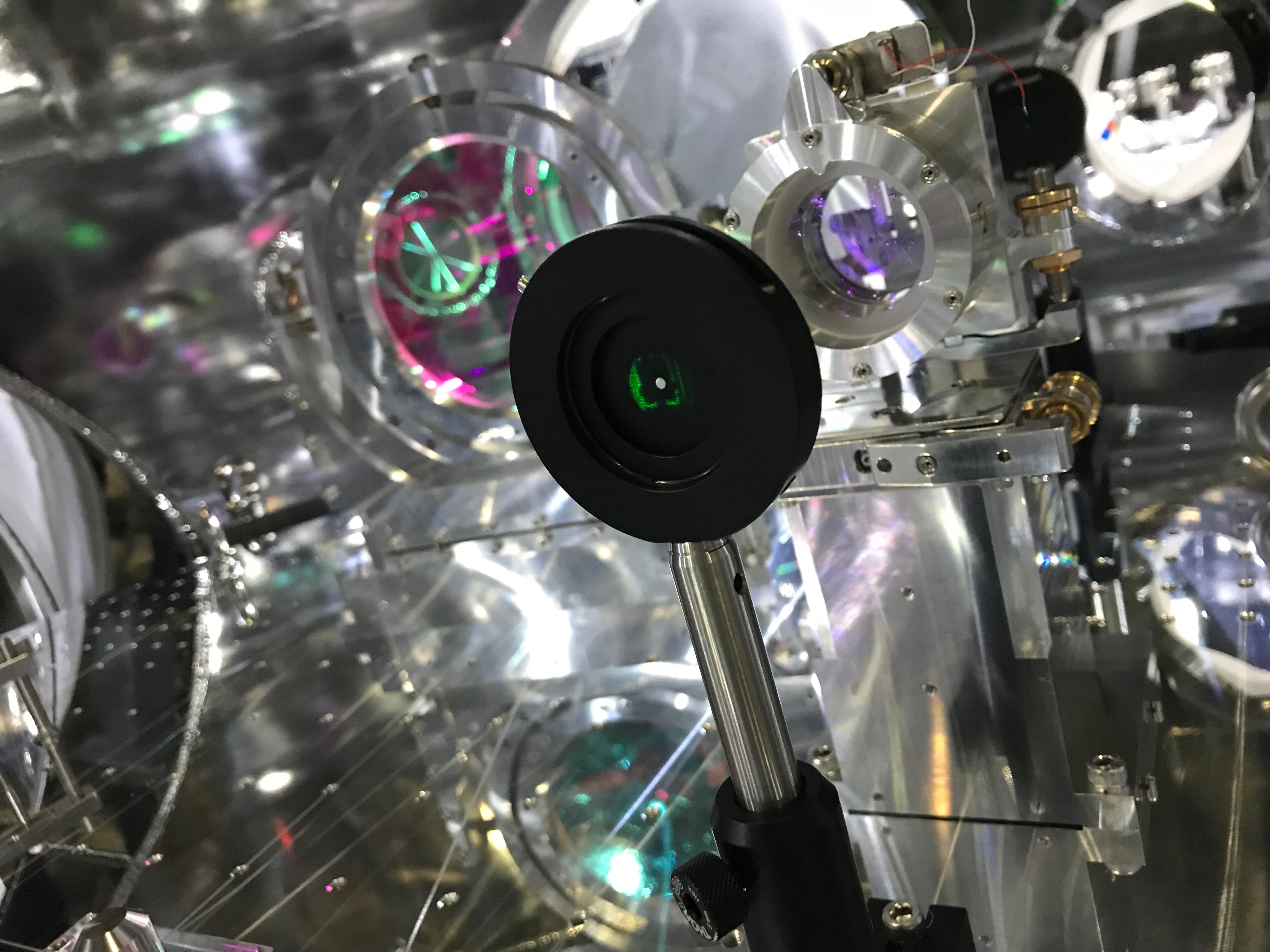
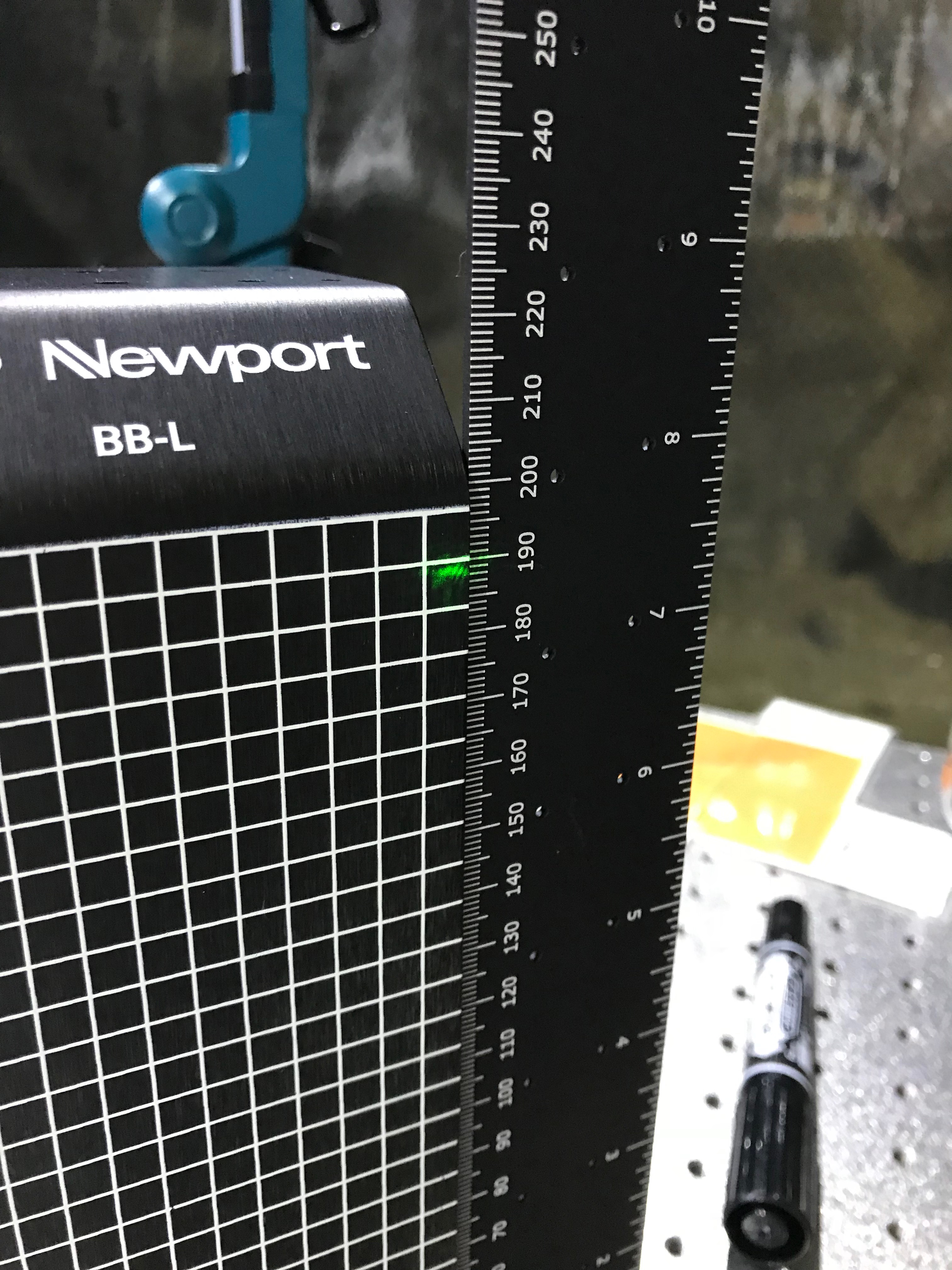
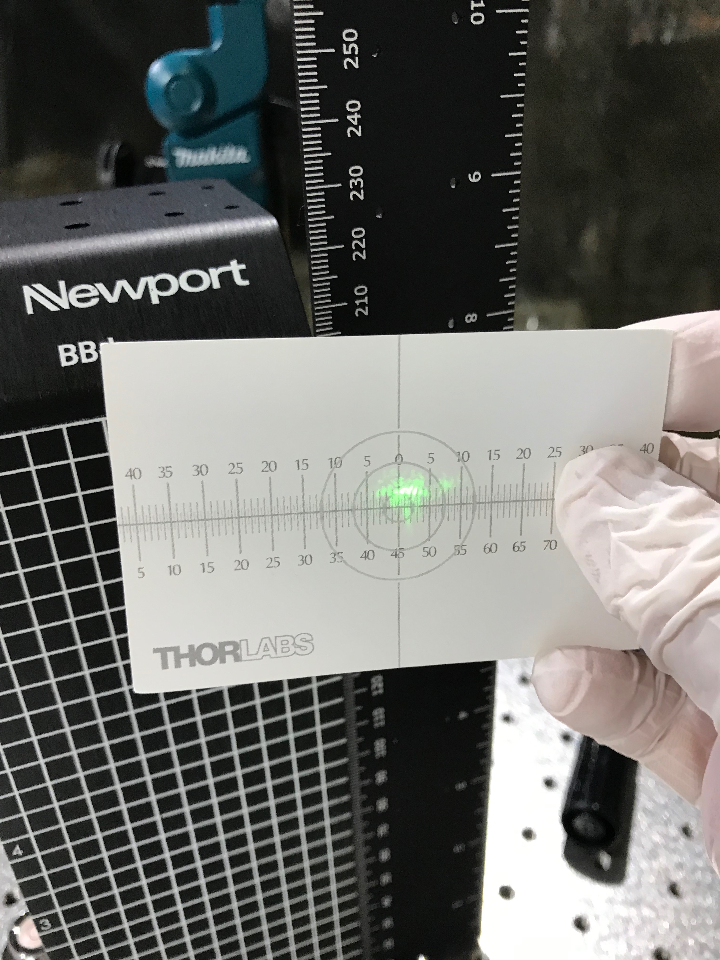
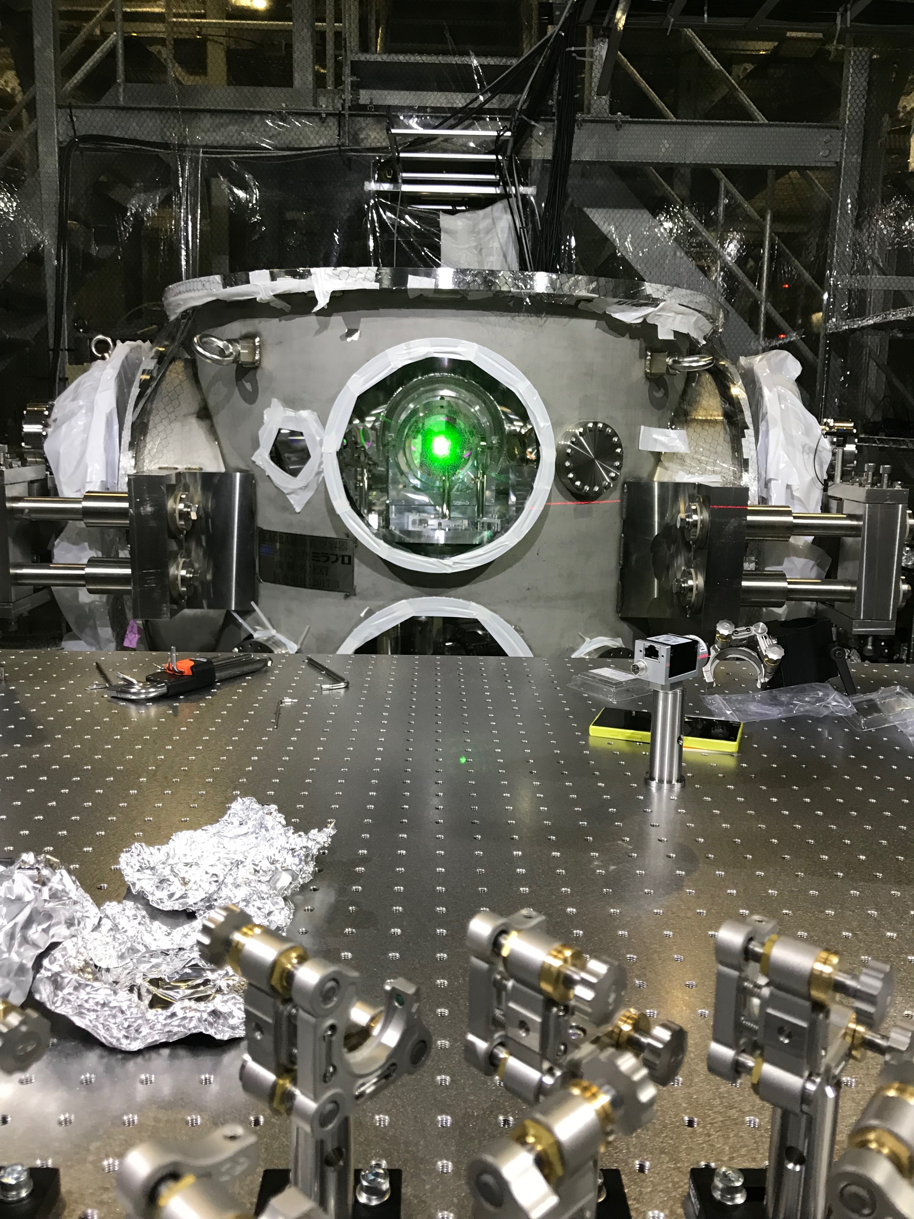
After fixing the all, we found we were so lucky  that the BRT seemed to be aligned to the green beam already. Just screwing down the bolts for the leg-supporters (the disks) seemd also change the balance (this time, in the better direction!) (Fig 2 and 3)
Steering mirrors and BRT3 lens inside the chamber
The following optics were set on the BRT base plate in the chamber.
- STM3: the third steering mirror just following the BRT2 lens: CVI HM-2037-45
- HBS: hermonic beam splitter (refl: IR, trans: GR): HBSY21
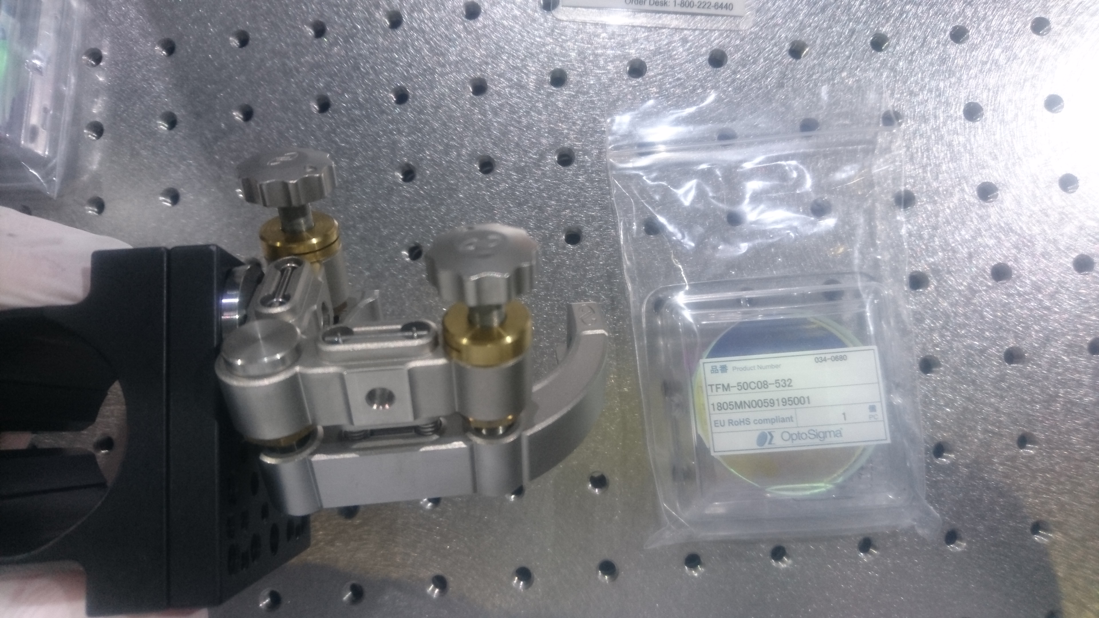
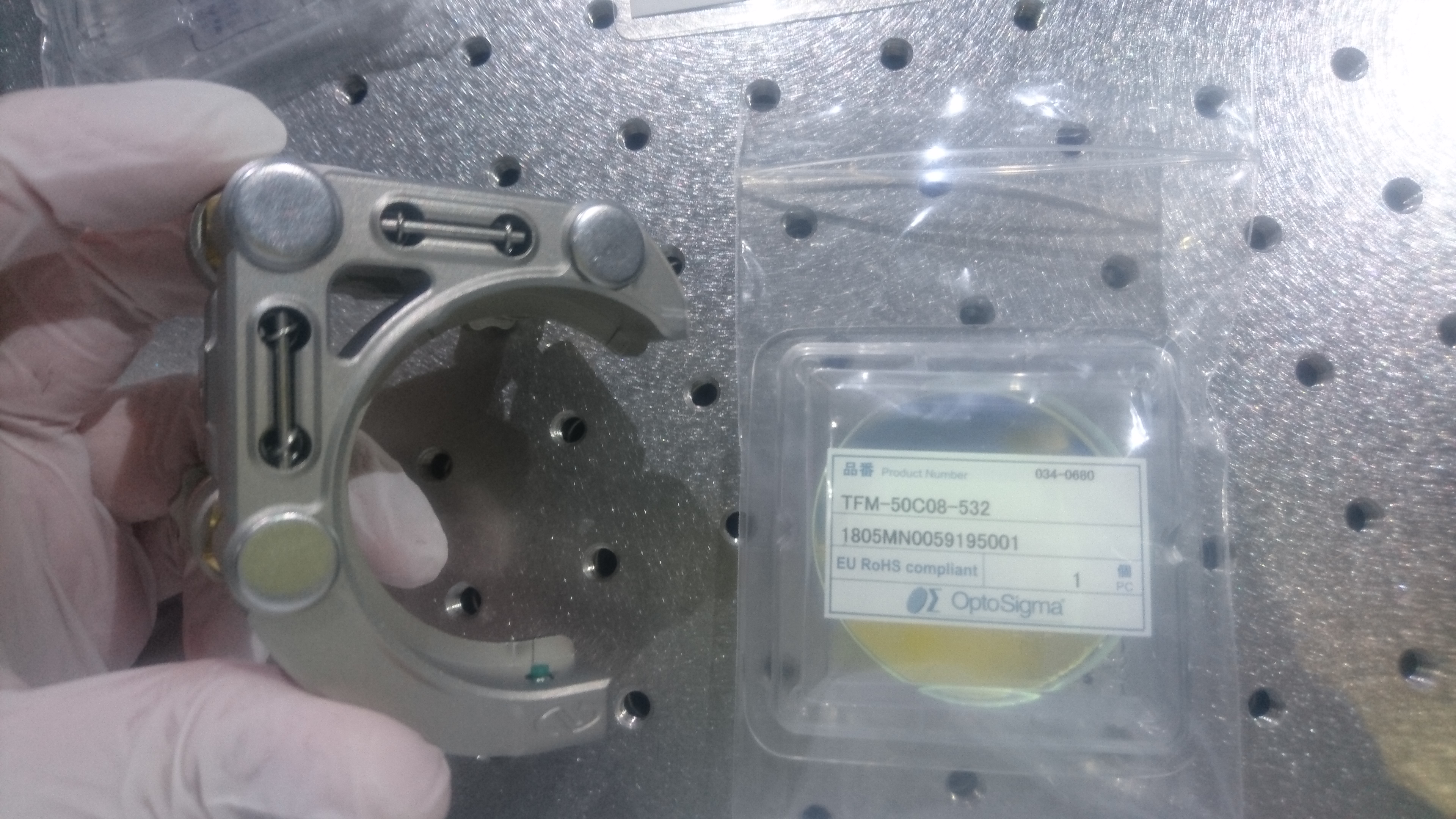
- BRT3: the third BRT lens only for green transmission from HBS: Sigma SLB-50.8-200NM
- GST0: green-only steering mirror following BRT3: Sigma TFMQSP-50.8C10-20-532/1064-0/26D
Actually their holders were already put at their rough positions for balancing the TMS-VIS. About the green beam, the optical path was aligned just using the green beam (most of the center part of the beam was hidden by the PD in EXA, though, and we hesitated to remove the PD; rather, we thought we could align our optics without removing it.). And thus the shadows could be seen in the mid of the beam (Fig 2 and 3).
For the oplev mirror on the BRT table, only the optical support was left... we did not insert the mirror on it today.
For IR beams, which we did not have still today, we just used a ghost beam reflection from HBS; this is the same method we did at TMSY in this April, but we did not (could not) confirm whether this method can align the IR or not; let's see!
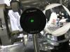
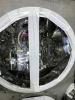
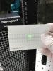
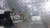
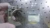
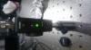
The green and the IR beams should be output from the center of the upper K400 flange finally, so their positions were important. We put a white tape tentatively and check their center-ish-iblity (Fig 4), and the tape was removed already. Without the BRT3 lens, the output image on the green beam was like shown in Fig 5. With the BRT3 lens, and tweaking some optics somehow, the beam was around the designed height (Fig 6), but the image was not so clean (Fig 7), but we thought it was sufficient at this level. Interestingly, to collimate the green beam, the position of the BRT3 should be before the GST0, while it should be after it in the Yend. Is this due to the difference of the beam profile of the green???
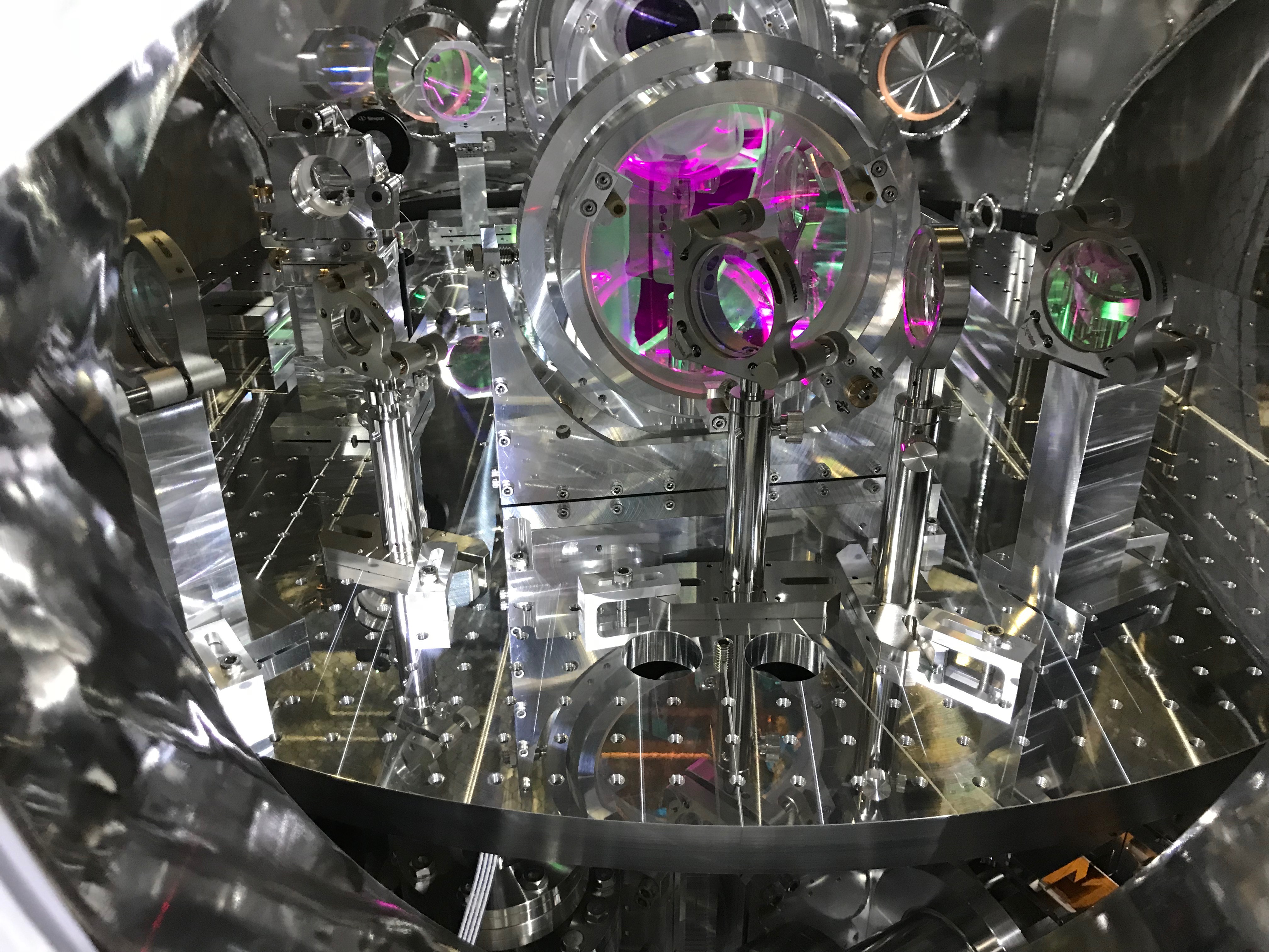
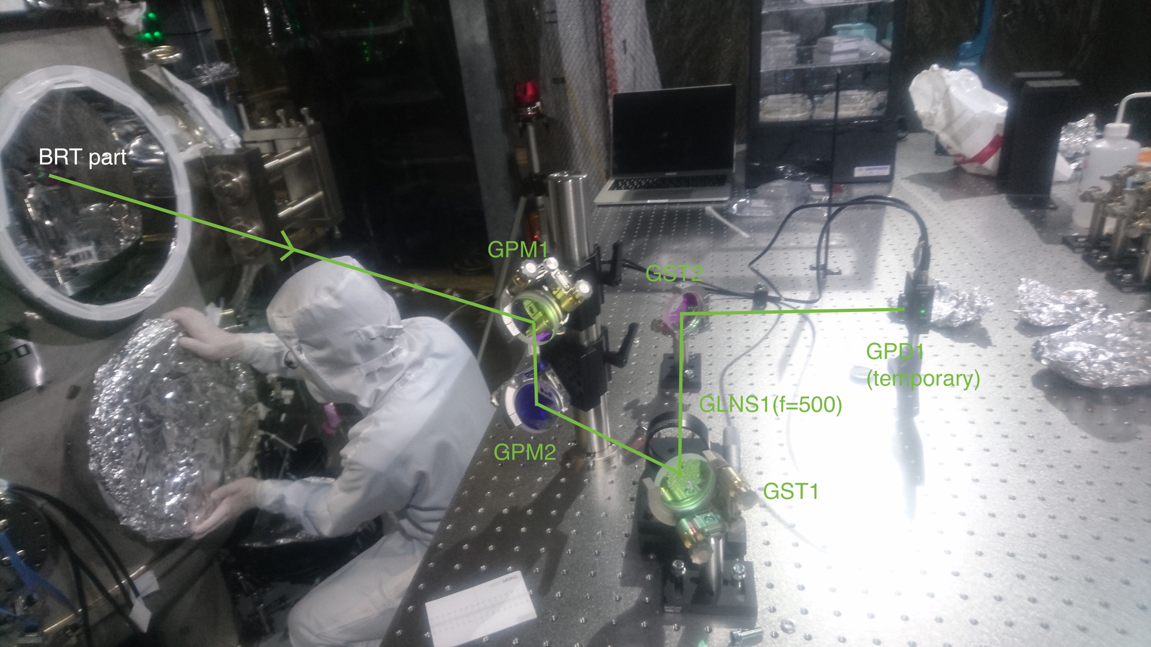
In the end, the installed subsequent optics was shown in Fig 8.
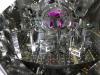
By the way, even the ghost green beam (used for aligning vertual IR beam path) was seen like in Fig 9... too shining?? Anyway we expect that the IR beam would follow this beam line when the IR light would resonate in the arm cavity in the (near?) future.
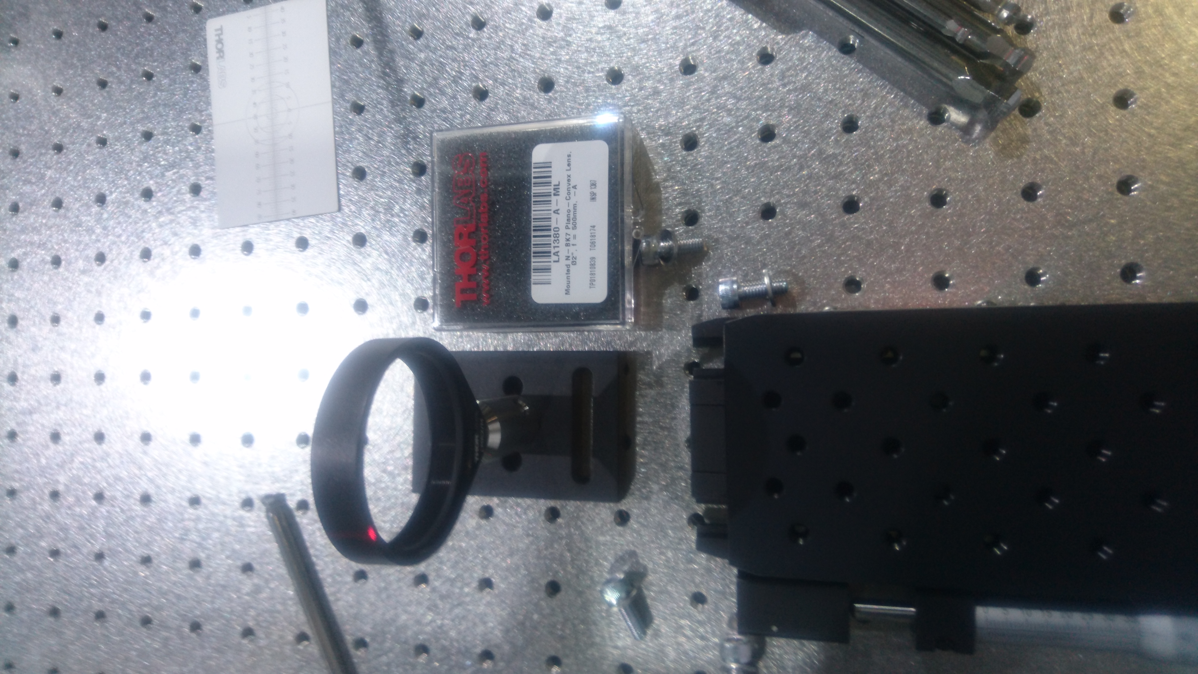
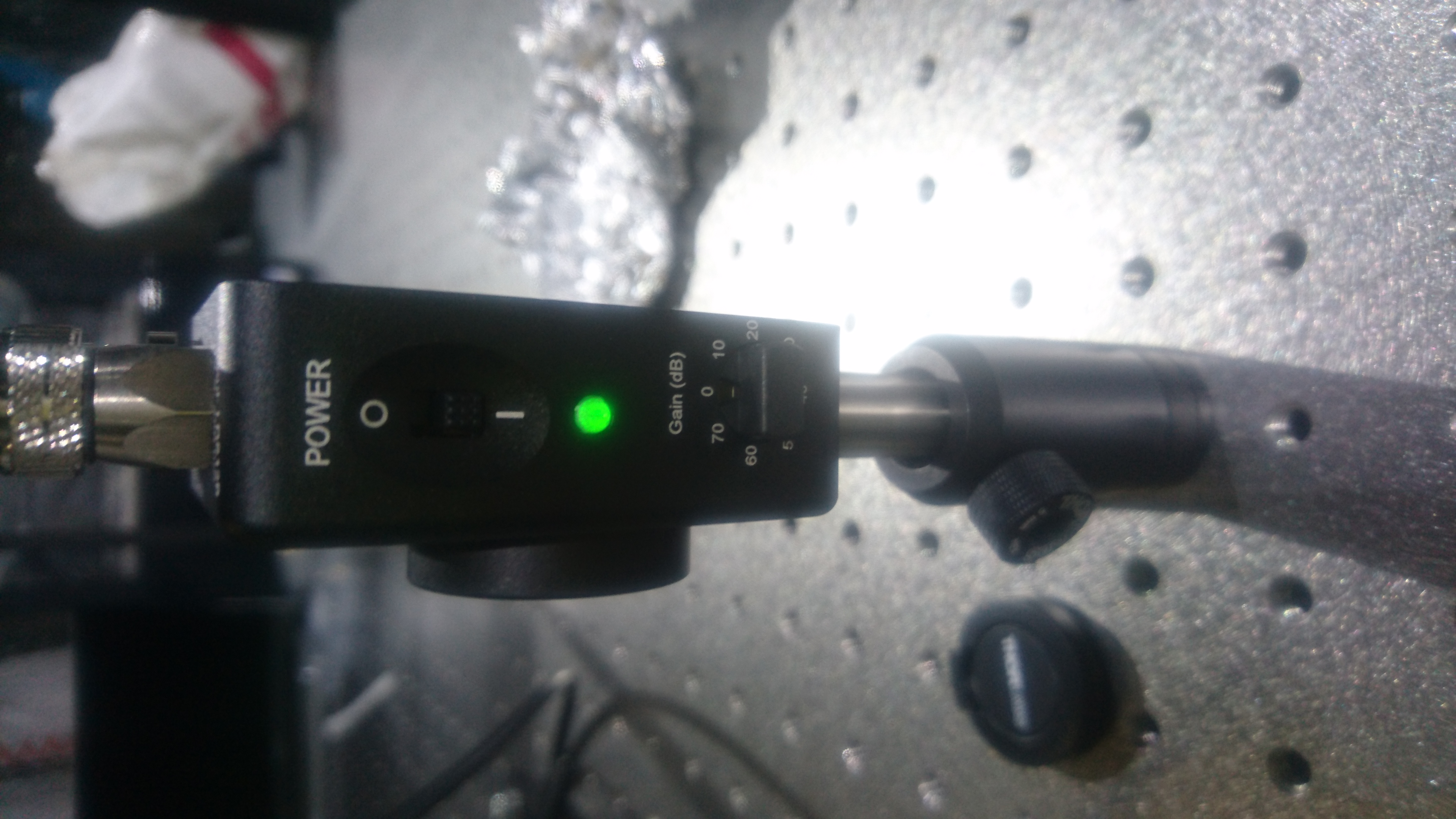
Optics outside the chamber
We have also put some optics on the optical table outside of the chamber and aligned the green beam into a DC-PD located tentatively according to the Nagano-kun's drawing. As already reported here, the PD has been already online!!!
Postscripts
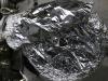
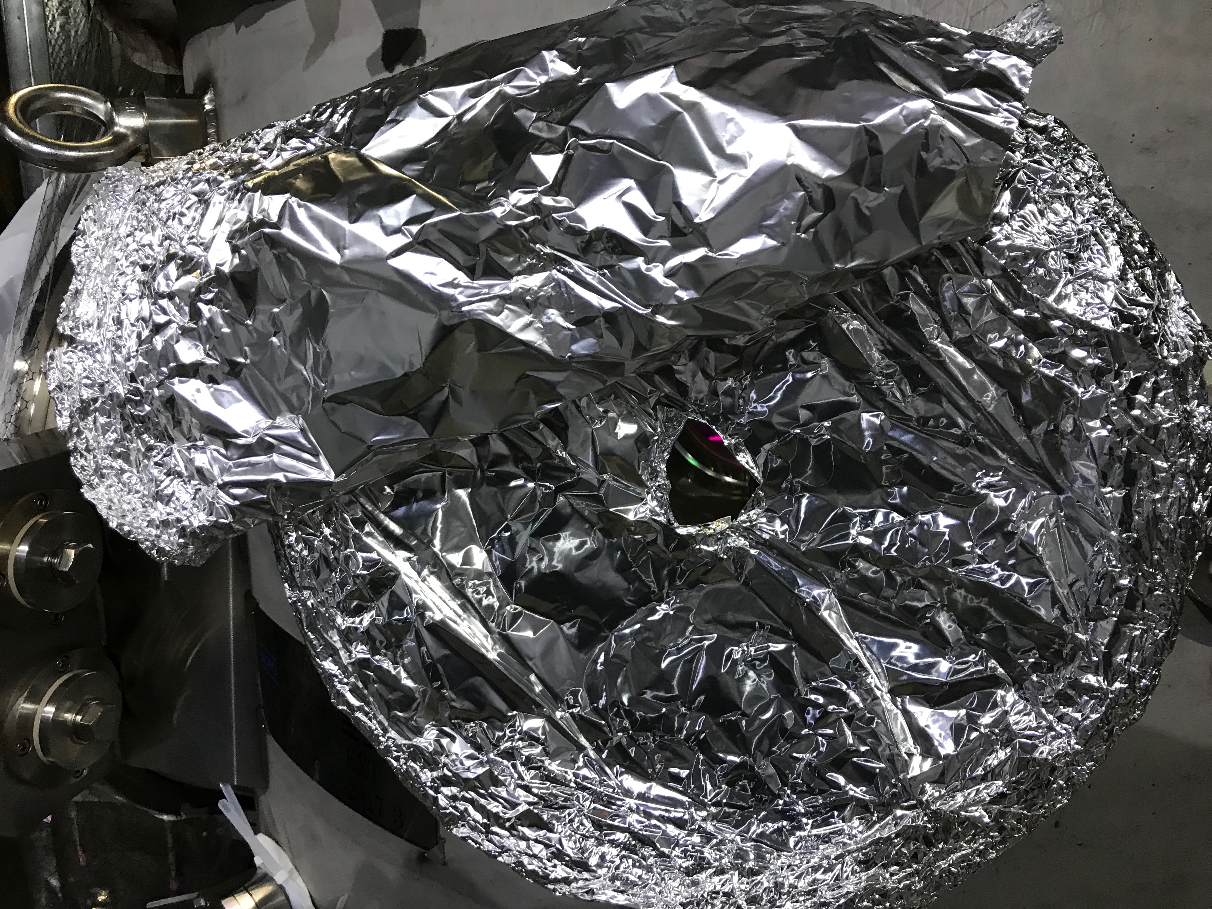
We put some aluminum foil with a hole for transmitting the beams (Fig 10).... And we found the train guys determined to stop Shinkansens from Toyama to Tokyo due to the typhoon No.25 (Kong-rey)'s approaching!
 .
. 