[Nakano, Nagano, Michimura]
IMC round trip length was measured to be 52.3 +/- 0.2 m from a mode scan (the design is 53.3m).
What we did
1. We have increased the output power from the PSL to 1 W with s-pol (high finesse). With ~500mW p-pol, we could barely see the MCe transmitted light with an IR card.
2. Aligned the optics on the IMC TRANS table. We have put a periscope, and a BS to split the beam into a camera and a DC PD (Thorlabs PDA100A). The gain of the PDA100A was set to be 40dB (with 70dB, it saturated, but for low finesse mode, 70dB is better).
3. Aligned the IMC.
4. Swept mode cleaner length by MCe (by sweeping K1:IMC-MCL_SERVO_EXC) to get mode scan data.
5. Get data with DTT (DQ channels somehow didn't work. The data was periodically lost.)
Analysis
1. Find the transmitted light (K1:IMC-MCL_TRANS_IN1) peaks and get the timestamps when there were peaks.
2. From the timestamps, derive the time it takes to sweep FSR (=t_FSR). This was done by the least squares fitting.
3. From the error signal (K1:IMC-MCL_L_OUT), get the timestamps when there were error signal from the sidebands.
4. From the intervals of the timestamp from the upper sidebands and the lower sidebands, derive the time it takes to sweep from TEM00 and one of the sidebands (=t_sb00).
5. The designed IMC roundtrip length is about 53.3 m, which correspond to the FSR of 5.6 MHz. The sideband frequency is set to be 52.72 MHz. Thus, 52.72 MHz correspond to 9*FSR + SB_00. So, calibration from the time to the laser frequency was done by 52.72 MHz/(9*t_FSR+t_sb00).
Results
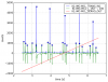
1. The time series data we have used is attached (modescantimeseries.png). The blue circles show the timestamps for the TEM00 and sidebands. It was a five-FSR scan.
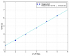
2. Got t_FSR = 0.74 +/- 0.02 from the fitting (fsrfit.png).
3. Got t_sb00 = 0.15 +/- 0.02 by taking the averages for 5 FSRs.
4. The FSR was calibrated to be 5.72 +/- 0.02 MHz. Which correspond to the roundtrip length of 52.3 +/- 0.2 m. The error here is the statistical error presumably from the motion of the mirrors.
The systematic error is not considered yet.
Next
- Find out the reason of the discrepancy between the measured and the designed.
- Fix DQ channels and do the scan with higher sampling frequency to measure the finesse.
- Misalign the optics and do the scan to measure the transverse mode spacing, and to derive the MCe RoC, and the incident angle to the MCe.
By the way, we swept MCe with 0.1 Hz triangle wave. We have also tried 0.3 Hz, 0.5 Hz, 2 Hz, but 0.1 Hz gave the most reliable scan.
The sampling frequency of the data acquired from DTT was 2048 Hz, which was not quite enough to measure the finesse.
The sideband frequency of the IMC was 51.72 MHz, not 52.72 MHz. So, the caribration was wrong.
The actual measured FSR is 5.62 +/- 0.02 MHz, and the roundtrip length is 53.4 +/- 0.2 m, which is consistent with the design.
Sorry we made a mistake!