Reports 1-1 of 1 Clear search Modify search
MIF (ITF Control)
yutaro.enomoto - 22:30 Monday 03 September 2018 (5991) Print this report
Initial Alignment Work: Day 1

[Kiwamu, Yuta, Eleonora, Satoshi, Taiki, Yutaro]

This is just a quick log for today's work. The details to be posted later.

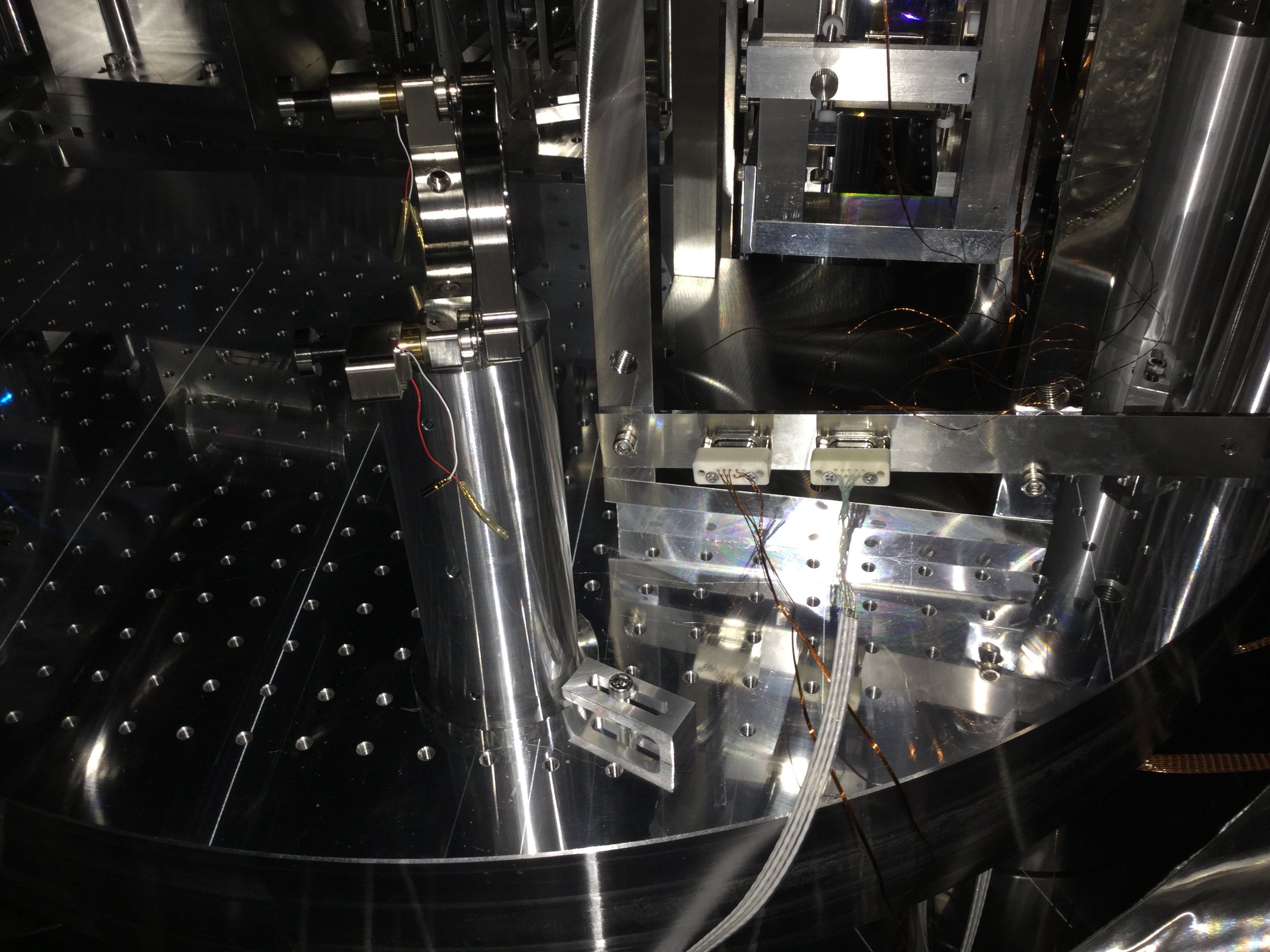
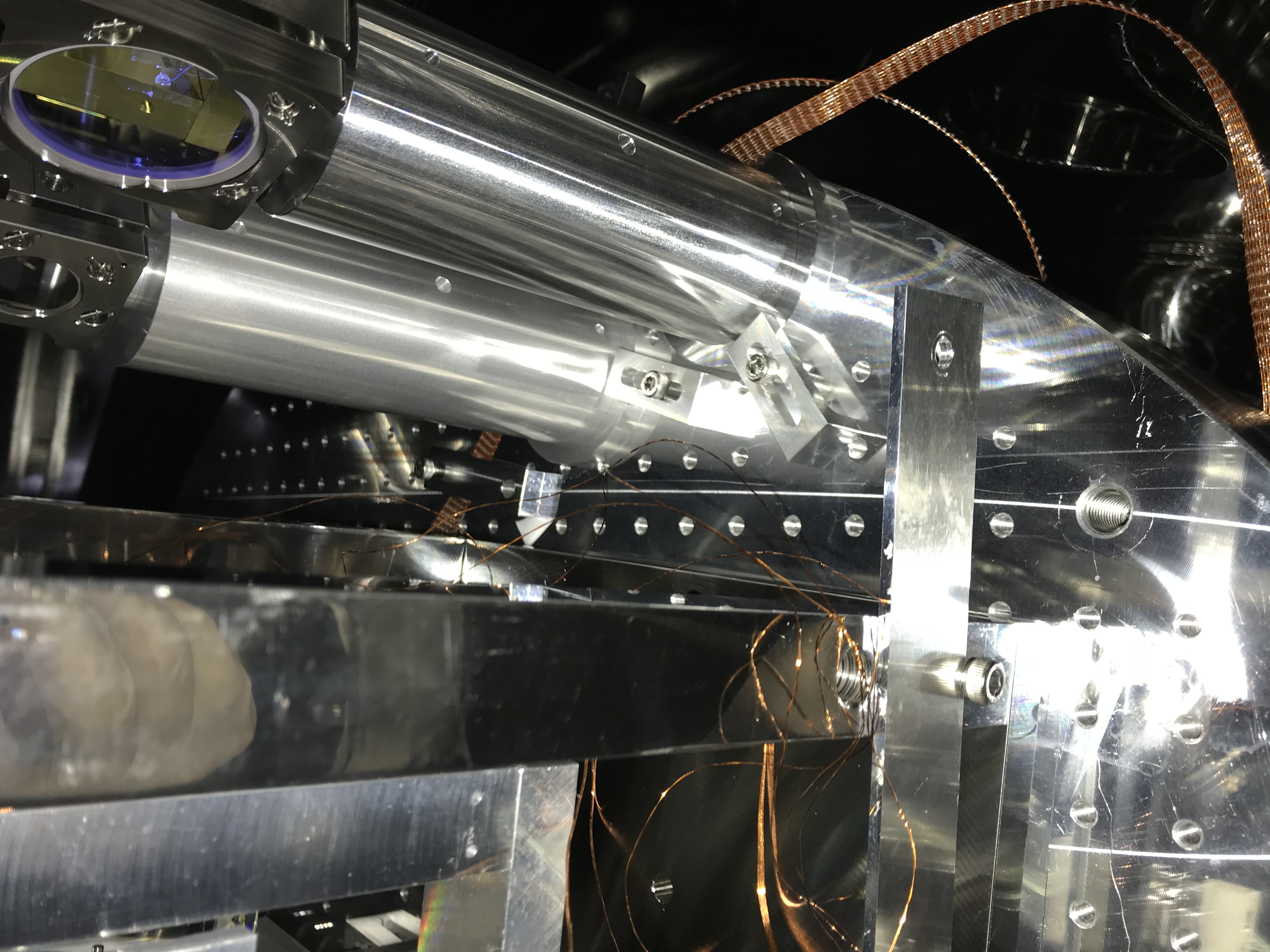
-- We moved IMMT1 suspension by ~ -2 cm in X direction, ~ -1 cm in Y direction, then aligned IMMT1 by pushers and pico so that the IR beam hits the center of IMMT2.
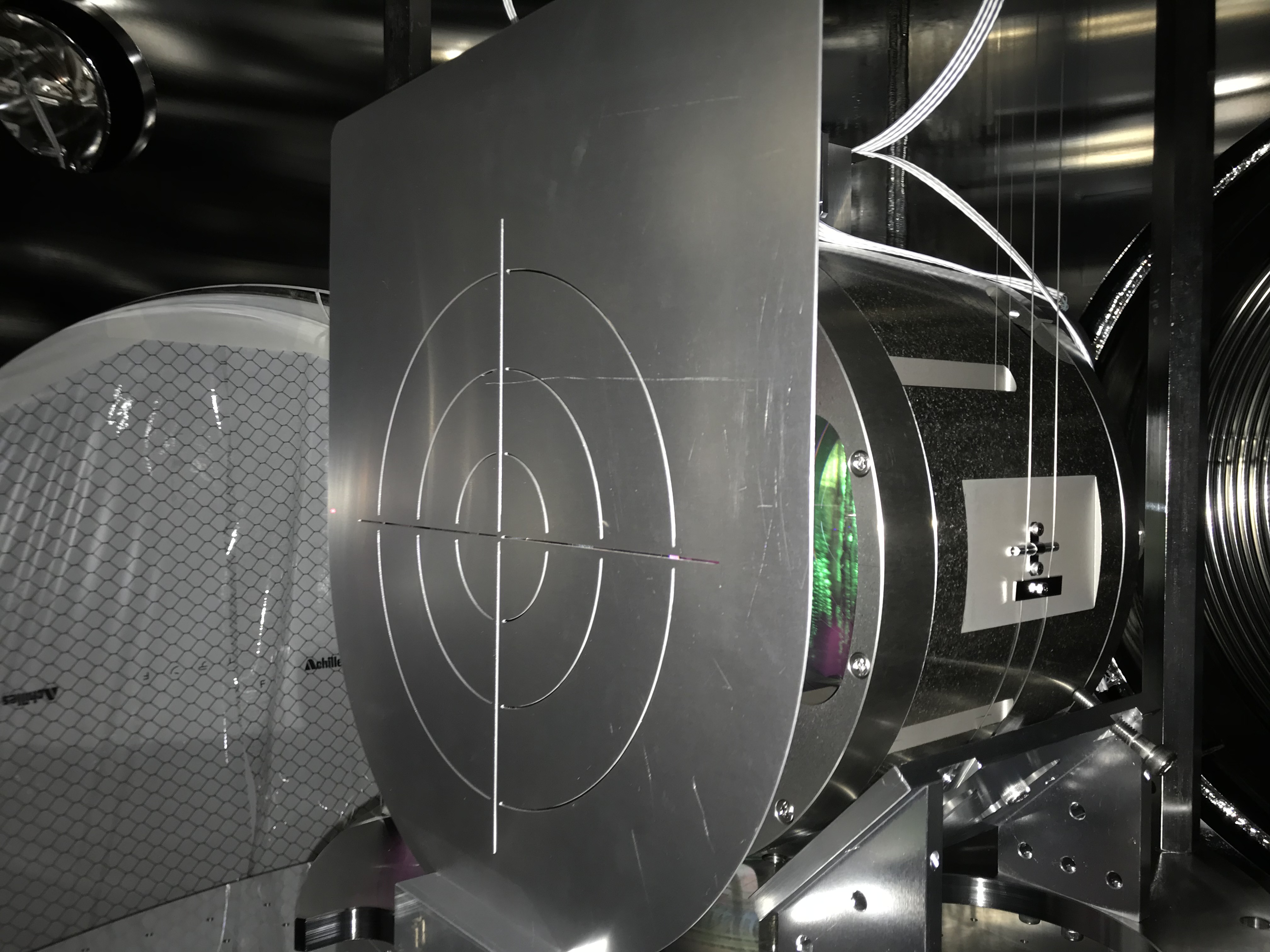
-- We aligned IMMT2 (by pushers for YAW, and by manually rotating the pico screw with hands for PIT) so that the beam hits the center of PR2, using a brand-new beam target in front of PR2 mirror.
-- We did not move PR2 but found the reflecton beam from PR2 really close to the center of PR3. That's nice.
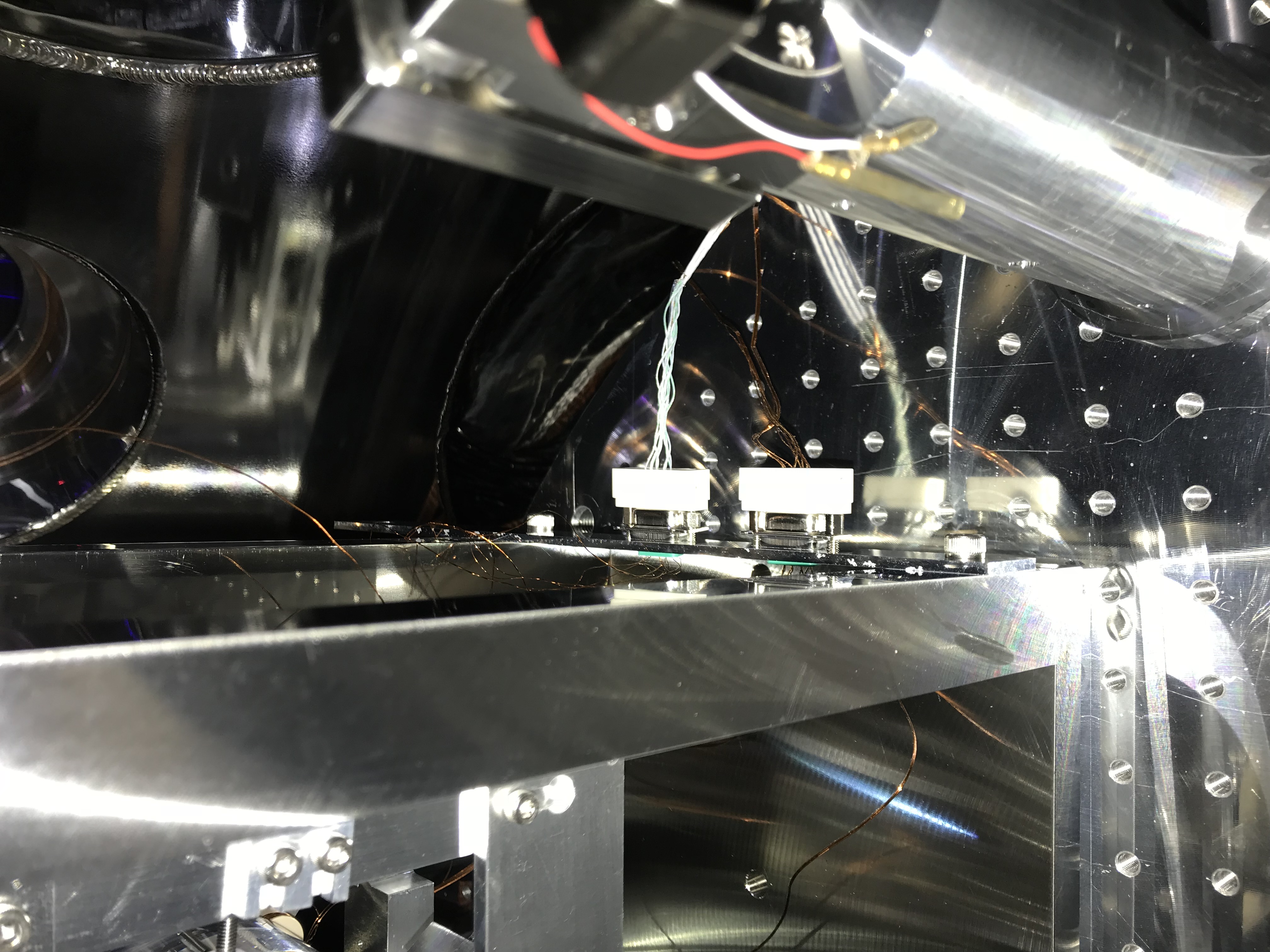
-- We centered oplev QPD for IMMT2, and IMMT1T QPD

Issue:
-- IMMT2 pico is not functionalangry
-- We could not center the oplev QPD for IMMT1 without the QPD clipping the IMMT1 transmissoin beam.

Comments to this report:
tomotada.akutsu - 23:28 Monday 03 September 2018 (5992) Print this report

> We could not center the oplev QPD for IMMT1 without the QPD clipping the IMMT1 transmissoin beam.

Shall we try folded type oplev?? But I'm not sure whether we have required parts now or not.

yutaro.enomoto - 0:07 Tuesday 04 September 2018 (5993) Print this report

> Akutsu-san
It would be great, but we think a folding mirror outside the chamber will be good enough. Let us discuss about this tomorrow.

yutaro.enomoto - 0:23 Tuesday 04 September 2018 (5994) Print this report

= Movement of IMMT1 suspension frame =
The 1st picture shows the position before the work, while the 2nd shows the position after the work.
This move was done based on 2377.

= The beam target =
See the 3rd picture. Coolcool

= IMMT2 pico =
We tried:
- to move pico with a "joy stick"
- to use another pico driver instead
and we checked the cabling inside/outside the chamber by eyes, but falied.
We don't really know what is wrong.

= IMMT2 position =
Just for reference; the 4th picture shows the position before the work, while the 5th and 6th pictures show the postion after the work 

Images attached to this comment
keiko.kokeyama - 10:13 Tuesday 04 September 2018 (5996) Print this report
forgot to mention on klog. One of the two motors of STM1 and STM2's pico didn't work.

POM pico hasn't been tested since iKAGRA (?) I remember it didn't properly work either.
tomotada.akutsu - 16:15 Tuesday 04 September 2018 (6002) Print this report

By the way, see here for the arrangement of the light beams back of IMMT1. I don't have clear memory about who did the arrangement of the optical table on the pylon outside of the IMM chamber; U-Toyama people or Kokeyama-san?

keiko.kokeyama - 18:38 Tuesday 04 September 2018 (6005) Print this report
Akutsu-san,

The breadboard was designed, purchased and installed by University of Toyama. IMMT1 oplev installation was done by me and Niigata university, and re-installed by Akutsu-san, Simon and me (klog 3347). Oplev calibration was done by Niigata University (Chen-kun et al). Now it's re-done by Enomoto-kun.
tomotada.akutsu - 13:30 Wednesday 05 September 2018 (6009) Print this report

I see, thanks.

yutaro.enomoto - 13:34 Wednesday 05 September 2018 (6010) Print this report

= IMMT2 pico =
Ohishi-san reported that flipper cable for IMMT2 pico seems to be not working, as well as those for STM1/2 picos.
We will fix them soon.

Search Help
×

Warning

×