Reports 1-1 of 1 Clear search Modify search
IOO (Laser Bench)
yutaro.enomoto - 20:51 Thursday 21 June 2018 (5346) Print this report
VCO noise measurement@UToyama; having a trouble in VCO

[Sugimoto, Enomoto]

We started the phase noise measurement of VCO made by G&H.
But we could not stably operate this VCO; even if we changed the FM voltage applied to the VCO, the frequency of the output did not go beyond ~55 MHz.
At this point (~ 55 MHz), we could not even increase the FM voltage. (If we increase the request voltage of a function generator, the output measured by oscilloscope would not increase.)
We once managed to fix (?) this issue by changing the connector to the FM port, but this strange behavior happened later again.
We don't really know why this strange behavior happensdevil

Comments to this report:
kiwamu.izumi - 5:19 Friday 22 June 2018 (5349) Print this report

Hey Yutaro,

Thanks for doing this.

I have a question --- how big was the RF power at the output of the G&H driver? Was it at the full power of about 30 dBm or at some itermediate RF power? If, for some reason, the RF power was ridiculously low, some behavior may not make sense.

yutaro.enomoto - 8:16 Friday 22 June 2018 (5350) Print this report

Hi Kiwamu,

Thank you for your comment.
We did not measure the output power directly, but in most cases we tried with ~ 30 % voltage of its max. range applied to AM port, meaning the output should have been ~ 10 dBm.
We tried several different levels of AM including its maximum, but we did not observe any changes.
Anyway, we are going to measure the RF output level and try something like keeping the VCO outputing 30 dBm for a while to "warm" the circuit, to see if any changes of behavior happen.

yutaro.enomoto - 8:27 Friday 22 June 2018 (5351) Print this report

= Voltage to Frequency efficiency measurement of VCO =

Yesterday we measured this while the VCO seemed working properly.
Sugimoto-kun performed a linear fitting of this as shown in the attached figure.
The result is: 6.22(4) MHz/V or f = 6.22 * V + 43.6(3).
We might want to remeaure it after the strange behavior of the VCO is solved, though.

Images attached to this comment
yutaro.enomoto - 20:24 Friday 22 June 2018 (5360) Print this report

Today's work by Sugimoto and Enomoto @UToyama
= VCO strange behavior solved =

After some trial and error, we found that this strange behavior was probably due to reflection of RF signal caused by improper termination:
In the previous setup, the slow output of a Common Mode Servo was splitted by a T-connector, and one side of this went to FM input of the VCO via a few meter long BNC 
and the other side went to Moku:Lab input via a ~5 m long BNC, to monitor the control signal. We tried both 50 ohm termination and Hi-Z termination at Moku:Lab input.
When we disconnected a cable from the T-connector that went to Moku:Lab, the strange behavior we were seeing vanished, which indicates the splitting the output of the Common Mode Servo with a ~ 5m long cable was the cause.

I did not care so much about the termination or impedance-matching related things because I assumed only audio band signal is related to this FM port of VCO and so the termination does not matter.
However, it turned out it DOES!!
 

= PLL of VCO achieved for the phase noise measurement of the VCO =

We made a phase lock loop that controls the frequency of VCO to follow that of a more stable oscillator.
The current setup is the following:
-- take a product VCO output and output of the stable oscillator by a mixer
-- the output of the mixer goes to the input of a Common Mode Servo
-- offset voltage is added to the signal line by using the CMS. The offset voltage is produced by a function generator.
-- the slow output of the CMS is then sent to the FM port of the VCO
All the switchable filters in the CMS is turned off except for a variable gain stage, which means only 100kHz LPF is there.
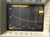
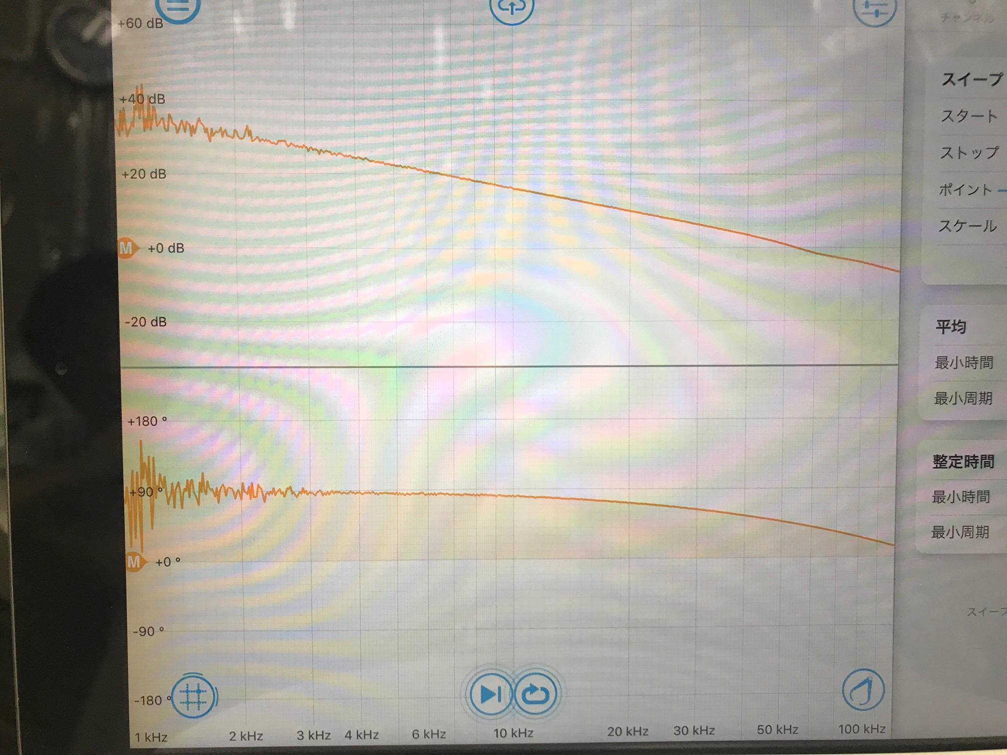
The attached figure shows the open loop transfer function of this PLL.

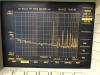
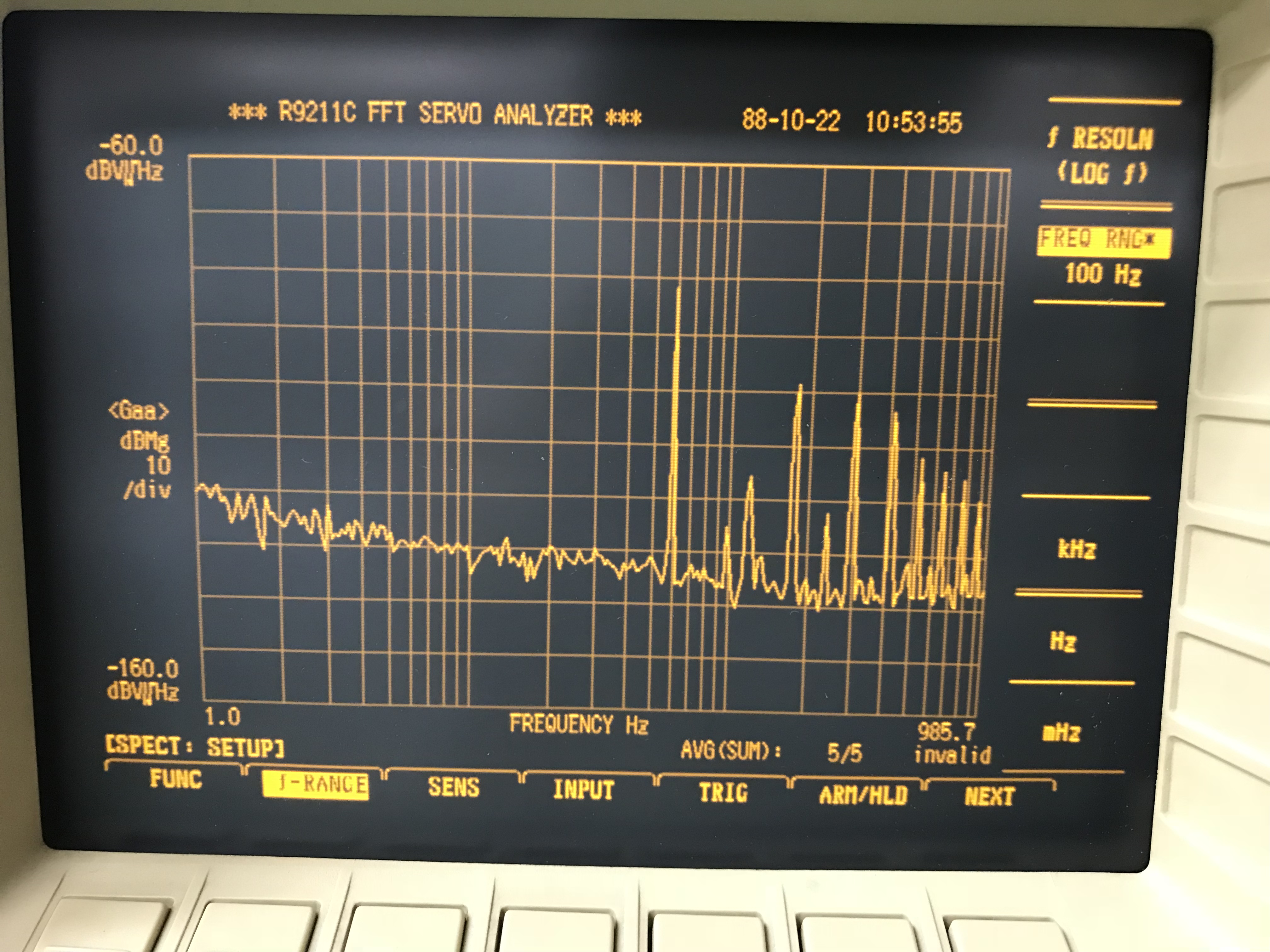
Then we measured the power spectrum of the control signal, but it turned out that it was too noisy for at least two reasons:
1. The offset voltage is not stable enough
=> We quickly made a passive LPF that has two real poles at 0.1 Hz. This filter worked as expected.
2. The output of the CMS was too noisy
The noise level of the output was something like 10-5 V/sqrt(Hz), which seems unusual.
I guess some part of this CMS we have is broken and increases the noise. In fact, some function of the CMS cannot be used.
=> We quickly made a summing filter for adding offset that will take a place of the CMS.
When we were checking the functionality of the summing filter, the time was up for this week.

Next thing to do:
Achieve PLL again with the summing filter and the stabilized offset and then measure the control signal, to evaluate the frequency stablity of the VCO.

Images attached to this comment
yutaro.enomoto - 19:34 Wednesday 27 June 2018 (5406) Print this report

= Quick report: VCO noise measurement finished =
[Sugimoto, Enomoto]

By phase-locking the VCO, we evaluated the frequency noise of the VCO.
The attached pictures show the ASD of the control signal of the PLL.
The actuator efficiency is ~ 6 MHz/V, so adding the offset of 136 dB to the vertical axis will give you the frequency stability.
Therefore, roughly
2 Hz/sqrt(Hz) @10 Hz,
6 Hz/sqrt(Hz) @1 Hz,
60 Hz/sqrt(Hz) @0.1 Hz,
which seems quite high compared to the CARM line width (0.8 Hz).

Detailed report will be posted in a couple of days.

Images attached to this comment
kiwamu.izumi - 8:37 Thursday 28 June 2018 (5411) Print this report

sad

stefan.ballmer - 10:07 Thursday 28 June 2018 (5412) Print this report
yutaro.enomoto - 19:14 Thursday 28 June 2018 (5415) Print this report
Hi Stefan,
Thank you very much for raising some references in aLIGO.
Search Help
×

Warning

×