Reports 1-1 of 1 Clear search Modify search
VIS (SR3)
ryohei.kozu - 18:26 Monday 18 June 2018 (5310) Print this report
SR3 top filter (F0) calibration
[Hirata-san, Koz]
 
We calibrated the SR3 top filter (F0). We hoped the resonant frequency would become ~0.2 Hz when we hung the standard filter. So we tried to find the best compression value which satisfies the above requirement. But we failed.
 
 
Result:
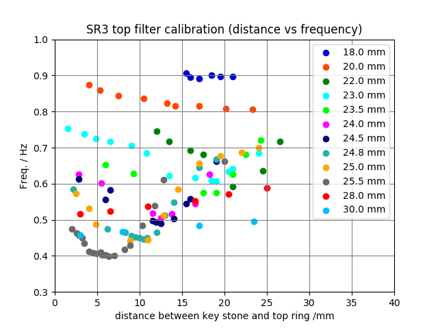
The more we press blades, the lower the frequency is.
On the other hand, the more we press them, the lower the load capacity is.
From today's work, we know that the weight of all components from TM to SF (including the flying saucer and the rod between SF and PI) is 255.4 kg but this value doesn't include the weight of cables. So we estimate the real weight becomes around 256-257 kg.
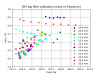
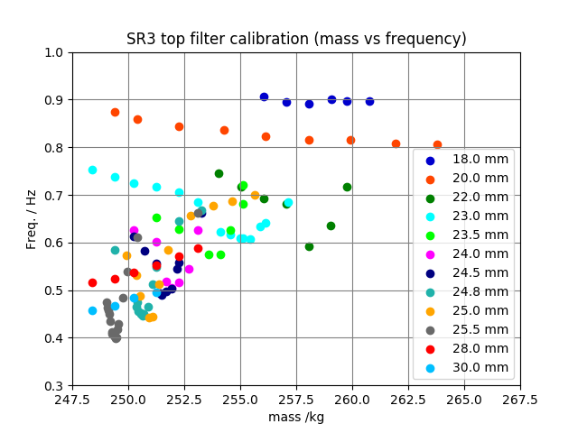
So from this graph, the resonant frequency becomes ~0.6 Hz at best. See picture No.1.
 
 
Solution:
1.
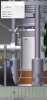
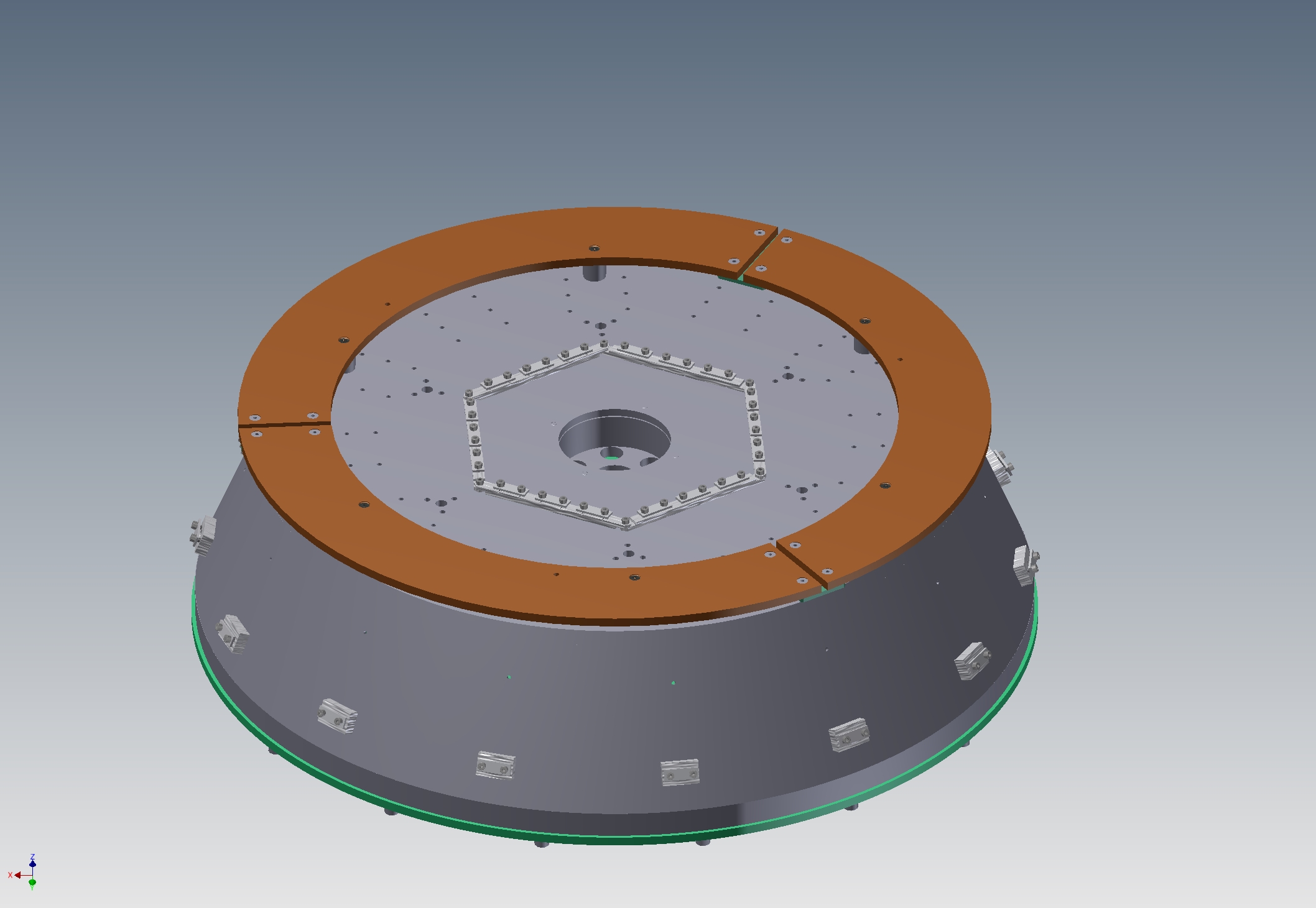
To change the copper boards (on top the SF) to aluminium boards. See picture No.3. This eliminates ~6 kg.
 
2.
To order thinner copper boards. We change the thickness 8 mm to 4 mm and this eliminates ~5 kg.
 
3.
To combine thick aluminium boards and thin copper boards.
For example, if aluminium is 5.5 mm and copper is 2.5 mm, we can eliminate ~4 kg.
 
4.
The final idea is to not install one copper board.
Now we have three boards and they are 10.592 kg in total (without screws) on top.
This idea eliminates ~3.7 kg.
 
Ideas 1, 2 and 3 will take several weeks to install because we would need to order new ones.
We will discuss with Aso-san, Takahashi-san and Mark.
 
 
Data:
I uploaded these data to KAGRA dropbox (home/Subsystems/VIS/TypeB/SR3 calibration/F0 calibration).
Images attached to this report
Comments to this report:
yoshinori.fujii - 6:45 Tuesday 19 June 2018 (5312) Print this report

FYI,
in terms of vibration isolation performance, using F0 with higher resonant frequency would not be a terrible idea according to a quick calculation: the attached shows a simulated mirror displacement with 1% vertical motion coupling with some F0 resonant frequencies (without any controls). Even if the resonant frequency F0 becomes ~1 Hz, we can meet the requirement of SR.

Non-image files attached to this comment
ayaka.shoda - 10:35 Tuesday 19 June 2018 (5313) Print this report

Excellent!! Fujii-kun, thank you very much for the calculation!
Yeah, I think we can compromise the resonant frequency up to 1 Hz.

Actually, it is interesting that vibration isolation rate does not change above 10 Hz.
Is it because the COP effect is set at 60 dB or somewhere, and the vibration isolation rate is satulated already at 10 Hz?

mark.barton - 10:39 Tuesday 19 June 2018 (5314) Print this report

Note: when viewing the frequency vs height plot, keep in mind that the CAD has the nominal position of the keystone at 16.5 mm below the top ring, and we'd really like to work around that range to ensure that the optic is at the right height. If absolutely necessary we could raise or lower the entire PI a few mm on the jacks, but the bellows will be under stress. That suggests an optimum compression of 23 or 23.5 mm, which would give us a load capacity of 255-257 kg and a frequency of 0.6 Hz around 16.5 mm.

Images attached to this comment
Search Help
×

Warning

×